Goal
Produce refrigeration/cooling without mechanical motors or CFC refrigerants by using electricity to electrochemically compress hydrogen.
Problem
High energy consumption and environmental impact of conventional vapor-compression refrigeration systems that rely on mechanical compressors and CFC/GHG refrigerants.
Concept Summary
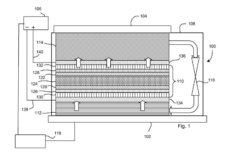
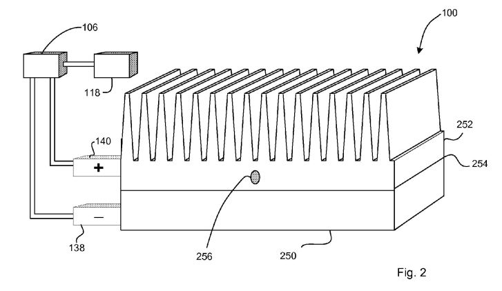
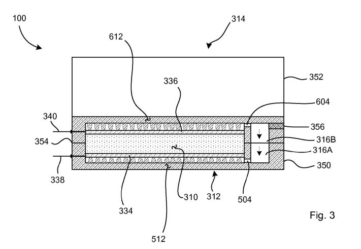
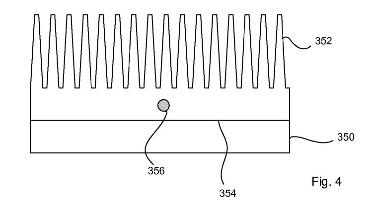
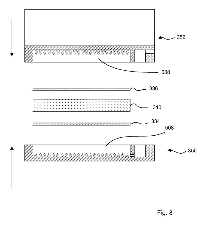
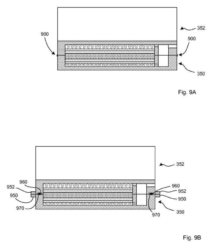
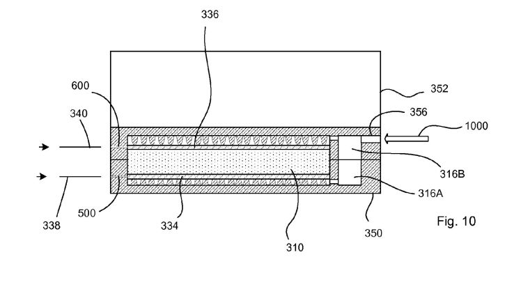
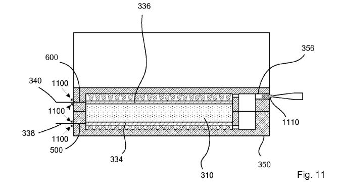
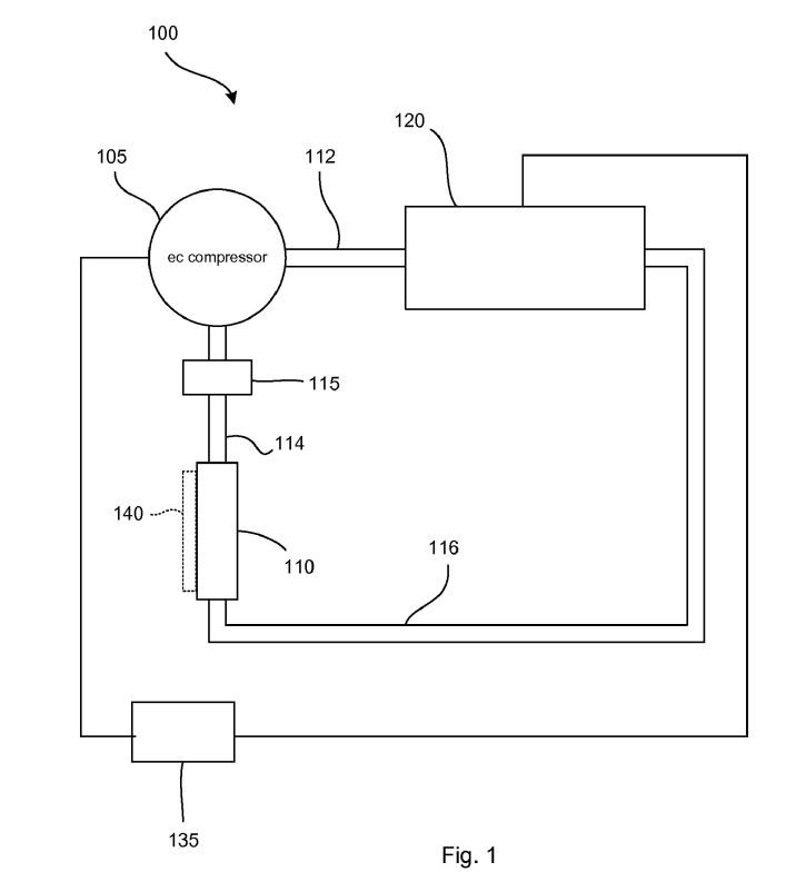
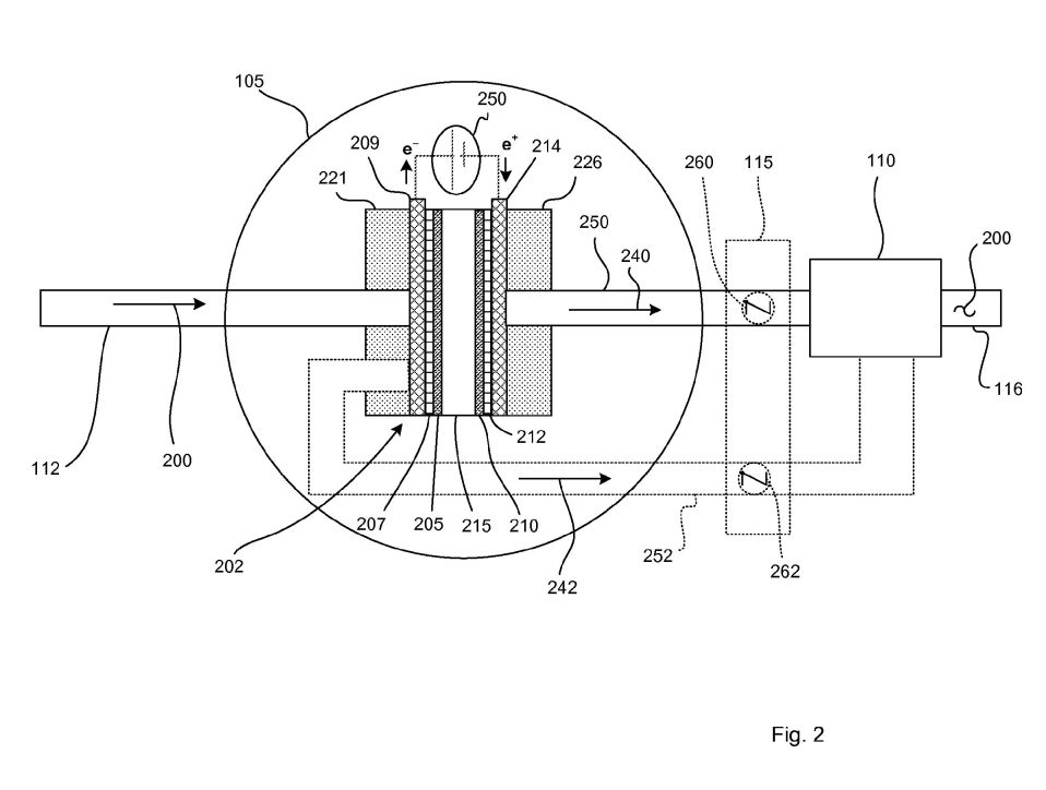
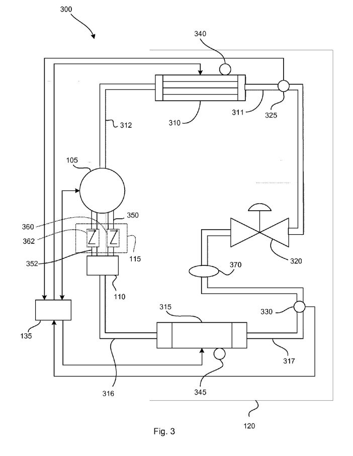
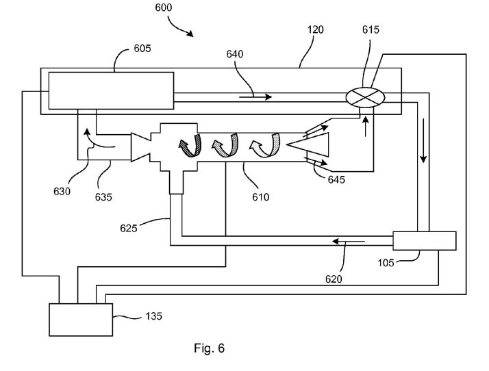
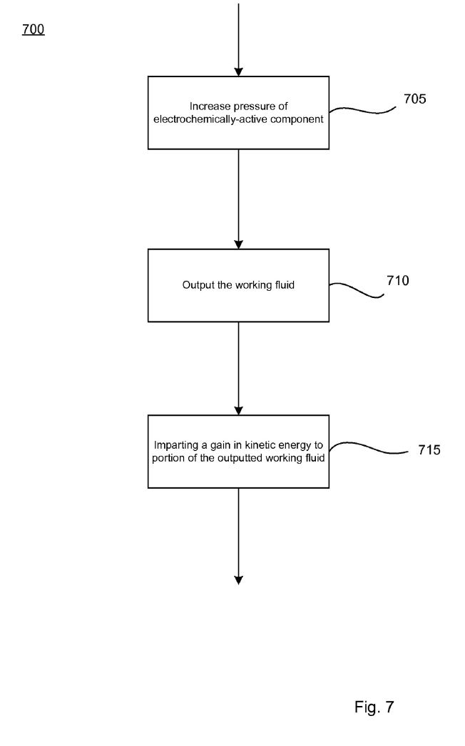
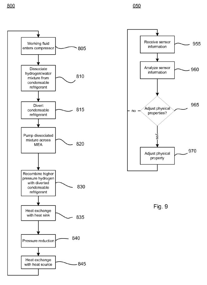
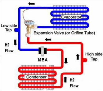
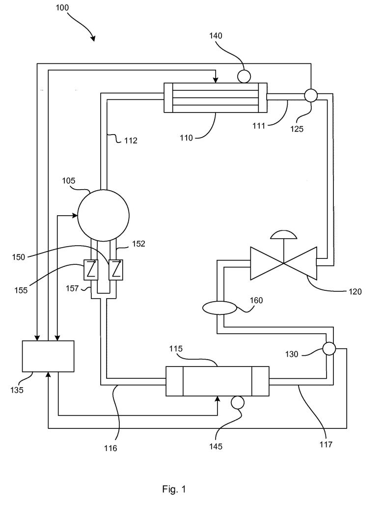
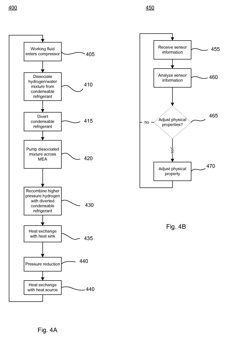
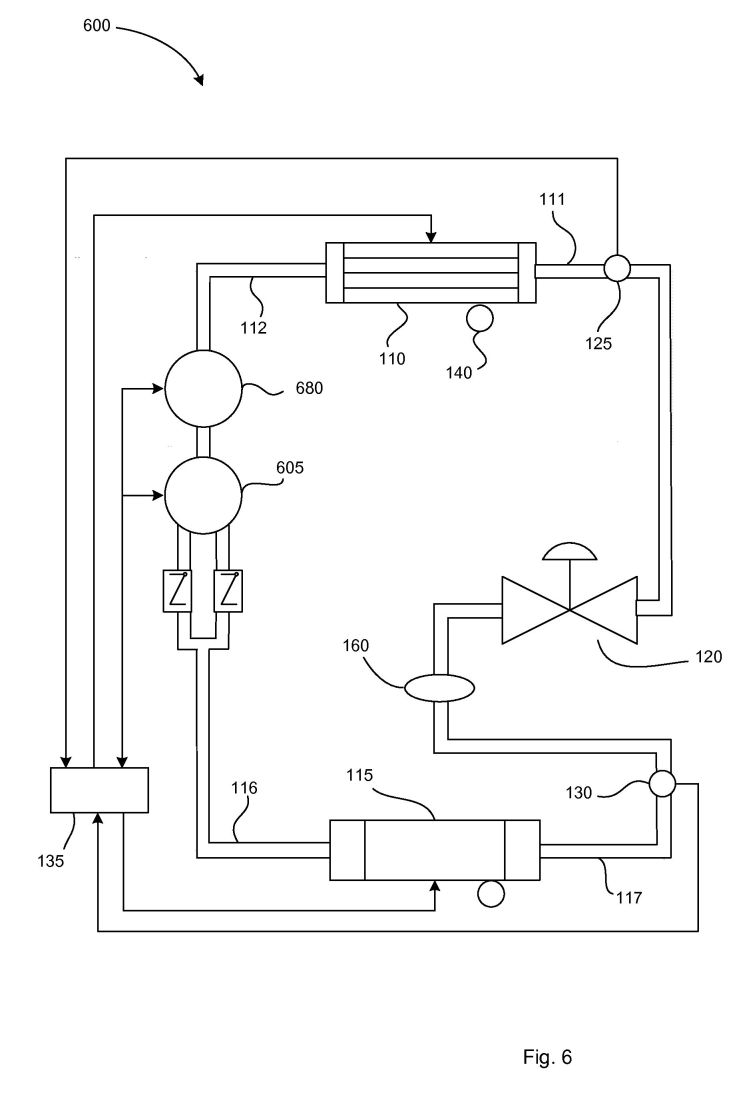
A self-contained heat-transfer system uses a proton-exchange-membrane (PEM) electrochemical cell to compress hydrogen gas, which then pressurizes a mixed refrigerant fluid. The pressurized mixture condenses, expands through a micro-orifice, and evaporates, providing cooling without a motor-driven compressor.
Detailed Description
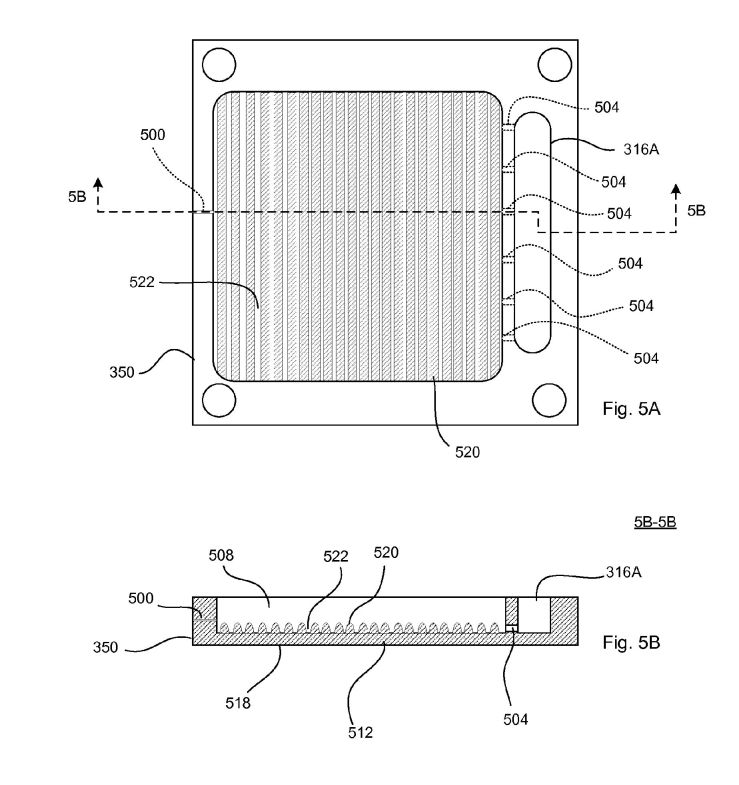
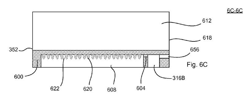
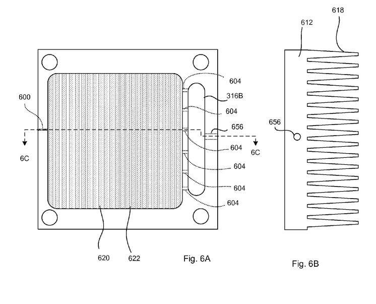
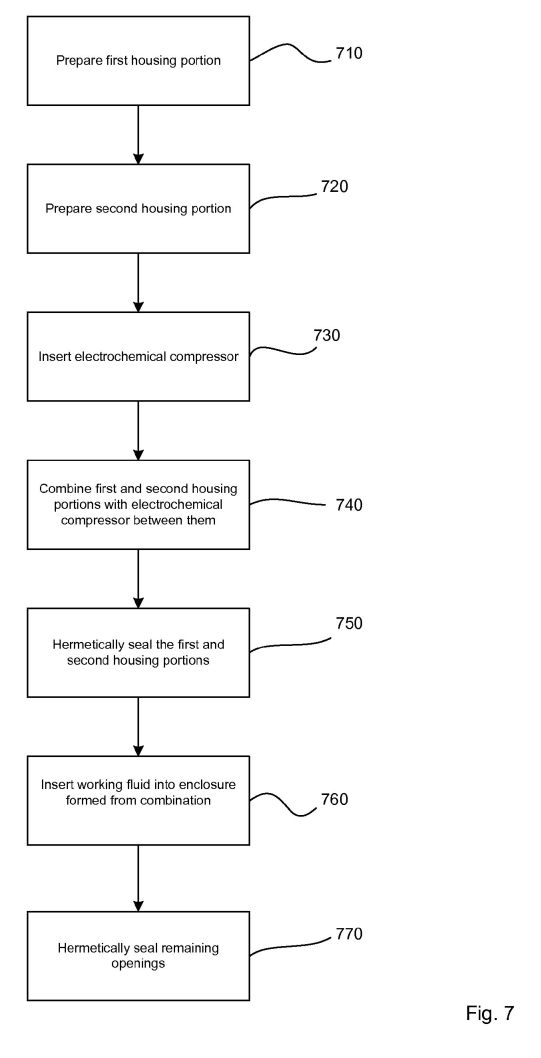
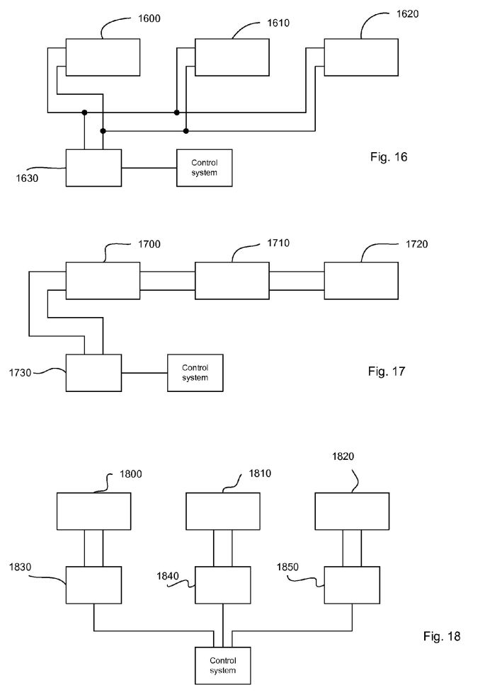
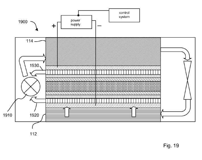
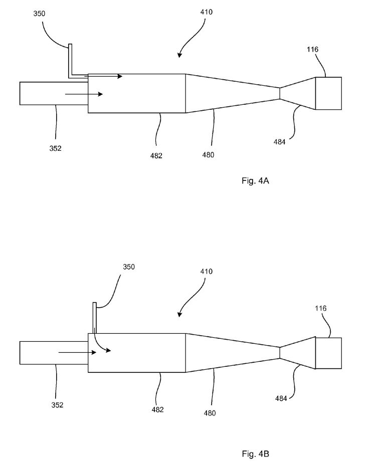
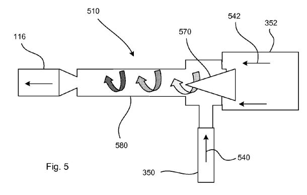
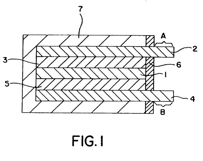
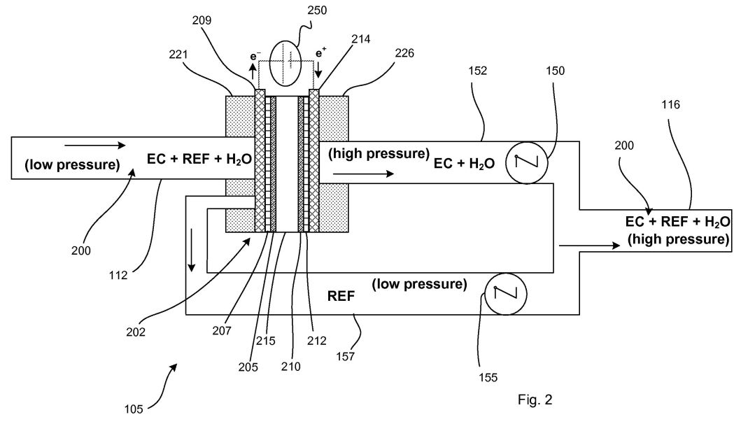
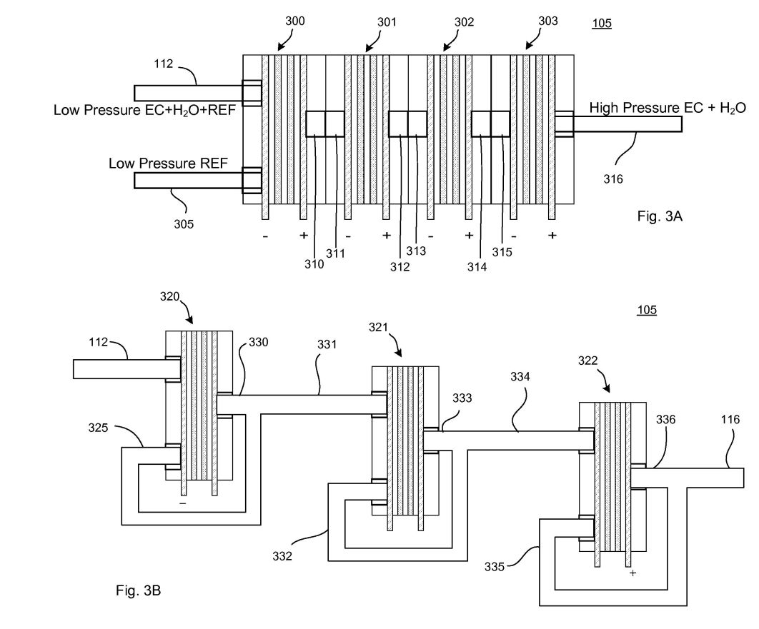
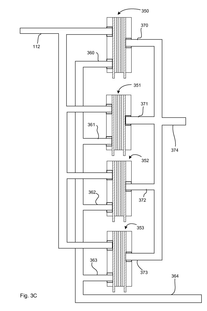
The core component is a PFSA (perfluorosulfonic acid) PEM that acts as a compressor in a closed-loop refrigeration cycle. Hydrogen gas generated by electrolysis is pressurized across the membrane electrode assembly (MEA) to several PSI above atmospheric pressure. The high-pressure hydrogen mixes with a vapor refrigerant, which is then condensed, expanded through an orifice, and evaporated to absorb heat from the object being cooled. The cycle repeats with the EC cell re-pressurizing the mixture. The system is modular, can be sized from 50 W to 5 kW, and requires only electricity as an energy source, eliminating the need for motors, rare-earth metals, and CFCs.
Principles
- Electrochemical compression via proton-exchange membrane
- Thermodynamic cycle of vapor compression
- Hydrogen gas pressure generation
- Heat exchange and phase change
Scientific Domains
Materials
- PFSA (perfluorosulfonic acid) membrane
- Proton-exchange-membrane (PEM) assembly
- Electrode materials (gas-pervious anode and cathode)
- Hydrogen gas
- Refrigerant fluid (e.g., ammonia, R-134a)
- Metal housing and heat-exchanger surfaces
Mechanisms of Action
- Electrolytic splitting of water to generate hydrogen
- Hydrogen permeation and pressure increase across PEM
- Pressurized hydrogen drives refrigerant condensation
- Expansion through micro-orifice provides cooling
Energy Sources
Applications
- Household refrigerators
- Air-conditioning units
- Automotive air-conditioning
- Heat pumps for electronics
- Modular cooling systems
Claimed Performance
2-3x higher efficiency than conventional mechanical compressors; motor-less, low-noise, modular; sizes 50 W-5 kW; no CFCs or rare-earth metals required.
Experimental Evidence
The article references prototype patents, a GE Ecomagination award, and statements that the technology leverages existing fuel-cell PEM technology, but provides no quantitative test data.
Limitations
- Reliance on electricity supply
- Membrane durability and pressure limits (only a few PSI)
- No published quantitative efficiency data
- Scale-up and cost unknown
Red Flags
- Lack of peer-reviewed experimental data
- Marketing language dominates technical description
- No independent replication or third-party testing reported