Goal
Increase fuel efficiency and mileage of internal-combustion engines by vaporizing gasoline before combustion.
Problem
Low fuel economy and inefficient combustion in gasoline engines.
Concept Summary
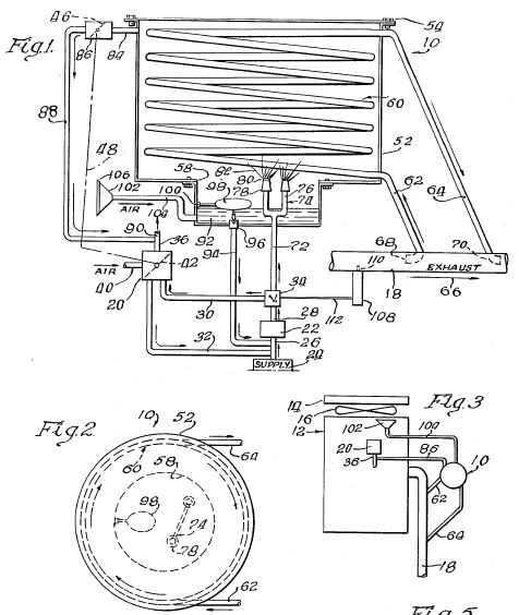
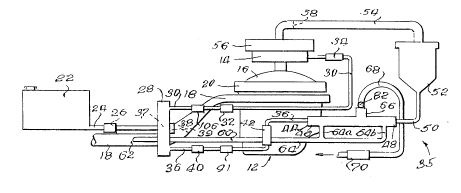
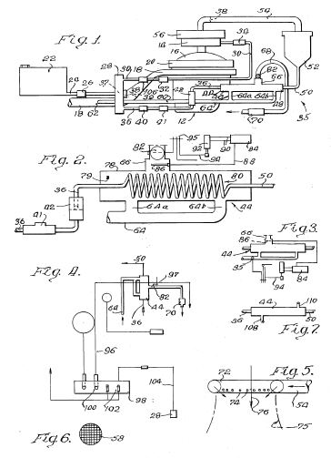
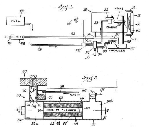
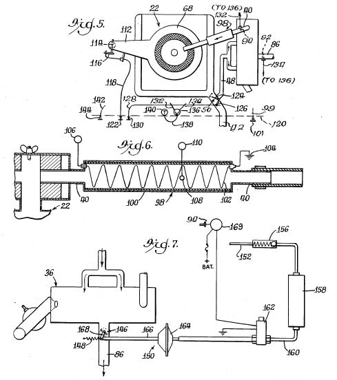
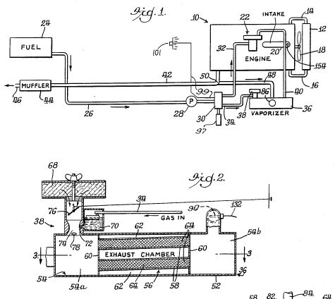
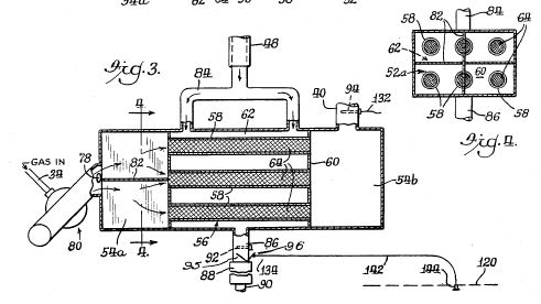
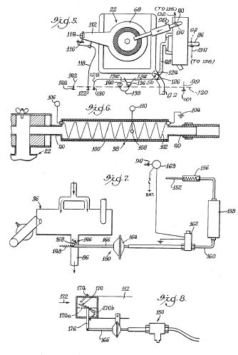
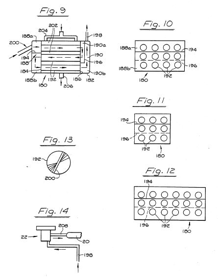
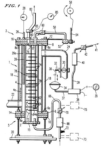
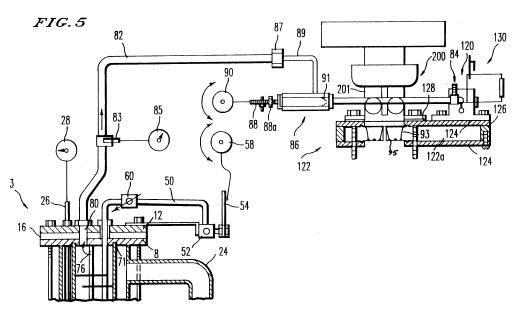
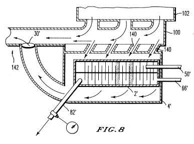
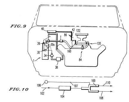
A vaporizer unit is placed in series with a conventional carburetor. Exhaust gases pass through a transverse passage that transfers heat to fuel-carrying tubes lined with wire-mesh. A catalytic converter upstream amplifies the heat. An electric crystal (piezoelectric) cracks heavy fuel fractions. Temperature sensors and solenoid-controlled valves regulate exhaust flow and fuel vapor temperature (~=250-260 deg F). Optional electric heater can be added for cold conditions. The vaporized fuel is then fed to the main carburetor, improving combustion efficiency.
Detailed Description
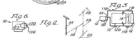
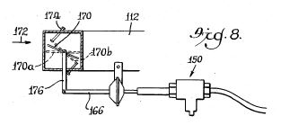
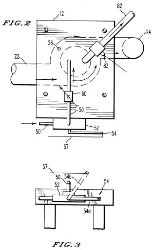
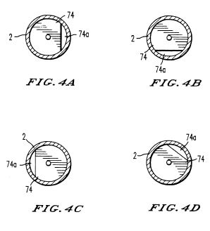
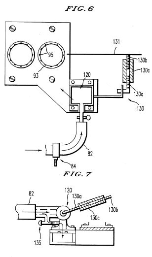
The invention consists of an outer casing containing a fuel passage made of multiple tubes (typically six) with coiled wire-mesh screens. An auxiliary carburetor atomizes fuel and mixes it with air before it enters the tubes. A branch exhaust pipe directs hot exhaust gases through a transverse passage adjacent to the tubes, heating the fuel by conduction and convection. A catalytic converter placed between the exhaust manifold and the heat exchanger raises the exhaust temperature, acting as a heat amplifier. Temperature sensors in the exhaust and vapor outlet lines feed signals to a solenoid-controlled two-way valve that directs fuel either to the main carburetor or to the vaporizer unit. An electric crystal operating at ~1 MHz (powered by the vehicle's 12 V battery) further breaks down heavy fuel molecules. A temperature-controlled flapper valve modulates exhaust flow to maintain vapor temperature between 250 deg F and 260 deg F. An optional electric heater (resistance element) can be installed in the vapor outlet line for cold climates. Manual and automatic controls allow the driver to monitor and adjust vapor temperature and air flow via dashboard gauges and knobs.
Principles
- Heat exchange between exhaust gases and fuel
- Catalytic heat amplification
- Fuel vaporization
- Piezoelectric cracking of heavy fuel fractions
- Temperature feedback control
Scientific Domains
Materials
- steel
- copper
- brass
- wire mesh (screen)
- catalytic converter (ceramic)
- piezoelectric crystal
- resistance heating element
Mechanisms of Action
- Exhaust heat transferred to fuel tubes
- Catalytic converter raises exhaust temperature
- Wire-mesh increases surface area for fuel heating
- Electric crystal vibrates to break down heavy molecules
- Solenoid valve directs fuel based on temperature sensors
Energy Sources
Applications
- Automobile fuel-efficiency improvement
- After-market carburetor retrofit
Claimed Performance
Typical mileage of 65 MPG on a Chrysler V-8, with occasional peaks of 100 MPG.
Experimental Evidence
Ray Covey reported achieving 65 MPG (and occasional 100 MPG) after installing the vaporizer on his Chrysler V-8. Several customers had units installed and experienced higher mileage.
Replication Status
Installed for several customers; no independent third-party testing reported.
Limitations
- Performance depends on sufficient exhaust heat; may need auxiliary heater in cold climates
- Complex plumbing and valve control may be difficult for DIY installation
- No published independent testing or certification
Red Flags
- Performance claims are anecdotal and lack quantitative data
- No peer-reviewed studies or third-party validation
- Potential for mis-use of electric crystal without proper safety measures