Goal
Provide an electrical resistor that exhibits essentially no residual self- or mutual-inductance and negligible reactance at high frequencies.
Problem
Parasitic inductance and reactance of conventional resistors degrade performance in UHF, microwave, and pulse (radar) circuits.
Concept Summary
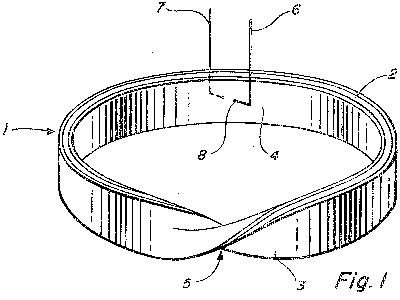
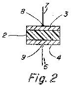
A Moebius-shaped resistor is built from two equal-length conductive ribbons (or bifilar wire) mounted on opposite sides of a dielectric strip, twisted into a single-sided Moebius surface and soldered so that the terminals are directly opposite each other. Currents travel in opposite directions, causing their magnetic fields to cancel and yielding a non-inductive, non-reactive resistor.
Detailed Description
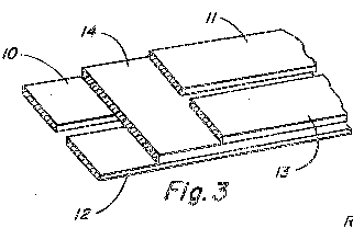
Two ribbon conductors of equal length are affixed to opposite faces of a dielectric strip. The assembly is given a half-twist and the ends are joined to form a Moebius loop. The ribbon ends are soldered together, and the resistor terminals are attached to the opposing solder joints. Current applied to the terminals splits into two equal components that travel in opposite directions; their electromagnetic fields cancel, eliminating inductance. The design can use bifilar wire instead of a dielectric-sandwiched ribbon, or thin-film conductors on a flat surface. Multiple Moebius loops can be placed side-by-side on the same dielectric to create multi-resistor units without affecting each other's time constants. The resistor can be folded or wrapped around various shapes without changing its performance, provided the conductor spacing remains unchanged.
Principles
- Magnetic field cancellation
- Topological single-sided surface (Moebius strip)
- Bifilar winding
- Opposite current directions
Scientific Domains
Materials
- Conductive ribbon (e.g., aluminum tape)
- Dielectric substrate (masking tape, non-conductive plastic)
- Bifilar wire
- Metal foil
Mechanisms of Action
- Opposite currents produce equal and opposite magnetic fields, cancelling inductance
- Single-sided Moebius geometry prevents mutual coupling
- Balanced pulse propagation yields low time constant
Applications
- Radar pulse circuits
- UHF and microwave signal paths
- Miniaturized high-frequency boards
- High-speed digital pulse lines
Claimed Performance
Measured residual reactance 0.003 uH, resistance 0.022 Omega, very low time constant for a small resistor.
Experimental Evidence
The first experimental Moebius resistor was built from aluminum tape conductors on masking-tape dielectric; it exhibited 0.022 Omega resistance and 0.003 uH residual reactance.
Limitations
- Terminals must be directly opposite; otherwise inductance appears
- Conductors must not touch; spacing must be maintained
- Performance may degrade at frequencies beyond a few GHz
- Manufacturing tolerances for the twist and solder joints