← Back to category

Parallel Path Magnetic Amplifier

Inventor: Charles (Joe) Flynn
Device: Parallel Path Magnetic Amplifier
Folder: flynn
Original: Open article
Confidence
0.60
Practicability
0.50
Evidence
0.40
Fringe Score
0.80
Risk
0.20
TRL
5

Goal

Provide higher-power-density, lighter, cooler, and more energy-efficient magnetic actuators, motors and generators by steering permanent-magnet flux with low-power coils.

Problem

Conventional electromagnetic devices are relatively heavy, bulky, generate excess heat, and have limited efficiency.

Concept Summary

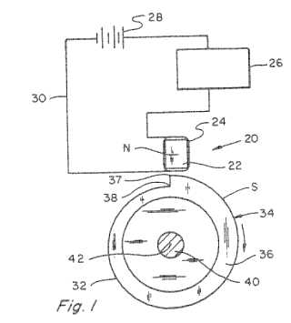
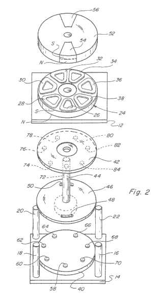
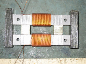
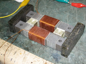
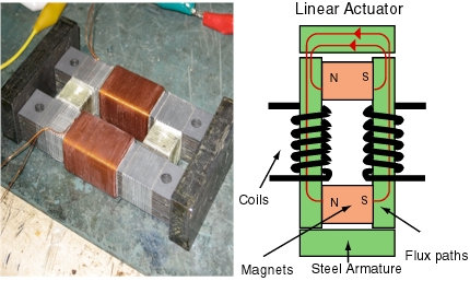
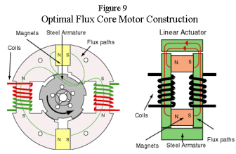
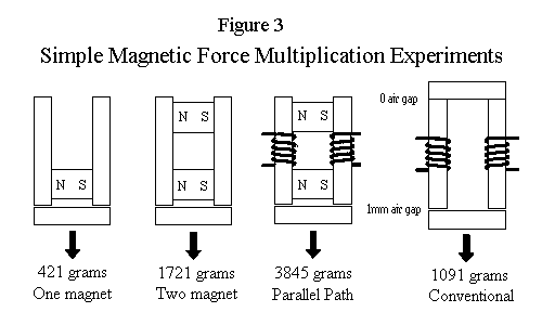
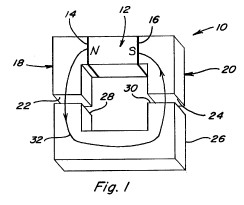
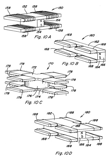
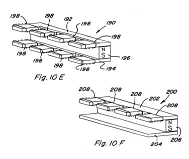
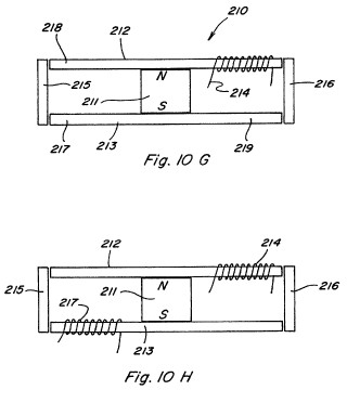
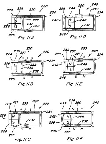
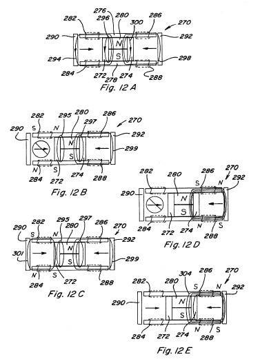
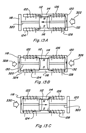
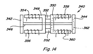
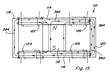
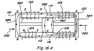
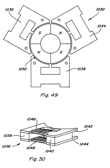
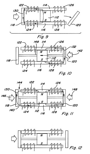
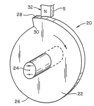
Parallel Path Magnetic Technology (PPMT) uses two or more permanent magnets placed in parallel with flux-steering coils between them. By pulsing the coils, the magnetic flux is redirected, producing a multiplied force or torque that can be held without continuous power. The principle claims leverage ratios greater than 1:1, enabling efficiencies reported above 100 % and power densities higher than conventional designs.

Principles

  • Magnetic flux steering with parallel circuits
  • Leverage of permanent-magnet flux
  • Transient coil pulses to switch magnetic polarity
  • Retention of force/torque after coil power is removed

Scientific Domains

Physics Electrical Engineering

Materials

  • NdFeB (N-35) permanent magnet
  • Copper (field coil, copper pipe for experiment)

Mechanisms of Action

  • Flux steering coils produce a magnetic polarity that couples with permanent-magnet flux
  • Combined flux yields a squared-force law, multiplying output force
  • Air-gap creation locks the actuator in a high-force state without power

Energy Sources

Electrical energy (coil current) Intrinsic magnetic field of permanent magnets

Applications

  • Industrial motors
  • Aerospace actuators
  • Automotive powertrain
  • Marine propulsion
  • Energy generation

Claimed Performance

Efficiencies above 100 % (over-unity) reported; torque up to 2.5 x line current; prototypes ranging from 5 W to 10 kW.

Experimental Evidence

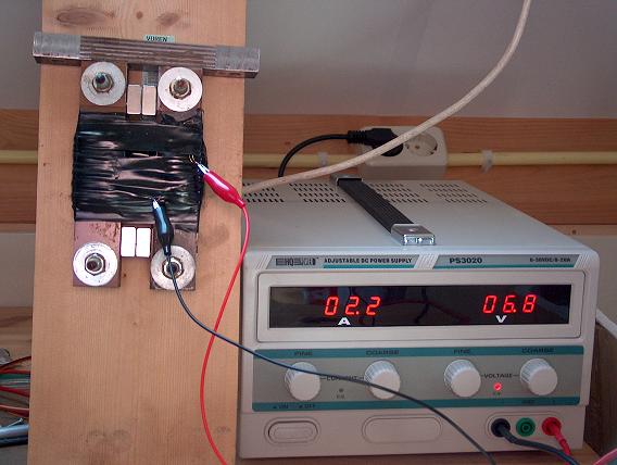
Flynn Research has built >50 prototypes and production models; a floating-magnet demonstration shows magnetic steering in a copper pipe; claimed efficiencies above 100 % are described as experimentally determined.

Limitations

  • No independent, peer-reviewed verification of over-unity claims
  • Reliance on proprietary patents and limited public data
  • Scalability and long-term reliability not demonstrated

Red Flags

  • Over-unity efficiency claims
  • References to ether/aether and non-mainstream physics
  • Lack of peer-reviewed experimental data
  • Potential pseudoscientific language
Keywords

magnetic flux steering parallel magnetic circuits over-unity permanent magnet actuator high-efficiency motor

Related Technologies

Magnetic latching actuator Magnetic clutch Magnetic generator

📷 Images

0logo.gif
0logo.gif
10kw_motor_.gif
10kw_motor_.gif
5254925.jpg
5254925.jpg
5304881.jpg
5304881.jpg
5455474.jpg
5455474.jpg
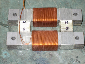
Completed_device_300.jpg
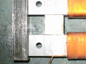
Completed_device_angle_300.jpg
End_laminants_vice_grip_300.jpg
FPPP_photo_and_diagram_hj85.jpg
Fluxmotor.gif
Fluxmotor.gif
Fppm1.jpg
Fppm1.jpg
Fppm2.jpg
Fppm2.jpg
Glue_winding_terminus_300.jpg
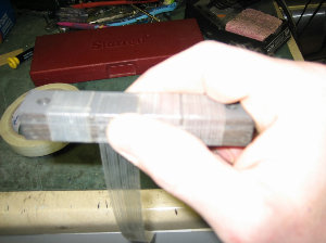
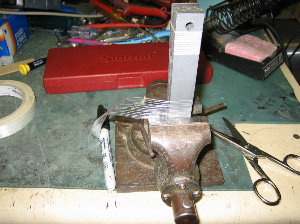
Laminant_bar_stack_in_vice_300.jpg
Laminant_bar_tape_middle_300.jpg
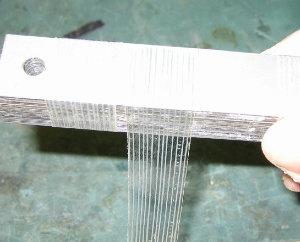
Laminant_bar_tape_middle_b_300.jpg
Laminant_bar_tape_middle_close-up_300.jpg
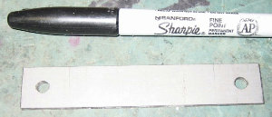
Laminant_one_bar_close-up_300.jpg
Laminant_vice_tape_other_end_300.jpg
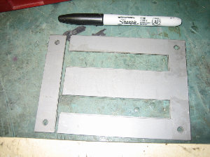
Laminants_300.jpg
Laminants_300.jpg
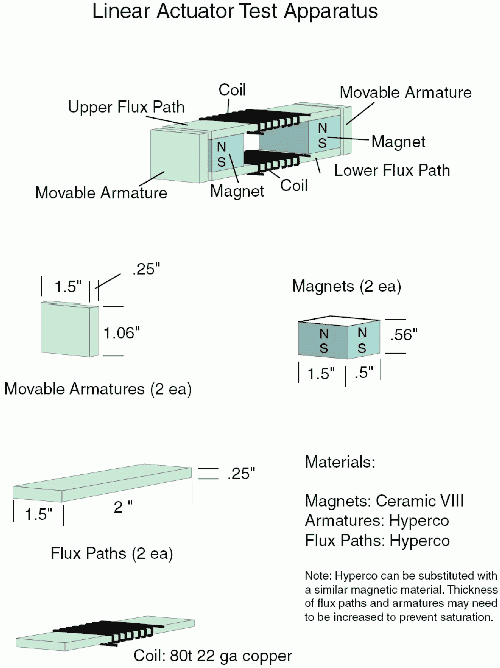
Linear_Actuator_Test_Apparatus_500.gif
Magnets_between_laminant_bars_300.jpg
New_laminant_stack_across_ends_300.jpg
Ppfigure3.gif
Ppfigure3.gif
Two_bars_joined_300.jpg
Wind_bar_begin_300.jpg
Wind_bar_end_b_300.jpg
Wind_bar_first_layer_300.jpg
Winding_close-up_300.jpg
fig1.jpg
fig1.jpg
fig10.jpg
fig10.jpg
fig10ef.jpg
fig10ef.jpg
fig10gh.jpg
fig10gh.jpg
fig11.jpg
fig11.jpg
fig12.jpg
fig12.jpg
fig13.jpg
fig13.jpg
fig14.jpg
fig14.jpg
fig15.jpg
fig15.jpg
fig16a.jpg
fig16a.jpg
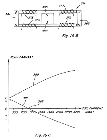
fig16bc.jpg
fig16bc.jpg
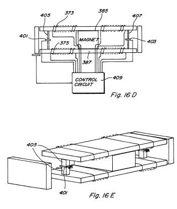
fig16de.jpg
fig16de.jpg
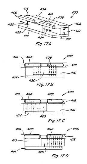
fig17.jpg
fig17.jpg
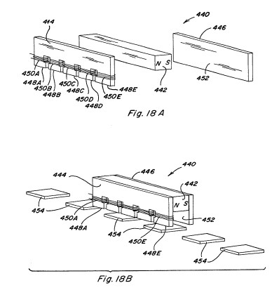
fig18.jpg
fig18.jpg
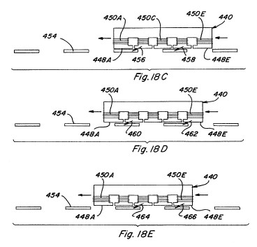
fig18ce.jpg
fig18ce.jpg
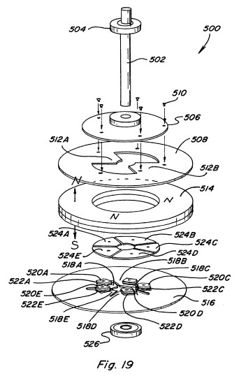
fig19.jpg
fig19.jpg
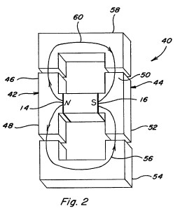
fig2.jpg
fig2.jpg
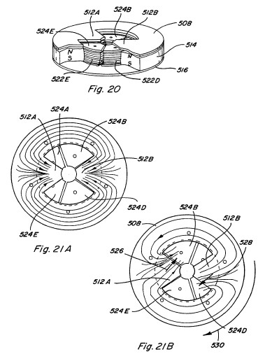
fig20-21.jpg
fig20-21.jpg
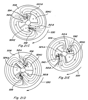
fig21cde.jpg
fig21cde.jpg
fig22.jpg
fig22.jpg
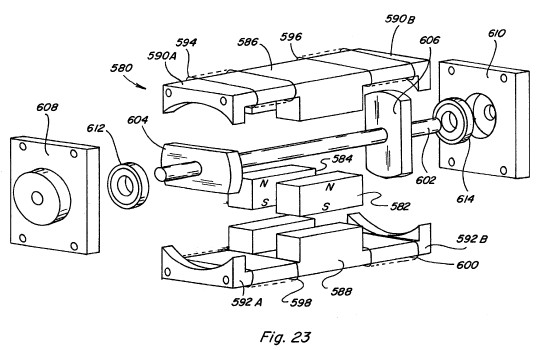
fig23.jpg
fig23.jpg
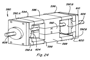
fig24.jpg
fig24.jpg
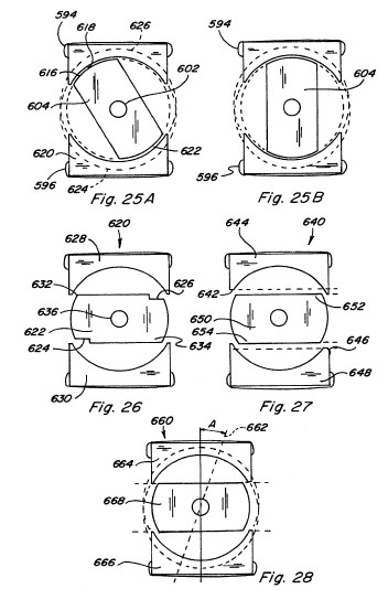
fig25-28.jpg
fig25-28.jpg
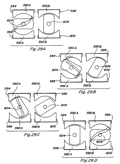
fig29.jpg
fig29.jpg
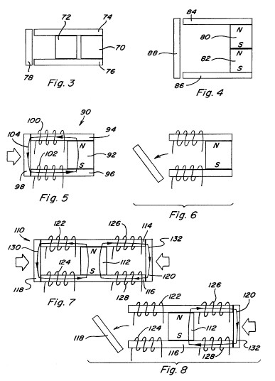
fig3-8.jpg
fig3-8.jpg
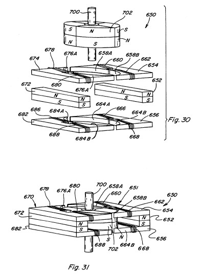
fig30-31.jpg
fig30-31.jpg
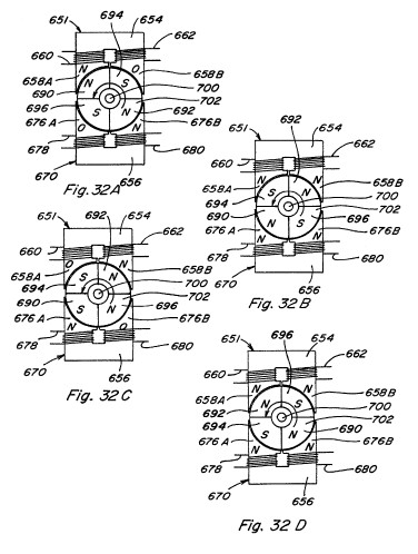
fig32.jpg
fig32.jpg
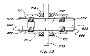
fig33.jpg
fig33.jpg
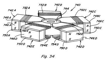
fig34.jpg
fig34.jpg
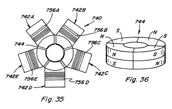
fig35-36.jpg
fig35-36.jpg
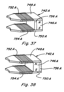
fig37-38.jpg
fig37-38.jpg
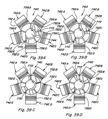
fig39.jpg
fig39.jpg
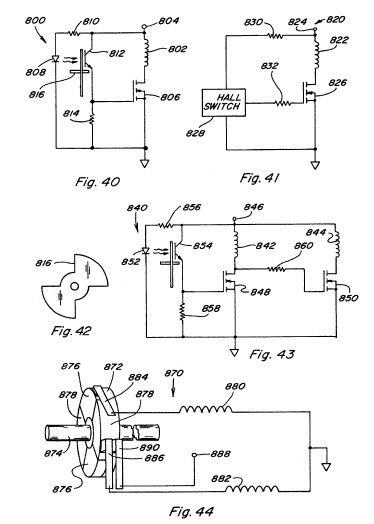
fig40-44.jpg
fig40-44.jpg
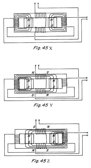
fig45xyz.jpg
fig45xyz.jpg
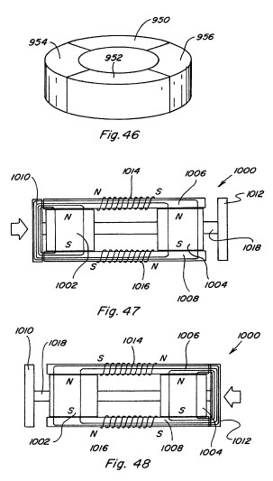
fig46-48.jpg
fig46-48.jpg
fig49-50.jpg
fig49-50.jpg
fig9-12.jpg
fig9-12.jpg