Goal
Rapidly and efficiently remove hazardous pollutants from mining, industrial and agricultural wastewater.
Problem
High chemical consumption and cost in conventional wastewater treatment processes for metal-laden effluents.
Concept Summary
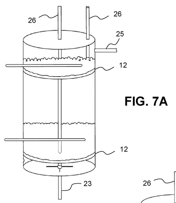
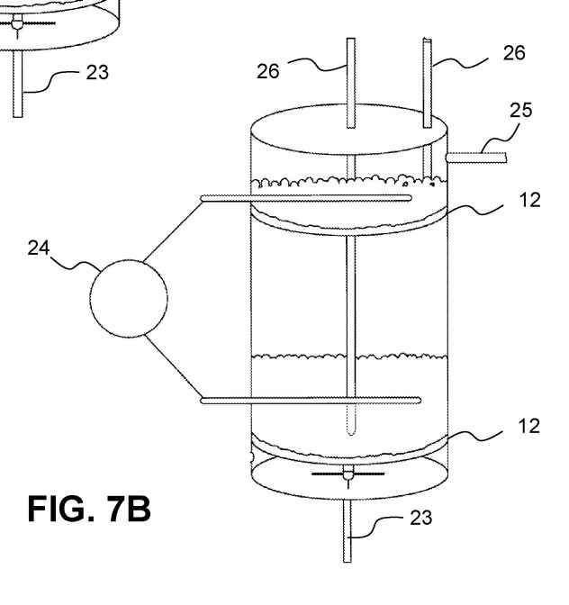
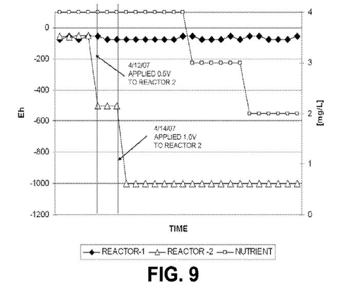
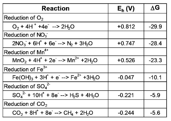
The ElectroBioChemical Reactor (EBR) applies a low-voltage electric potential across two conductive surfaces that support a biofilm of microorganisms. The supplied electrons replace the need for excess nutrients and chemicals, accelerating microbial redox reactions that reduce and precipitate contaminants such as arsenic, selenium, mercury, nitrate and other metals. The system can be powered by a small solar array, making it a low-energy, chemical-light alternative to traditional treatment.
Detailed Description
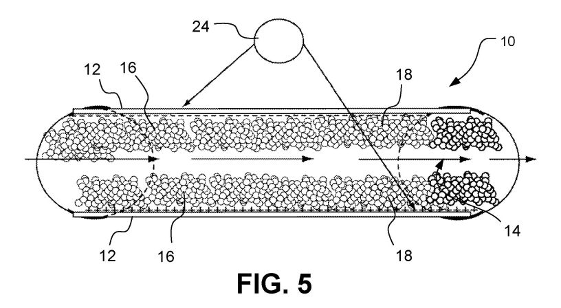
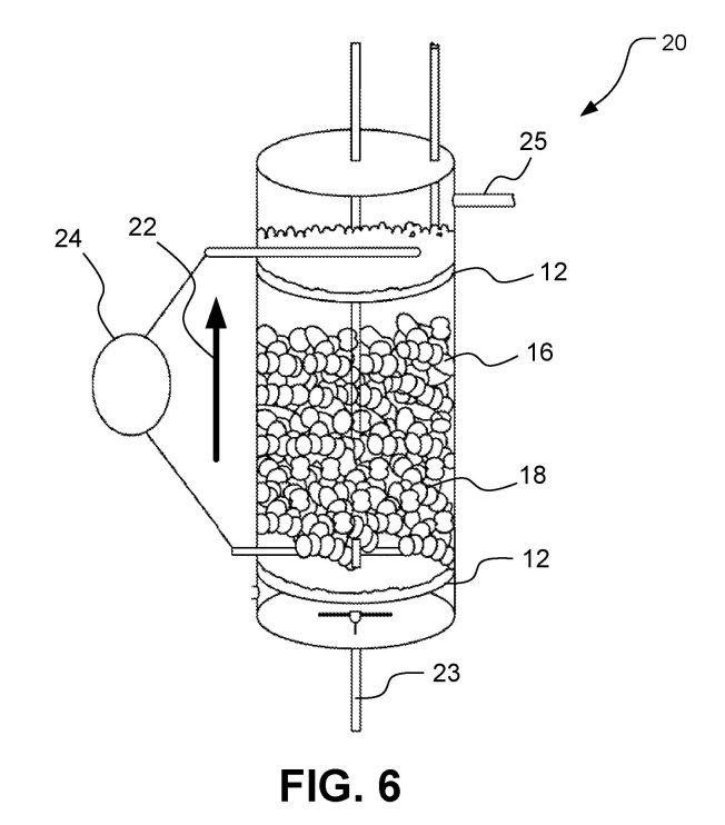
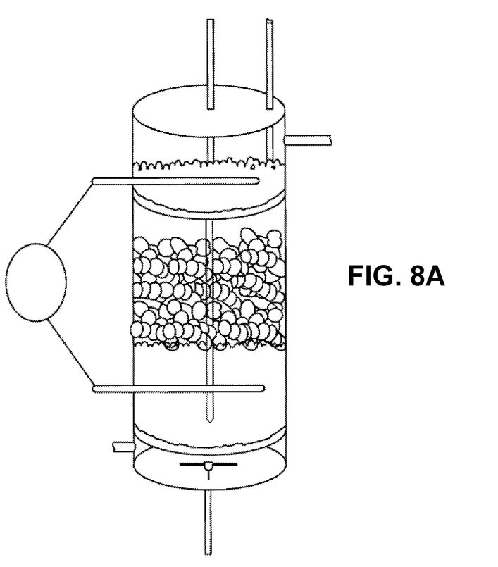
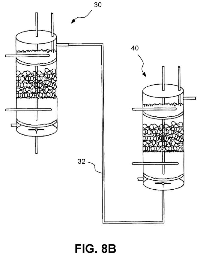
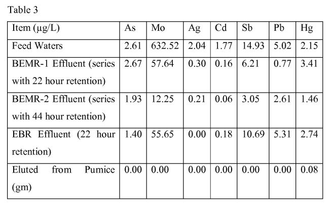
The EBR consists of two parallel active electrodes placed within a flow channel. Microbial cultures (and optionally enzymes) grow on the electrode surfaces. A potential difference (~=1 V) is applied, delivering a massive flux of electrons directly to the microbes. This electron supply enhances the microbes' ability to reduce and bind target compounds, allowing faster removal and lower chemical dosing. Laboratory tests on water from several metal and coal mines demonstrated 2-10x faster contaminant removal compared with untreated bioreactors, while pilot-scale field trials at an inactive gold mine and a planned silver-mine test have shown practical feasibility. The electricity can be sourced from a modest solar power grid, minimizing the overall environmental footprint.
Principles
- Electrochemical stimulation of microbial metabolism
- Redox electron transfer
- Biofilm-based contaminant reduction
- Low-voltage power supply
Scientific Domains
Materials
- Conductive electrode material (e.g., carbon, metal)
- Microbial cultures (biofilm)
- Enzymes or proteins (optional)
Mechanisms of Action
- Application of a low voltage potential across conductive electrodes
- Direct electron donation to microorganisms
- Enhanced microbial reduction and precipitation of metals
- Reduced need for external nutrients/chemicals
Energy Sources
Applications
- Mining wastewater treatment
- Industrial wastewater treatment
- Agricultural runoff treatment
- Metal recovery and recycling
Claimed Performance
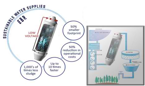
Pollutant removal rates 2-10x faster than conventional bioreactors; chemical usage reduced by >50%; a 1 V source supplies ~10^24 electrons, enabling full-scale operation with a small solar array.
Experimental Evidence
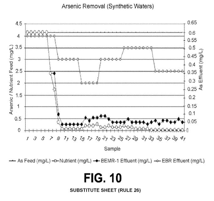
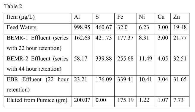
Five laboratory tests on mine water samples (arsenic, selenium, mercury, nitrates) showed accelerated removal; one on-site pilot-scale contract at an inactive gold mine successfully treated arsenic- and nitrate-laden water; a second pilot test at a Yukon silver mine was contracted for spring 2011.
Replication Status
Five laboratory tests completed; one pilot-scale on-site demonstration completed; second pilot-scale test contracted.
Limitations
- Requires reliable electricity (solar or grid)
- Performance depends on maintaining active microbial biofilm
- Scale-up of electrode geometry and flow distribution
- Potential need for periodic biofilm management
Red Flags
- Performance claims (2-10x faster, >50% chemical reduction) lack peer-reviewed quantitative data
- Reliance on pilot-scale results without independent replication
- Potential overstatement of cost savings without detailed life-cycle analysis