Goal
Generate mechanical torque and/or electrical energy with a net energy output greater than the input energy.
Problem
Need for highly efficient energy conversion devices that can produce usable power with minimal external energy input.
Concept Summary
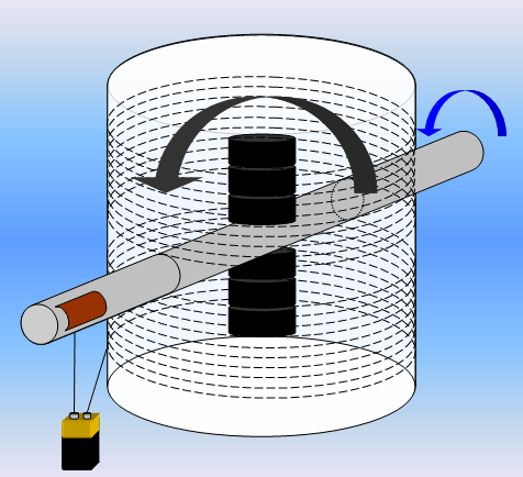
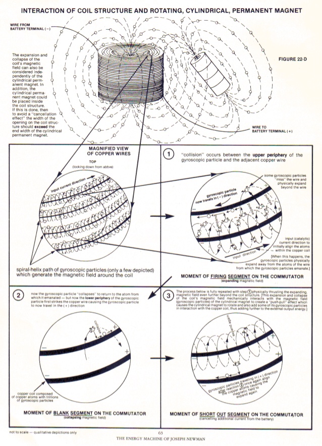
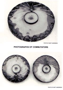
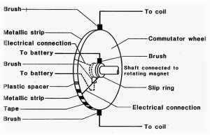
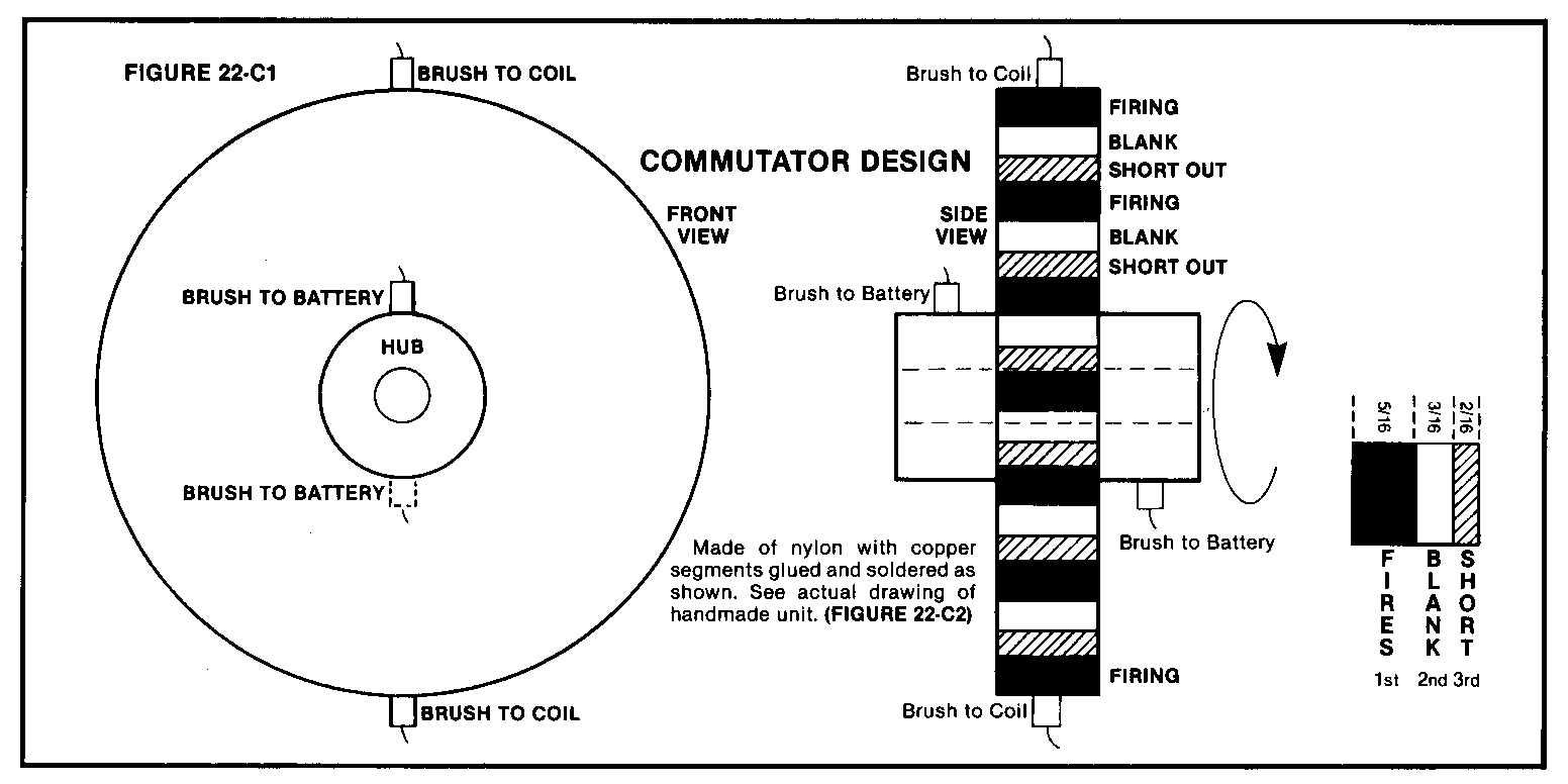
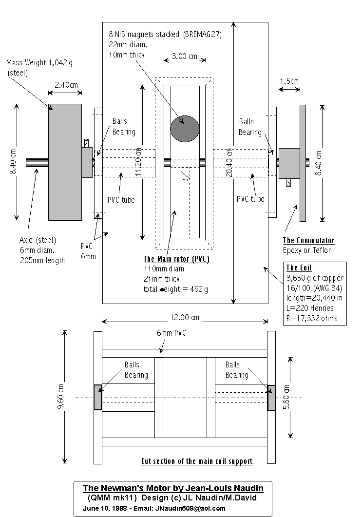
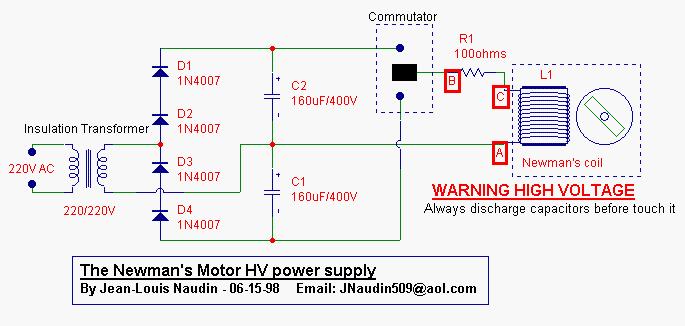
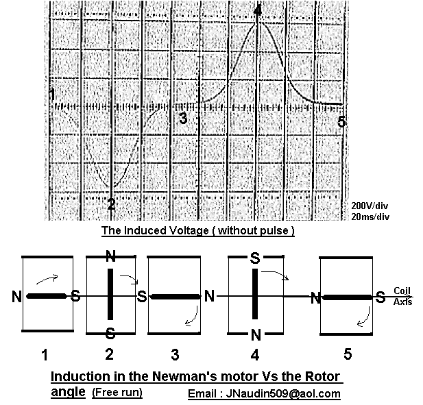
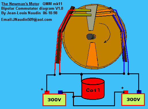
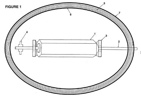
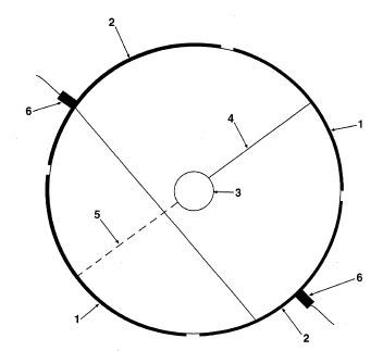
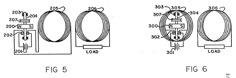
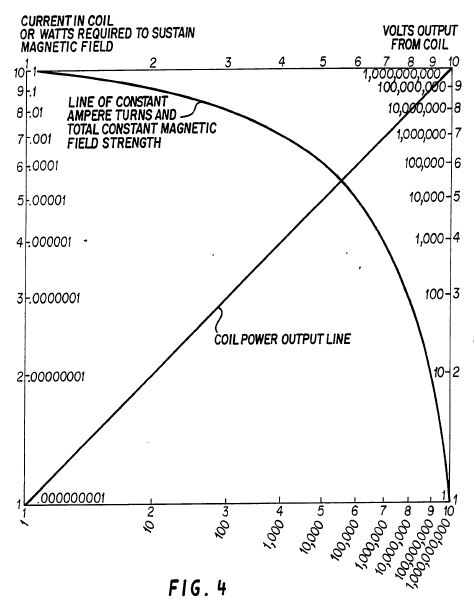
The device consists of a rotating permanent-magnet assembly positioned inside a high-inductance coil. A mechanical commutator (brushes and contacts) switches the coil current at precise angular positions, timing the firing pulse when the rotating magnet is at 90 deg to the coil axis. This timing is claimed to extract magnetic field energy, producing high-efficiency torque in motor mode or strong back-EMF for electricity generation in generator mode.
Principles
- Electromagnetic induction
- Gyroscopic effect of rotating magnets
- Timed commutation (brushes) for optimal pulse timing
- Back-EMF recovery
Scientific Domains
Materials
- Copper wire (AWG 34)
- Neodymium-Iron-Boron (NIB) magnets
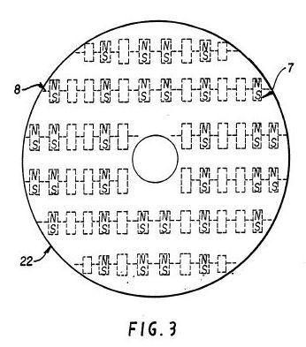
- Bakelite, Epoxy, Teflon, Ertalon (insulating wheel)
- Copper or silver sheet contacts
Mechanisms of Action
- Rotating permanent magnets induce voltage in a coil
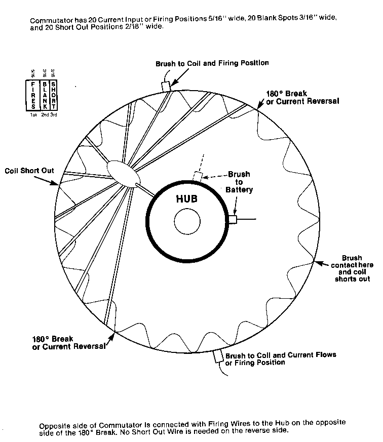
- Mechanical commutator opens/closes circuit at specific rotor angles
- Back-EMF spikes are harvested to recharge a battery or capacitor
Energy Sources
Applications
- Standalone power generation
- Motor drives for low-speed applications
- Battery recharging via back-EMF
Claimed Performance
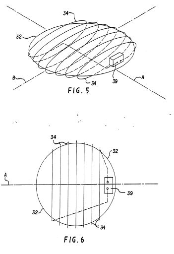
Higher energy output than input; motor speed ~=230 RPM; coil inductance 220 H, resistance 17 kOmega; pulsed coil voltage ~=300 V DC with back-EMF spikes up to 1500 V; efficiency claimed >100 % in motor mode.
Experimental Evidence
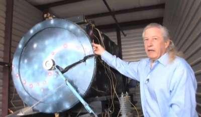
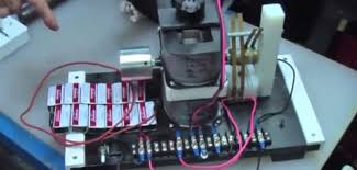
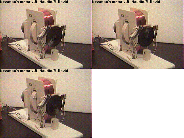
Preliminary test run (06-17-98) showing motor operation; multiple video demonstrations; independent replication video by Geoffrey Miller; voltage and current waveforms shown on oscilloscope.
Replication Status
Demonstrated by independent video replication (Geoffrey Miller) and by other hobbyists.
Limitations
- Claims rely on preliminary, non-peer-reviewed data
- High voltage spikes require careful safety measures
- Precise mechanical tuning of commutator is critical
- Scalability and long-term reliability not demonstrated
Red Flags
- Overunity claim without independent, reproducible verification
- Preliminary test results only, no peer-reviewed publication
- Potential for misinterpretation of back-EMF as net energy gain