Goal
Reduce size, weight, cost, friction and vibration of reciprocating pumps/engines while providing variable displacement and near-perfect balancing.
Problem
Conventional crankshaft and connecting-rod systems are bulky, heavy, expensive, generate high side loads, friction and vibration, and require complex bearing arrangements.
Concept Summary
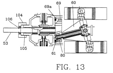
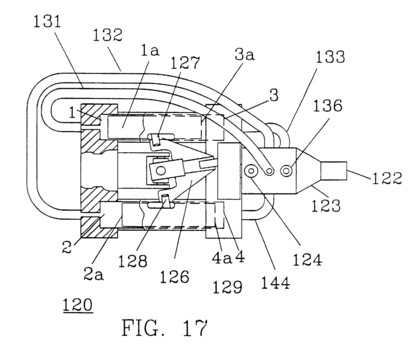
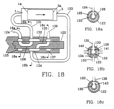
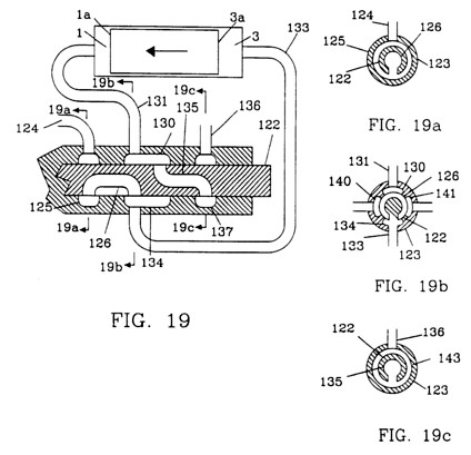
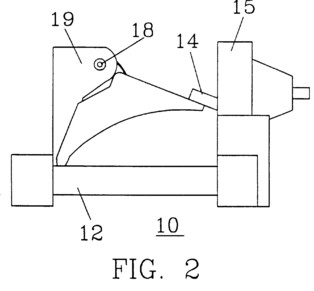
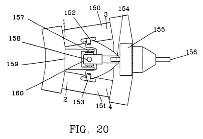
The Sanderson Mechanism replaces the crankshaft with a centrally supported U-joint and a transition arm that transmits rotary motion from a flywheel to multiple double-ended pistons via radial pins. Stroke is varied by changing the offset of a bushing on the flywheel or by moving the main shaft laterally. The design eliminates split-bearing assemblies, reduces side loads, and achieves near-sinusoidal motion, resulting in a compact, low-vibration, low-cost pump/engine.
Detailed Description
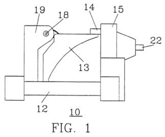
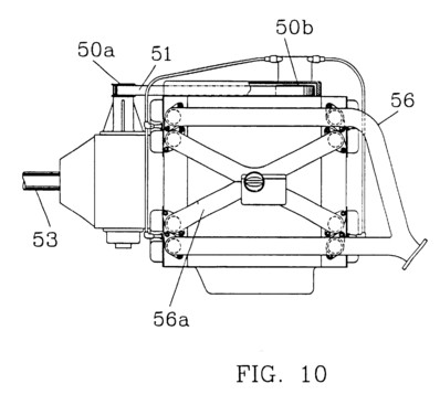
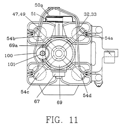
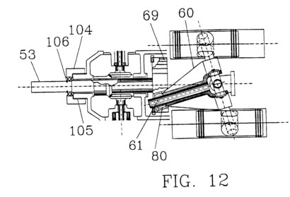
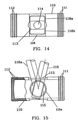
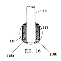
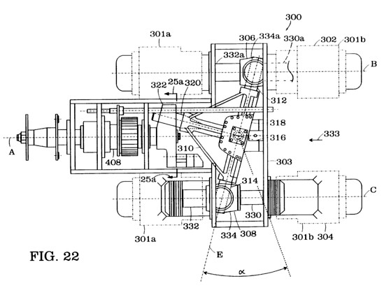
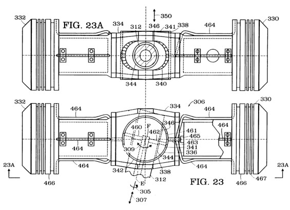
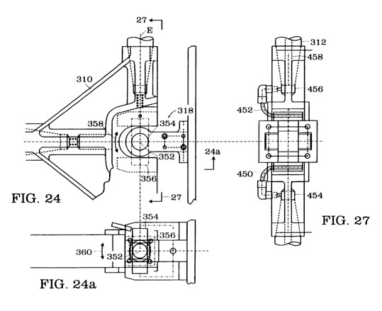
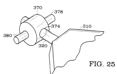
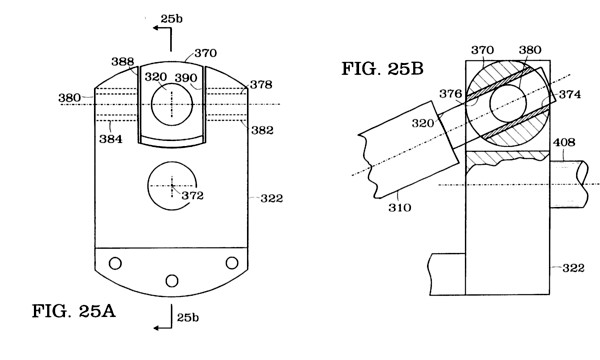
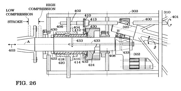
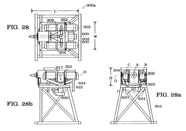
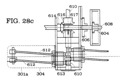
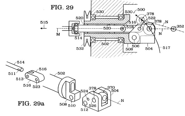
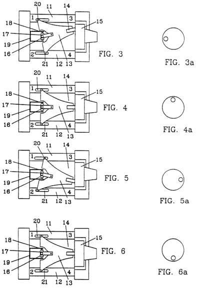
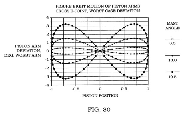
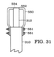
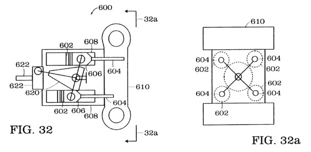
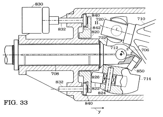
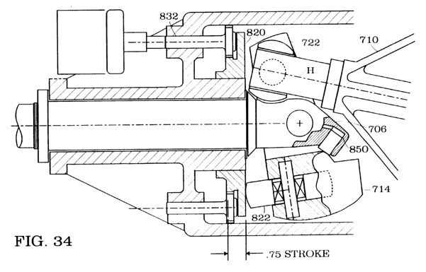
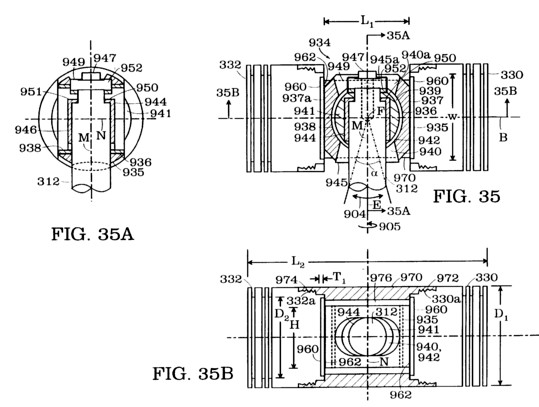
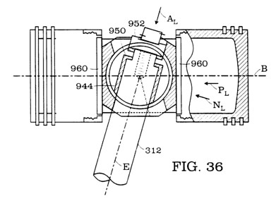
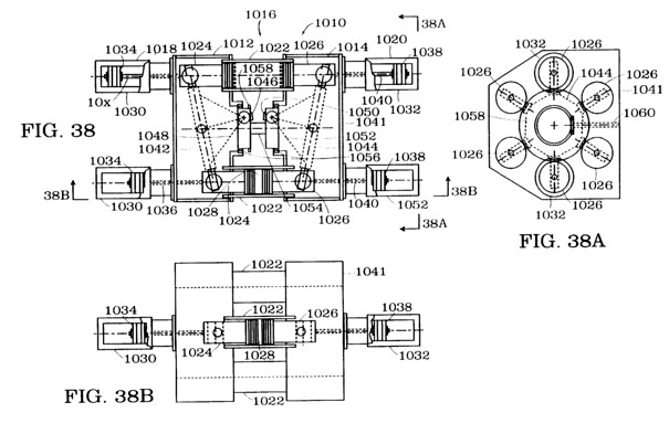
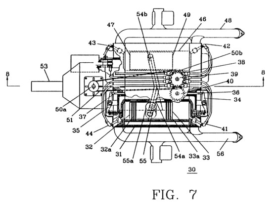
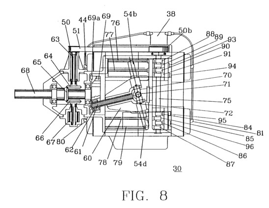
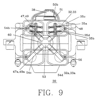
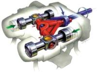
A perspective drawing shows a four-cylinder device formed by two double-ended pistons. The transition arm is supported by a U-joint; pins project radially 180 deg apart to drive the pistons. A nose pin on the arm receives rotary motion from an offset bushing on the flywheel. By moving the flywheel or adjusting the bushing offset, the stroke can be changed (prototype demonstrated 6:1 to 12:1). The mechanism uses off-the-shelf press-fit bearings, eliminates split-load bearings, and reduces friction by minimizing side forces. The balanced motion stays within 1 % of a pure sinusoid, allowing a single counterweight to balance the assembly. A 750-hp pump built with this mechanism is 66 % smaller in footprint, 40 % smaller in volume, 2,000 lb lighter, and operates at 20 % lower speed than a comparable conventional pump.
Principles
- Conversion of rotary to linear motion via a transition arm
- Variable displacement through adjustable bushing offset
- Balanced sinusoidal motion
- Reduction of side loads and friction
- Use of U-joint for central support
Scientific Domains
Materials
- Steel (for pistons, arm, flywheel)
- Bearing steel
- Cast iron (possible housing)
- Standard off-the-shelf bearings
Mechanisms of Action
- Rotary motion of flywheel drives transition arm
- Transition arm pushes radial pins attached to pistons
- Adjustable offset changes lever arm length, altering stroke
- Elimination of crankshaft and connecting rods reduces mass and friction
- Balanced motion reduces vibration and bearing wear
Energy Sources
Applications
- Hydraulic pumps
- Vehicle powertrain (hydraulic hybrid)
- Industrial compressors
- Marine and aerospace pumps
Claimed Performance
60 % reduction in size & weight, footprint reduced by 66 %, volume reduced by 40 %, weight reduction of ~2,000 lb for a 750-hp pump, 20 % lower operating speed for same output, near-perfect balancing (within 1 % sinusoidal), variable stroke from 6:1 to 12:1 demonstrated on prototype.
Experimental Evidence
Prototype engine varied stroke from 6:1 to 12:1 while operating. A 750-hp pump built with the mechanism showed 66 % smaller footprint, 40 % smaller volume, and 2,000 lb weight reduction compared with a conventional pump.
Replication Status
Prototype demonstrated; licensing information available.
Limitations
- Design limited to even numbers of pistons
- Maximum practical cylinder count around seven
- Prototype only; not yet mass-produced
- Stroke range limited by geometry of offset bushing