Goal
To use living trees as natural, low-cost antennas for radio receiving and transmitting, providing reliable communication in forested or remote locations.
Problem
The need for effective, inexpensive antenna structures where conventional metal masts are impractical, especially for military and amateur radio use.
Concept Summary
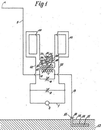
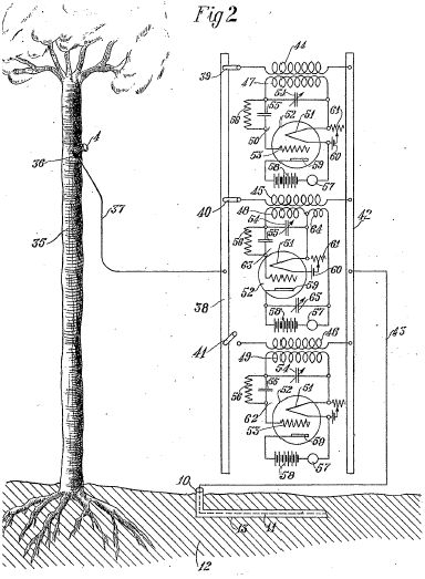
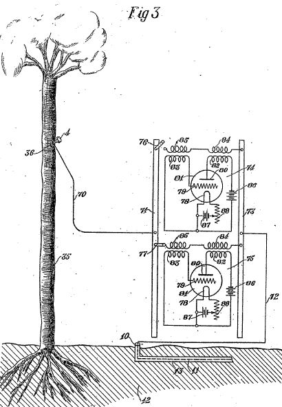
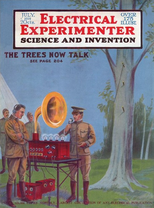
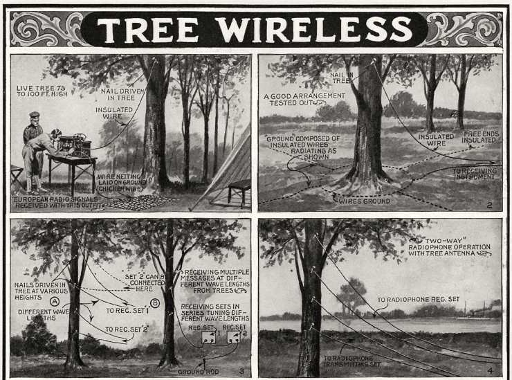
A metallic nail is driven into a tree at approximately two-thirds of its height; an insulated wire is attached to the nail and connected to a radio receiver or transmitter. The tree acts as a conductive aerial, coupling electromagnetic waves from the atmosphere to the receiver or radiating them from the transmitter.
Detailed Description
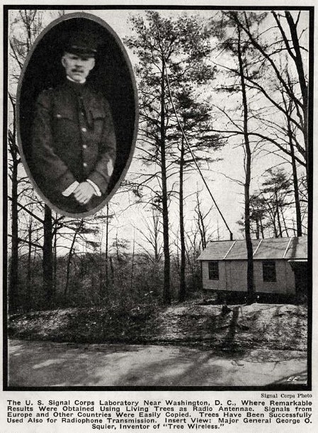
The method involves climbing a tree to about 66 % of its total height, driving a copper (or any metal) nail a few inches into the trunk, and hanging a wire from the nail. The wire is then connected to the radio set's antenna input. Multiple nails (up to 6-8) may be used to increase signal strength, but diminishing returns are observed beyond six. A small wire netting placed on the ground beneath the tree serves as a ground plane. The system works with various tree species (oak, pine, eucalyptus) and performs best when the tree is alive, leafy, and in dry clear weather. Experiments demonstrated reception of European stations (e.g., Nauen, New Brunswick) and two-way telephonic communication with low transmitting current. The technique was tested by the U.S. Army Signal Corps during World War I and reported in Scientific American (1919).
Principles
- Electromagnetic wave propagation
- Antenna theory (height and ground plane effects)
- Conductive coupling through living wood
Scientific Domains
Materials
- Living tree (any species, preferably leafy and healthy)
- Metal nail (copper preferred, non-rusting)
- Insulated copper or aluminum wire
- Ground-plane wire netting (optional)
Mechanisms of Action
- Tree acts as a natural conductive mast, raising the effective antenna height
- Metallic nail provides a low-impedance electrical contact to the tree's internal water-rich tissues
- Insulated wire carries the induced RF voltage to the receiver or feeds the transmitter
Energy Sources
Applications
- Military field communications
- Amateur radio reception in forested areas
- Emergency or disaster communication where conventional antennas are unavailable
Claimed Performance
Strong, full-toned reception of European stations (e.g., Nauen, Lyons, Poldhu) and clear two-way telephonic communication with remarkably low transmitting antenna current.
Experimental Evidence
Signal Corps field tests during WWI reported successful reception of multiple European stations through oak, pine, and eucalyptus trees, as well as two-way telephony over short distances. The nail-wire arrangement was shown to be essential; disconnecting the wire caused signal loss.
Replication Status
Demonstrated in U.S. Army Signal Corps laboratories and field stations; no independent civilian replication documented in the article.
Limitations
- Dead or leafless trees are ineffective
- Performance degrades in damp or rainy weather
- Limited transmitting range (short distances demonstrated)
- Dependence on tree species and health
Red Flags
- Lack of peer-reviewed, independent replication
- Potential for covert use as an undetectable antenna in hostile environments