Goal
Provide a very compact AM broadcast antenna with high efficiency, high gain and broad bandwidth, eliminating the need for large ground-radial systems.
Problem
Conventional AM broadcast antennas are physically large (~=1/4 wavelength), require extensive ground radials, have limited bandwidth and lower efficiency.
Concept Summary
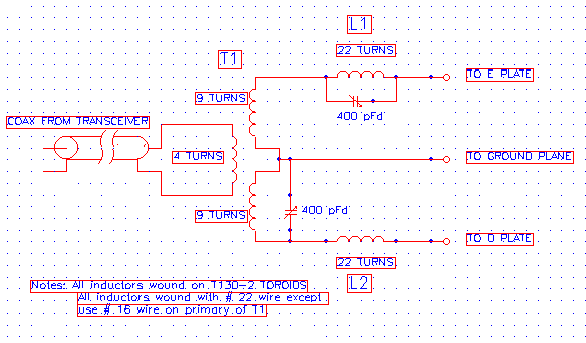
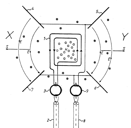
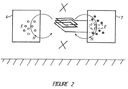
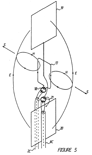
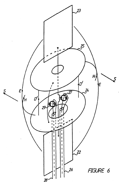
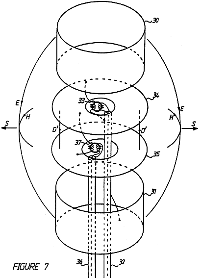
The CFA synthesises a radiated electromagnetic wave by generating electric and magnetic fields in separate, non-resonant metal structures (capacitor plates and short cylinders). A RF power source drives both structures through a phasing network so that the E- and H-fields are cross-stressed in phase, producing a synchronized Poynting vector in a small interaction zone and radiating efficiently from a volume orders of magnitude smaller than a conventional antenna.
Detailed Description
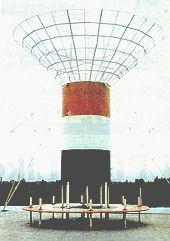
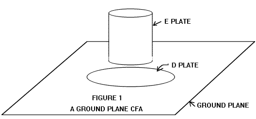
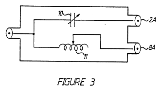
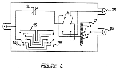
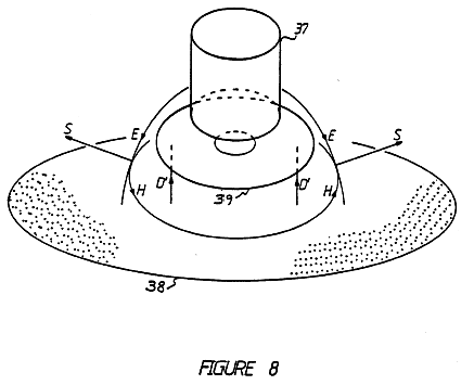
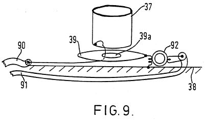
Two parallel capacitor plates (the "D plates") form a high-voltage electric field when driven by RF power. Above and below these plates sit short metal cylinders (the "E plates") that carry a displacement current, generating a magnetic field. A power divider/phasing network splits the transmitter output and adjusts the relative phase so that the electric and magnetic fields are in quadrature and overlap in the interaction region. The resulting E*H synchronism creates a rotational Poynting vector that radiates. Various configurations have been built: a barrel-shaped CFA, a ground-plane version, and a funnel-top version with a 21-ft height (~=0.025 λ) that reportedly yields a 9 dB advantage over a conventional quarter-wave vertical. Field tests in Egypt at 1161 kHz with 60 kW input, and later at 30 kW, demonstrated the claimed gain and bandwidth.
Principles
- Reversed (negative-solution) form of Maxwell's fourth equation
- Displacement current in a capacitor
- Poynting vector synthesis (E*H synchronism)
- Phase-synchronised feeding of separate E- and H-field generators
Scientific Domains
Materials
- Metal plates (conductive surfaces)
- Metal cylinders (conductors)
- Coils or parallel electrodes for displacement current
Mechanisms of Action
- RF voltage applied across parallel plates creates a strong electric field
- RF current in short cylinders creates a displacement current that generates a magnetic field
- Phasing network aligns the phases of the E- and H-fields
- Cross-stressed fields produce a rotating Poynting vector that radiates
Energy Sources
Applications
- AM broadcast transmission
- Radio broadcasting
- Telecommunications
Claimed Performance
Typical gain ~=6 dB (400 %) over a conventional quarter-wave vertical; up to 9 dB (800 %) advantage reported for funnel-top design; operates at 1161 kHz with 60 kW input; four operational units in Egypt ranging from 5 kW to 110 kW.
Experimental Evidence
Field tests in Egypt on 1161 kHz at 60 kW; funnel-top CFA tested at 30 kW showing 9 dB gain; four antennas currently broadcasting in Egypt (22 kW, 100 kW, 110 kW, 5 kW).
Replication Status
Four CFA installations reported on air in Egypt; multiple configurations built and tested by the inventors and collaborators.
Limitations
- Performance claims rely on precise phase control and high-quality RF feeding
- Demonstrated only at specific medium-wave frequencies
- Independent peer-reviewed verification is lacking
Red Flags
- Extraordinary gain (6-9 dB) over a quarter-wave vertical with a much smaller physical size
- Claims based on a reversed form of Maxwell's equation without widespread acceptance
- Limited independent testing; most data come from the inventors' own measurements