Colin Ross : Eye Ray Detector

**[rexresearch.com](http://www.rexresearch.com/)
[rexresearch1.com](http://rexresearch1.com/)**
---
**Colin A. ROSS** **Eye Ray Detector**
---
**Related
: [Charles
RUSS --Eye Ray Detector](../RussEyeRayDetector/RussEyeRayDetector.htm)**
---
**
**
**Patent Application for Human Eyebeam Detection
System Now Available on U.S. Patent Office Web Page**
**DALLAS, TX -**
Noted psychiatrist and author Colin A. Ross, M.D., today
announced his patent application for a system to detect the
electromagnetic energy emitted by the human eye. Dr. Ross has
been researching a new science and medicine focused on the
human body's electromagnetic field, which will be detailed in
an upcoming book, "Human Energy Fields."
In his research, Dr.
Ross has discovered proof that the eye emits electromagnetic
energy that he calls an "eyebeam." He calls his invention an
Electromagnetic Beam Detection System for which he has filed
an application with the U.S. Patent and Trademark Office.
"The experimental
proof of the reality of the human eyebeam is crucial in
developing the science of human energy fields," said Dr. Ross.
"The existence of the human eyebeam has been dismissed by
psychologists, physiologists, physicists and virtually all
modern scientists. This represents a big step forward."
Dr. Ross' patent
application for the EBDS can be viewed at:
http://patft.uspto.gov/ Click on: Publication Number Search
Enter: 20090046246
Dr. Ross has also
filed an international Patent Cooperation Treaty application.
This is a step toward getting a patent in countries outside
the United States.
In a written
opinion, the International Searching Authority concluded that
all aspects of Dr. Ross' invention are novel, are inventive
steps and have industrial applications: "The industrial
applicability of claims 1-25 is self-evident in the sense of
PCT Article 33(4) because the subject matter claimed can be
made or used in industry."
According to Dr.
Ross' application, the electromagnetic beam detection system
can be used as a switch and can turn on or off any electrical
device. It functions like a clapper light, but uses the
electromagnetic energy emitted through the eyes instead of the
sound of a hand clapping.
Dr. Ross has sent
the link for the U.S. Patent Office application to James Randi
**(www.randi.org)** and is waiting to hear from him about
the status of his $1 Million Paranormal Challenge, in which he
claims that he can make a tone sound out of a computer using a
beam of energy he sends out through his eyes. Dr. Ross'
proposed Challenge protocol is available on his web site **(www.rossinst.com).**
---
[**http://www.rossinst.com**](http://www.rossinst.com/)
**The
Colin A. Ross Institute**

The Colin A. Ross
Institute was formed in 1995 to further the understanding of
psychological trauma and its consequences by providing
educational services, research, and clinical treatment of
trauma based disorders.
Educational services
are provided through workshops, books, CD's and DVD's. Dr.
Ross has published 130 papers in peer-reviewed journals, most
of them dealing with trauma and dissociation. Most of the
papers contain original research data, and much of the
research has been funded by the Ross Institute.
Dr. Ross consults to
three Trauma Programs at hospitals in Texas, Michigan and
California. Treatment at these programs is based on his Trauma
Model.
---
---
**ELECTROMAGNETIC BEAM DETECTION SYSTEM**
**US7806527
// WO2009025932**
**[
[PDF](US7806527B2.pdf) ]**
The present invention provides for a Line of Sight (LOS)
electromagnetic beam (EM) detection system configured with an
enclosure, a detection device, a processing device, a storage
device, and a communication device. The enclosure may or may
not be electromagnetically shielded from the surrounding
environment. The enclosure may contain one or more detection
devices and one or more portals configured for a user to look
through. The detection devices may be a non-contacting,
active-dry electroencephalogram (EEG) electrode or a high
input impedance EEG electrode. The processing device may be a
specifically programmed general purpose computer. The
communication device may be auditory and/or visual. The
storage device may store signals from the detection device for
later analysis and statistical manipulation. In some
embodiments, the LOS detection system may be used as a switch
responding to interaction with a LOS beam emanating from an
ocular cavity.
**BACKGROUND OF THE INVENTION
1. Field of the Invention**The present invention relates to an electromagnetic
detection system for the non-contacting detection of
electromagnetic fields emanating from a living organism and,
more particularly, to the detection of electromagnetic fields
emanating from an ocular cavity.
**2. Description of the Related Art**
All biological systems generate electromagnetic fields (EMF)
and these fields interact with and are affected by the
magnetic field surrounding the earth as well as other sources
of EMF such as solar flares. The human body in particular
generates a relatively complex electromagnetic field.
Measuring, sensing, and detecting the electromagnetic field
may provide important information for understanding the inner
workings and the treatment of the human body. There currently
exist known methods of measuring the electromagnetic field of
a body. The electromagnetic field generated by the brain, for
example, can be measured with a highly sensitive instrument
such as a Superconducting Quantum Interference Device (SQUID)
magnetometer. However, since the magnetic field generated by
the brain is on the order of roughly one billion times weaker
than the main magnetic field of the earth, most SQUID
magnetometers are typically housed in magnetically insulated
rooms in order to eliminate the background noise that would
otherwise overwhelm the signal from the brain. Such full-size
rooms can cost approximately $250,000 to construct and a SQUID
magnetometer capable of taking a full brain map costs about $2
million.
A less costly way to measure the electrical field generated by
the brain is through the use of a contacting
electroencephalogram (EEG) system. A simple EEG software
program and the necessary leads and electrodes can be
purchased for about $1,200 and run on a laptop computer. A
system such as this is commonly used during biofeedback
treatment by psychologists. Biofeedback is the process of
monitoring a physiological signal, and amplifying,
conditioning, and displaying the signal to the monitored
subject so that he or she can observe small changes in the
signal. Gradually, through trial and error, the monitored
subject may learn to affect certain biological or
physiological processes by associating certain actions with
the subsequent changes in the monitored signal.
Additionally, in some situations the measurement of electric
fields produced by the body may be useful in identifying
certain medical conditions or in the development of medical
treatments. For example, a typical application involves the
measurement of the electrical field of the heart through the
use of a contacting electrocardiogram (ECG or EKG). The
printout of the measurement may be used in making a number of
different diagnoses, including the likelihood of a heart
attack, and the identification of abnormal electrical
conduction within the heart, among others. Another application
involves the measurement of an electromagnetic beam emanating
from the ocular region of a human head. This electromagnetic
beam is essentially a line of sight (LOS) beam able to focus
an electromagnetic field on whatever the person is looking at.
However, traditional methods of attaching an electrode to
contact the surface of the skin in order to measure the
electromagnetic field are difficult due to the sensitive
nature of the eyes. Therefore, there exists a need for a low
cost, non-contacting measurement device configured to detect
and respond to the LOS beam. **SUMMARY OF THE INVENTION**The present invention provides a system for detecting an
electromagnetic beam. The system may comprise an enclosure
configured to facilitate visual access for an eye and
containing a detecting device comprising at least one
electrode. The system may further comprise a processing device
configured to receive an output from the detecting device.
Additionally, the system may comprise a communication device
configured to provide feedback communication corresponding to
the output from the detecting device.
**BRIEF DESCRIPTION OF THE DRAWINGS**For a more complete understanding of the present invention
and the advantages thereof, reference is now made to the
following Detailed Description taken in conjunction with the
accompanying drawings, in which:
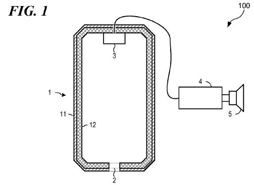
FIG. 1 illustrates an embodiment of an electromagnetic LOS
beam detection system configured according to the present
invention;
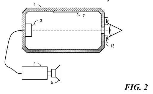
FIG. 2 illustrates an application of the electromagnetic LOS
beam detection system of FIG. 1;
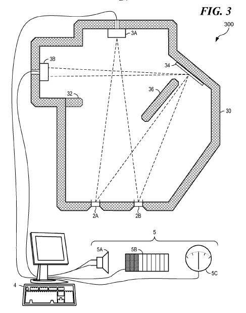
FIG. 3 illustrates another embodiment of an electromagnetic
LOS beam detection system configured according to the present
invention;
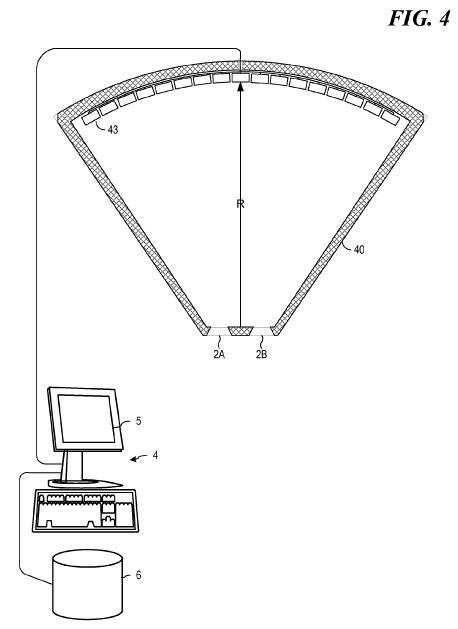
FIG. 4 illustrates another embodiment of an electromagnetic
LOS beam detection system configured according to the present
invention;
FIG. 5A illustrates a side view of another embodiment of an
electromagnetic LOS beam detection system configured according
to the present invention; and
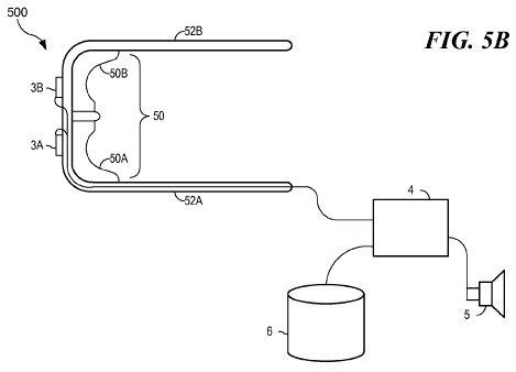
FIG. 5B illustrates a top view of the embodiment of FIG. 5A.
****
****
****
****
**** **DETAILED DESCRIPTION**In the following discussion, numerous specific details are
set forth to provide a thorough understanding of the present
invention. However, those skilled in the art will appreciate
that the present invention may be practiced without such
specific details. In other instances, well-known elements have
been illustrated in schematic or block diagram form in order
not to obscure the present invention in unnecessary detail.
Additionally, for the most part, details concerning network
communications, electromagnetic signaling techniques, and the
like, have been omitted inasmuch as such details are not
considered necessary to obtain a complete understanding of the
present invention, and are considered to be within the
understanding of persons of ordinary skill in the relevant
art.
Turning now to FIG. 1, the reference numeral 100 generally
indicates an illustrative example of an embodiment of an
electromagnetic line of sight (LOS) beam detection system 100
configured according to at least some aspects of the current
invention. The LOS beam detection system 100 may comprise an
enclosure 1, detection device 3, processing device 4, and a
feedback device 5. The components of the LOS beam detection
system 100 will be described in more detail in the following.
The enclosure 1 may completely surround a detection device 3
and may be electromagnetically (EM) shielded. An EM shielded
enclosure 1 may facilitate the filtering out or elimination of
background electromagnetic interference or noise typically
present in the environment. The enclosure 1 may be configured
in a variety of shapes and sizes, not limited to the
illustrative example shown. In some embodiments, the enclosure
1 may be in the form of a hand-held device approximately the
size and shape of a pair of binoculars, among others. As shown
in FIG. 1, a relatively simple enclosure approximately in the
shape of a sealed cylinder, among others, may be used for the
enclosure 1.
An EM shielded enclosure 1 may comprise a central core
structure 12 overlaid with an electromagnetic shielding
material 11 or in some cases, may be directly formed from the
shielding material 11. The central core structure 12 may be
formed from any of a wide variety of lightweight and/or low
cost materials, such as polypropylene, aluminum, cardboard or
other compressed fiber material, and wood, among others. Some
examples of shielding material 11 include mu-metal, a
nickel-iron alloy comprising approximately 75% nickel, 15%
iron, plus copper and molybdenum, among others. Mu-metal has a
very high magnetic permeability and may be very effective at
screening static or low-frequency magnetic fields. Other
materials that may exhibit similar properties include
supermalloy, supermumetal, nilomag, sanbold, and Mo-permalloy,
among others. The examples listed are not intended to form an
exhaustive list but are instead intended to illustrate a
representative selection from a wide variety of appropriate
materials.
The enclosure 1 may comprise one or more portals 2 (i.e.,
openings) configured to provide visual access for a
corresponding number of eyes. In the embodiment shown in FIG.
1, a single portal 1 may be provided for a single eye of a
monitored subject. In other embodiments, two portals may be
provided for both eyes of a single monitored subject. With
larger devices, 2 or more portals may be provided for two or
more monitored subjects simultaneously undergoing monitoring.
The portal 2 may be covered with a transparent member such as
glass, plastic, acrylic, or other non-electromagnetic
shielding material, among others, so as to completely enclose
the interior of the enclosure 1. In some cases, the portal 2
may be open, eliminating any obstruction between the LOS beam
and the detection device 3. The exterior surface surrounding
the portal 2 may be configured to comfortably accommodate the
surrounding structure of an eye, including but not limited to,
a resilient interface 13 (FIG. 2) such as a foam surround or
camera type of rubber eyepiece for example, among others. The
resilient interface 13 may also comprise EM shielding material
to reduce or further inhibit the passage of electromagnetic
background noise or interference into the interior chamber of
the enclosure 1.
The detection device 3 may be a non-contacting, active-dry
electroencephalogram (EEG) electrode configured to measure
electrical signals from the brain. Conventional EEG electrodes
may have input impedances up to an order of about 10<6>?
to 10<7>?. A detection device 3 comprising conventional
EEG electrodes may require EM shielding surrounding the
enclosure 1 to reduce interference from surrounding
electromagnetic and other noise. The length of the enclosure 1
may be designed to correspond with the ability of the EEG
electrode to remotely sense the LOS beam. The non-contacting,
active-dry EEG electrode may comprise tin, gold, silver, or
other appropriate materials, in addition to combinations of
these materials, configured as discs.
Alternatively, the detection device 3 may be a high (or
ultra-high) impedance EEG electrode. A high impedance EEG
electrode may have an input impedance from about 10<7>?
up to approximately 10<15>?. The noise floors of high
impedance EEG electrodes may be on the order of approximately
70 ?V Hzat 1 Hz. Due at least in part to the low
noise levels achievable with high impedance EEG electrodes, a
LOS beam detection system 100 may require only modest, if any
at all, electromagnetic shielding for the enclosure 1, even at
the highest levels of sensitivity, when the detection device 3
comprises one or more high impedance EEG electrodes. An
optimization between the cost of the high impedance EEG
electrodes and the cost of the electromagnetic shielding may
drive the overall configuration of the LOS beam detection
system 100. As with the other EEG electrodes comprising the
detection device 3, the length of the enclosure 1 may be
designed to correspond with the ability of the high impedance
EEG electrode (or other embodiment of the detection device 3)
to remotely sense the LOS beam.
The detection device 3 may be coupled with a processing device
4. The processing device 4 may comprise a specifically
programmed general purpose micro-processor, a purpose built
device with application specific instruction code, or a
combination of various components working together as a
system, among other embodiments. For example, a commercially
available multi-channel, multi-modality encoder may be
connected through a USB port to a general purpose computer
running appropriate software. The computer may receive the
signal and amplify or otherwise convert the signal into a
communicative feedback. The communicative feedback may
comprise a visual display such as illuminating various amounts
and/or colors of lights, graphs, and shapes, among others.
Alternatively, or in addition to the visual display, the
communicative feedback may comprise an audio component, such
as various frequencies of tone, various frequencies or
intervals of tonal bursts (e.g., such as in a traditional
Geiger counter, etc.), and/or synthesized speech reacting to
the detected LOS beam, among others. The communicative
feedback may be via the processing device 4 (e.g., through the
display or speakers typically integrated with a general
processing computer), or via external devices (such as a stand
alone communication device 5) driven by or coupled to the
processing device 4. In all communications between various
components, the connections may either be hardwired, wireless
(e.g., Bluetooth(r), Wi-Fi), or a combination of various
transmission methods and systems, among others.
A communication device 5 may be coupled to the processing
device 4. The communication device 5 is shown as a speaker
only for the purposes of illustration. Many forms and methods
of communicating the strength of the feedback signal from the
detection device 3 may be used in place of the speaker shown
as a communication device 5. One or more speakers or a more
ergonomic form of speaker such as headphones, ear plugs, etc.,
may be used as an embodiment of the communication device 5.
The communication method described in this illustrative
embodiment may involve some form of auditory communication so
that a monitored subject may not have to avert their eyes from
the detection device 3 in order to receive the communicative
feedback.
Turning now to FIG. 2, a method for using the LOS beam
detection system 100 may be as follows. A LOS beam detection
system 100 may be configured as described above, comprising an
enclosure 1, a detection device 3, a processing device 4, and
a communication device 5. In certain illustrative embodiments,
the interior of the enclosure 1 may contain an illuminating
device 7 configured to facilitate the visual detection of
detection device 3 during use of the LOS beam detection system
100. Alternatively, or in addition to the illuminating device
7, at least a portion of the enclosure 1 may comprise a
transparent or semi-transparent section enabling visual
communication with the detection device 3 contained within the
enclosure 1.
The subject may place their eye proximate to the portal 2 such
that there may be a substantially direct line of sight
communication between the detection device 3 and their eye
(shown by a broken line). For example, the subject may place
at least a portion of the area surrounding their eye directly
against the resilient interface 13. The processing device 4
may process the signal from the detection device 3 and may
provide a processed signal to the communication device 5. The
subject may then alter physiological and/or mental aspects of
their body and concentration in an attempt to manipulate the
signal to a maximum level. Such alterations may include
increasing or decreasing focus on the detection device 3,
varying concentration efforts and levels, and relaxing or
tensing the musculature surrounding the eye, among other
techniques.
Another form of use may involve the monitored subject
alternating between directly looking at the detection device 3
and not looking at the detection device 3. Not looking at the
detection device 3 may involve altering the line of sight to
one side or another of the detection device 3 and/or closing
the eye proximate to the portal. In some cases, both looking
to one side and closing the eye may be used. The subject may
try to alter the communicative feedback from the communication
device 5 through a range of on (e.g., some auditory feedback)
when looking at the detection device 3, to off when not
looking at the detection device 3. The LOS beam detection
system 100 may also be used as a passive monitoring system for
acquiring data regarding the electromagnetic waves traveling
through an ocular region of the head.
**Another Embodiment**
Referring now to FIG. 3, the reference numeral 300 generally
indicates another illustrative embodiment of the LOS beam
detection system 300 configured according to at least some
aspects of the present invention. In this figure, similar
components may be given the same reference numbers and a
detailed description of these components may not be repeated.
The LOS beam detection system 300 may comprise an enclosure
30, a first and second portal 2A and 2B, a first and second
detection device 3A and 3B, a reflector member 34, a
processing device 4, and a communication device 5 shown a
speaker 5A, illuminated bar graph 5B, and a meter 5C. The
various components of the LOS beam detection system 300 will
be described in greater detail below.
The enclosure 30 of the LOS beam detection system 300 may be
configured to accommodate a first and second portal 2A and 2B,
for each eye of a single monitored subject for example. In
some applications, two monitored subjects may each use one of
the first and second portals 2A and 2B. However, although two
portals 2A and 2B are shown in this illustrative embodiment,
the current invention may not be limited to this
configuration. One portal or three or more portals may be used
with the enclosure 30. As with the previously described portal
2, the first and second portals 2A and 2B may be configured to
comfortably accommodate two eyes of a single subject. In some
embodiments, the first and second portals 2A and 2B may be
adjustable (e.g., towards and away from one another, an
adjustment system is not shown in this figure) in order to
adapt the LOS beam detection system 300 to a wide variety of
ages and body types of individual subjects.
As seen in FIG. 3, the enclosure 30 may also be configured to
accommodate two detection devices, such as a first detection
device 3A and a second detection device 3B. In this
illustrative embodiment, the first detection device 3A may be
along a line of sight for the first and second portals 2A and
2B. However, the second detection device 3B may be obstructed
from a direct line of sight via the first and second portals
2A and 2B. The obstruction for the second detection device 3B
may be due to a configuration of the enclosure 30 (e.g.,
locating the second detection device 3B within a bottomed
cylindrical cavity or around a bend in a wall for example,
among others), or the obstruction may be due to secondary
feature such as an internal wall 32 or some other form of
electromagnetic shielding for example. As shown, the second
detection device 3B may be at an angle to the first detection
device 3A.
In order to facilitate a line of sight communication between
the first and second portals 2A and 2B and the second
detection device 3B, the enclosure 30 may contain a reflective
member 34 positioned at an angle to the portals and the second
detection device 3B. The reflective member 34 may comprise a
optical and/or electromagnetic reflective material, among
others, enabling the portals 2A and 2B to have a visual and/or
electromagnetic beam direct line of sight communication with
the second detection device 3B. For example, some polished
metals may provide both forms of reflection for the reflective
member 34. In some embodiments, a secondary internal wall 36
or more may be provided within the enclosure 30 in order to
prevent cross contamination of the first and second detection
devices 3A and 3B (i.e., to ensure primary detection by the
first detection device 3A substantially when looking at the
first detection device 3A, and primary detection by the second
detection device 3B substantially when looking at the second
detection device 3B).
As with the previous enclosure 1, the enclosure 30 of the LOS
beam detection system 300 may be electromagnetically shielded
depending at least in part upon the amount of surrounding
environmental electrical noise and/or the input impedance
level of the electrodes comprising the first and second
detection devices 3A and 3B. The other details and materials
appropriate for the enclosure 1 may be applied for the
enclosure 30.
The first and second detection devices 3A and 3B may be
communicatively coupled with a processing device 4 that is in
turn communicatively coupled with one or more communication
devices 5. As shown in this illustrative embodiment, examples
of the communication devices 5 may include one or more
speakers 5A, one or more illuminated bar graphs 5B, and one or
more meters 5C, among others. The bar graphs 5B and the meters
5C may be stand alone components coupled to the processing
device 4, or they may be virtual components visually displayed
on a monitor. There may be a single communicative device 5 for
each of the detection devices 3A and 3B (e.g., using separate
frequency tones with a variable volume level for indicating
the strength and identity of a signal from the detection
devices 3A and 3B). However, a separate set of communication
devices 5 may be provided for each of the detection devices 3A
and 3B. In this case, each of the detection devices 3A and 3B
may be individually monitored by a subject and/or a
technician.
The LOS beam detection system 300 may be used to detect the
strength and application of a reflected LOS beam. A subject
may initially focus on the first detection device 3A and then
alternate by focusing on the second detection device 3B via
the reflective member 34. By receiving the communication
feedback from the communication devices 5, a monitored subject
may identify which detection device is receiving the LOS beam
and attempt to alter the strength of the LOS beam. After a
number of monitoring sessions with the first detection device
3A are recorded, such as in an electronic file or database of
the processing device 4, the subject may perform and record a
number of monitoring sessions with the second detection device
3B. Subsequently, statistical analysis may indicate the
relative strength of a reflected LOS beam as compared to a
direct LOS beam, among others.
**Another Embodiment**Turning now to FIG. 4, the reference numeral 400 generally
indicates another illustrative embodiment of the LOS beam
detection system 400 configured according to at least some
aspects of the present invention. In this figure, similar
components may be given the same reference numbers and a
detailed description of these components may not be repeated.
The LOS beam detection system 400 may comprise an enclosure
40, a first and second portal 2A and 2B, a plurality of
detection devices 43, a processing device 4, a communication
device 5, and a storage device 6. The various components of
the LOS beam detection system 400 will be described in greater
detail below.
In this illustrative embodiment of the present invention, a
plurality of detection devices 43 is contained within an
enclosure 40. The plurality of detection devices 43 may
preferably be located substantially equidistantly from the
first and second portals 2A and 2B, for example, such as along
a substantially constant radius from a center point between
the first and second portals 2A and 2B (as shown by the radius
R). The plurality of detection devices 43 are shown along a
single row for the purposes of illustration only. The
arrangement of the plurality of detection devices 43 may be
regular or irregular, in one, two, or three dimensions.
The plurality of detection devices may be coupled to a
processing device 4 integrated with a communication device 5,
for example. The communicative feedback for the plurality of
detection devices 43 may comprise a one or two dimensional
image composed of variable colors of light showing the
intensity of an individual signal at a location on a monitor
corresponding to the location within the enclosure 40 of the
particular detection device of the plurality of detection
devices 43. Video communication may be the preferred way to
communicate the plurality of signal streams to the subject
and/or an operator/technician. However, auditory communication
may still provide information including the average intensity
of the LOS beam (e.g., a volume level corresponding to the
highest signal strength) or the focus of the LOS beam (e.g., a
variable frequency corresponding to a ratio of the average
number of detection devices indicating the presence of a
signal versus the total number of the plurality of detection
devices). Alternatively, the communicative feedback of the
plurality of detection devices 43 may track the LOS beam as a
subject looks over the plurality of detection devices 43. For
example, the communicative signal may track as the subject
looks from side to side within the enclosure 40 or as the
subject attempts to vary the focus of the LOS beam.
The processing device 4 may be coupled to an internal and/or
external storage device 6, such as an electromagnetic,
optical, flash, or virtual storage device (i.e., storage
across various sites on the Internet), among others. The
signals from the plurality of detection devices 43 may be
stored for later retrieval and statistical processing and
analysis, as well as assisting medical professionals in the
monitoring and diagnosis of various illnesses and treatments.
**Another Embodiment**Referring now to FIGS. 5A and 5B, the reference numeral
500 generally indicates another illustrative embodiment of the
LOS beam detection system 500 configured according to at least
some aspects of the present invention. In this figure, similar
components may be given the same reference numbers and a
detailed description of these components may not be repeated.
The LOS beam detection system 500 may comprise an enclosure 50
comprising first and second enclosures 50A and 50B (only 50A
can be seen in FIG. 5A), an attachment member 52, detection
devices 3 comprising first and second detection devices 3A and
3B (only 3A can be seen in FIG. 5A), a processing device 4, a
communicative device 5, and a storage device 6. The various
components of the LOS beam detection system 500 will be
described in greater detail below.
The LOS beam detection system 500 shown in the figures may be
substantially configured in the form of a pair of glasses or
goggles. Since both sides of a pair of glasses are
substantially symmetrical, only one side needs to be described
in detail. The first enclosure 50A may fit around an eye in a
manner similar to the way one side of a pair of waterproof
goggles fits around an eye (e.g., forming a sealed environment
within the goggles). There may not be a dedicated portal in
this configuration because the first enclosure 50A may be open
on one side. The eye and surrounding tissue may form the final
wall of the first enclosure 50A. As with the previous
illustrative embodiments, the first enclosure 50A may be
electromagnetically shielded to prevent electrical noise and
interference from disrupting or altering the detection signal
from the first detection device 3A. In some embodiments, the
first enclosure 50A may be transparent to allow the subject to
visibly interact with their surroundings during the monitoring
processes. In this case, a first detection device 3A with a
high input impedance may be used.
The first detection device 3A may be located at any location
on or within the first enclosure 50A. Preferably, the first
detection device 3A may be located directly in the line of
sight of a subject when the subject is looking straight ahead
(e.g., indicated by the solid lines in FIG. 5A). However, in
some embodiments the first detection device 3A may be located
to one side or another of the first enclosure 50A (e.g., a
position not normally in the line of sight, indicated by the
broken lines in FIG. 5A). The LOS beam detection system 500
may function in this configuration as a switch, in which the
subject may signal a change in state by looking off to the
side, directly at the first detection device 3A. Whereas,
during normal interaction, the subject may be able to
substantially look around without triggering the first
detection device 3A.
The first detection device 3A may be coupled to a processing
device 4. The processing device may be internally or
externally integrated with a communication device 5 and/or a
storage device 6. Communicative feedback interaction and data
processing and storage may be the same or similar to the
previously discussed embodiments. The LOS beam detection
system 500 may offer an advantage in that the detection
devices 3 may be placed relatively close to the surface of the
ocular area, potentially increasing the strength of the LOS
beam received by each of the detection devices 3. In addition,
the LOS beam detection system 500 may be worn relatively
unobtrusively and conveniently, thereby permitting the
monitoring and/or signaling via the detection devices 3 in a
wide variety of environments and situations.
Having thus described the present invention by reference to
certain of its preferred embodiments, it is noted that the
embodiments disclosed are illustrative rather than limiting in
nature and that a wide range of variations, modifications,
changes, and substitutions are contemplated in the foregoing
disclosure. In some instances, some features of the present
invention may be employed without a corresponding use of the
other features. Many such variations and modifications may be
considered desirable by those skilled in the art based upon a
review of the foregoing description of preferred embodiments.
Accordingly, it is appropriate that the appended claims be
construed broadly and in a manner consistent with the scope of
the invention.
---
**WHOLE BODY ELECTROMAGNETIC DETECTION SYSTEM**
**WO2010077390
// US2010152602**
**[
[PDF](US2010152602A1.pdf)
]**
An apparatus and method for characterizing electrical
signals from a living organism comprising sensors configured
to be positioned to receive the electrical signals emanating
from a human signal source. A processor may be configured to
interpret readings made by the sensors to output a
characterization of the electrical signals.
**BACKGROUND OF THE INVENTION
[0001] 1. Field of the Invention**[0002] The present invention relates to an electromagnetic
detection system of the electromagnetic fields emanating from
a living organism and, more particularly, to the
characterization of electromagnetic fields emanating from the
human body.
**[0003] 2. Description of the Related Art**[0004] All biological systems generate electromagnetic
fields (EMF) and these fields interact with and are affected
by the magnetic field surrounding the earth as well as other
sources of EMF such as solar flares. The human body in
particular generates a relatively complex electromagnetic
field. There currently exist known methods of measuring the
electromagnetic field of a body. The electromagnetic field
generated by the brain, for example, can be measured with a
highly sensitive instrument such as a Superconducting Quantum
Interference Device (SQUID) magnetometer. However, since the
magnetic field generated by the brain is on the order of
roughly one billion times weaker than the main magnetic field
of the earth, most SQUID magnetometers are typically housed in
magnetically insulated rooms in order to eliminate the
background noise that would otherwise overwhelm the signal
from the brain. Such full-size rooms can cost approximately
$250,000 to construct and a SQUID magnetometer capable of
taking a full brain map costs about $2 million.
[0005] A less costly way to measure the electrical field
generated by the brain is through the use of a contacting
electroencephalogram (EEG) system. A simple EEG software
program and the necessary leads and electrodes can be
purchased for about $1,200 and run on a laptop computer. A
system such as this is commonly used during biofeedback
treatment by psychologists. Biofeedback is the process of
monitoring a physiological signal, and amplifying,
conditioning, and displaying the signal to the monitored
subject so that he or she can observe small changes in the
signal. Gradually, through trial and error, the monitored
subject may learn to affect certain biological or
physiological processes by associating certain actions with
the subsequent changes in the monitored signal.
[0006] Additionally, in some situations the measurement of
electric fields produced by certain portions of the body may
be useful in identifying certain medical conditions or in the
development of medical treatments. For example, a typical
application involves the measurement of the electrical field
of the heart through the use of a contacting electrocardiogram
(ECG or EKG). The printout of the measurement may be used in
making a number of different diagnoses, including the
likelihood of a heart attack, and the identification of
abnormal electrical conduction within the heart, among others.
These methods require that detection of the electrical field
be accomplished using a contacting sensor, such as an
electrode.
[0007] Researchers have developed electrical potential probes,
as a type of non-contact electrode that detects the electric
potentials of a living organism generated by electrical
currents of the body. Harland C. J., Electrical Potential
ProbesNew Directions in the Remote Sensing of the Human Body
Meas. Sci. Technol., Vol. 12 2002, pp. 163-169. These
electrodes do not require electrical charge contact with the
living organism to detect the electromagnetic fields emanating
from the body. These researchers have demonstrated that by
using ultra-high-impedance electrodes, the electrical field of
a heart (ECG) can be detected with the electrode at up to one
meter away from the body. The use of these non-contacting
electrodes has given medical researchers and practitioners the
option to detect the electrical field of living organisms in a
non-invasive manner.
**SUMMARY**[0008] An apparatus and method for characterizing
electrical signals emanating from a living organism are
provided, comprising an array of sensors configured to be
positioned to receive the electrical signals and deliver
readings corresponding to the electrical signals to a
processor for interpreting the readings.
**BRIEF DESCRIPTION OF DRAWINGS**[0009] For a more complete understanding of the present
invention and the advantages thereof, reference is now made to
the following Detailed Description taken in conjunction with
the accompanying drawings, in which:
[0010] FIG. 1 is a schematic of an embodiment of a whole body
scanner assembly;
[0011] FIG. 2 is a schematic of an embodiment of a system for
characterizing the EMF emanating from a human body.
[0012] FIG. 3A is a side view of an alternate embodiment of a
whole body scanner assembly;
[0013] FIGS. 3B-3D are side views of the whole body scanner
assembly of FIG. 3A showing a sensor carrier in three
different positions;
[0014] FIGS. 4A and 4B are a bottom view and a side view,
respectively, of one embodiment of a sensor carrier for the
whole body scanner assembly shown in FIG. 3A;
[0015] FIG. 5 is a perspective view of a hand held embodiment
of a whole body scanner assembly;
[0016] FIG. 6 is a perspective view of one embodiment of a
stationary electromagnetic scanner;
[0017] FIGS. 7A and 7B is a first and second bottom view of a
sensor housing;
[0018] FIG. 8 is a perspective view of a sensor housing having
a generally curved shape;
[0019] FIG. 9A is a first front view of an alternate
embodiment of a whole body scanner assembly comprising a head
covering for a human body;
[0020] FIG. 9B is a second front view of the embodiment of a
whole body scanner assembly shown in FIG. 9A showing the whole
body scanner coupled to a head portion of a human body;
[0021] FIG. 10 is a cross-sectional view of the whole body
scanner assembly shown in FIG. 9A taken along line 10-10, as
shown in FIG. 9A;
[0022] FIG. 11 is a cross-sectional view of the whole body
scanner assembly shown in FIG. 9A taken along line 11-11;
[0023] FIG. 12A is a front view of an embodiment of a whole
body scanner comprising a garment intended to be worn as a
shirt by a human subject;
[0024] FIG. 12B is a top view of the embodiment of the whole
body scanner shown in FIG. 12A;
[0025] FIG. 13A is a cross-sectional view of the garment shown
in FIG. 12 taken along line 13-13;
[0026] FIG. 13B is a zoomed view of section 13B of FIG. 13A;
and
[0027] FIG. 14 is a flow diagram of the operations of a method
for characterizing the electrical signals emanating from a
living organism.
**DETAILED DESCRIPTION**[0028] In the following discussion, numerous specific
details are set forth to provide a thorough understanding of
the present invention. However, those skilled in the art will
appreciate that the present invention may be practiced without
such specific details. In other instances, well-known elements
have been illustrated in schematic or block diagram form in
order not to obscure the present invention in unnecessary
detail. Additionally, for the most part, details concerning
network communications, electro-magnetic signaling techniques,
and the like, have been omitted inasmuch as such details are
not considered necessary to obtain a complete understanding of
the present invention, and are considered to be within the
understanding of persons of ordinary skill in the relevant
art.
[0029] Turning now to FIG. 1, there is shown an illustrative
schematic example of an embodiment of a whole body scanner
assembly 100 for receiving and detecting a plurality of
electrical body signals from a living organism. In the
embodiment shown, an 8-lead neurofeedback system 102
comprising a plurality of sensors, such as first electrode
104a, second electrode 104b, third electrode 104c, fourth
electrode 104d, fifth electrode 104e, sixth electrode 104f,
seventh electrode 104g, and eighth electrode 104h.
[0030] The electrodes 104a-104h may be configured to make
electrical contact with the surface skin of the human body.
Each electrode 104a-104h may be connected individually to one
or more target body portions of a human body 10. The target
body portions (collectively referred to as reference numeral
11) of the human body 10 may comprise nerve centers of the
human body where nerve activity and electromagnetic activity
may be relatively high.
[0031] The electrodes 104a-104h may be configured for
attachment to the human body 10. In some embodiments, the
electrodes may comprise voltage probes, such as silver metal
electrodes, pasted to the skin using an adhesive. An
electrolytic paste, such as silver chloride gel, may interface
between the skin and the electrode to detect the flow of
electric current in the skin.
[0032] In some embodiments, the electrodes 104a-104h may each
comprise an input impedance value sufficient to reliably
receive electrical signals at a distance D. The electrode 220
may have an input impedance value from about 10<7>? up
to approximately 10<15>?. By comparison, conventional
paste-on sensors have impedance values approximately in the
range of 10<6 >to 10<7>?.
[0033] It may be advantageous to utilize a high input
impedance electrode in the whole body scanner assembly 100.
Such electrodes may be used for on-body sensing, even though
the electrode remains electrically insulated from the skin.
The electrodes may not require a charge contact with a skin
surface of the human body, unlike conventional paste-on
sensors. The high input impedance electrodes may be taped to
the human body with adhesive tape. The electrodes may be used
in pairs to obtain a differential signal to eliminate unwanted
body noise sources of electrical activity. The noise floors of
high impedance electrical potential electrodes may be on the
order of approximately 4 ?V Hzto 70 ?V Hzat 1 Hz., depending on whether the electrodes are
single-ended or coupled for differential readings.
[0034] In the embodiment shown, only electrodes 104a-104e are
shown connected to the human body 10. It should be understood
by persons of ordinary skill in the art that the number of
electrodes used and attached may vary. Also, more than one
electrode may be attached to a single target body portion 11.
Each target body portion 11 may be accessed by a single-ended
or a coupled pair of electrons. In the embodiment shown in
FIG. 1, single-ended electrodes are utilized.
[0035] A first electrode 104a may be attached to a head
portion 12, such as a forehead, of the human body 10. A second
electrode 104b may be attached to a throat portion 14 of the
human body 10. A third electrode 104c may be attached to a
chest portion, such as cardiac plexus 16. A fourth electrode
104d may be attached to an upper abdomen portion, such as
celiac plexus 18. A fifth electrode 104e may be attached to
lower abdomen portion, such as sacral plexus 104e. Each
electrode 104a-104e may couple to a first end of each of lead
wires 130, 132, 134, 136, and 138.
[0036] The whole body scanner assembly 100, as shown in FIG.
1, may further comprise a receiver, such as an interface (IFC)
120, coupled to a second end of each the lead wires 130, 132,
134, 136, and 138. The IFC 120 may comprise a processor
configured for receiving data corresponding to readings from
the electrodes 104a-104h through each respective lead wire
130, 132, 134, 136, and 138. The processor of the IFC 120 may
include a computer readable storage medium configured to
embody software instructions for operating the processor. The
data received by the IFC 120 may correspond to the electrical
signals received from the portion of the body each respective
electrode 104a-104h is attached. In some embodiments, the IFC
120 may comprise a wireless receiver for receiving wireless
signals transmitted from the electrodes 104a-104h. In a
wireless configuration, the lead wires 130, 132, 134, 136, and
138 may not be needed. The IFC 120 may further process and
filter the body signals for transmission to a first computer
124.
[0037] Turning now to FIG. 2, there is shown a schematic
diagram of the components of a system for characterizing the
electromagnetic field emanating from a living organism such as
the human body 10. The system 150 may comprise sensor 152
configured to receive and detect electrical signals 154 from
the human body 10, which may comprise a signal source. The
electrical signals may originate from target body portions 11,
such as those described in FIG. 1. The sensor 152 may be a
contacting sensor, such as electrodes 104a-104h as described
in FIG. 1 or non-contacting sensors, as described later in
FIGS. 3A-8. The system 150 may comprise one or more
processors, such as the IFC 120 and first computer 124, where
IFC 120 has the functionality described in FIG. 1. The IFC 120
may be configured with a switching mechanism 151 to establish
an electrical connection to the sensor 154 for receiving the
readings of the electrical signals 154 from the sensor 154. In
some embodiments, the switching mechanism may be incorporated
into the sensor 152.
[0038] Referring now to FIGS. 1 and 2, the first computer 124
may receive processed signals from the IFC 120 via a first
connection 122. The first computer 124 may comprise a
processor configured for receiving software instructions and a
computer readable storage medium having software code for
giving instructions to the processor of the first computer. In
some embodiments, the computer readable storage medium may
comprise software instructions for interpreting the plurality
of body signals received from the electrodes 104a-104h. The
first computer 124 may take the processed information gathered
from the body signals 154 and transform them into waveforms,
numerical values corresponding to electrical and magnetic
characteristics of the body signals, such as voltage,
frequency and amplitude, or into a color-coded scheme, such as
a tomographic map of the body signals. The first computer 124
may further output the information to a computer display, a
printer, or other device configured receive and handle
outputted information, such as a hard drive, a flash drive, a
compact disc medium, or other medium for storing the data. The
data may be stored in various formats including image, video,
or database formats. It should be understood that the
functions of the IFC 120 and the first computer 124 may be
performed by one or more circuits or one or more processors
and may be located local or remote to the whole body scanner
100.
[0039] In those embodiments where the output is displayed to a
monitor or recorded to a video file, the display may represent
a real-time characterization of the body signals 154. The body
signals 154 may be displayed as static images, a series of
images, an average value with standard deviation over a period
of time, or a real-time fluctuating display. The images
outputted to the display may comprise one-, two-, three- or
multi-dimensional representations of the body signals 154. The
display may further be configured to show the effects of
environmental inputs, or stimuli, on the human body
electromagnetic field.
[0040] Turning now to FIG. 3A, there is shown another
embodiment for a whole body scanner assembly 200 for
interpreting received signals from the targeted portions (12,
14, 16, 18, and 20) of the human body 10. The whole body
scanner assembly 200 may comprise a sensor carrier 202. An
array of sensors 204, comprising a first electrode 220a, a
second electrode 220b, a third electrode 220c, a fourth
electrode 220d, a fifth electrode 220e, a sixth electrode
220f, and a seventh electrode 220g (shown collectively as
reference numeral 220 in FIG. 3A and individually in FIGS. 4A
and 4B) may be configured for mounting to a bottom surface 206
of the sensor carrier 204, such that a receiving portion of
each of the electrodes 220a-220g may face away from the bottom
surface 206. Seven electrodes 220a-220g are shown in FIGS. 5A
and 5B; however, it should be understood by a person of
ordinary skill in the art that more or less electrodes may be
utilized to characterize the electric signals emanating from
the human body 10.
[0041] The sensor carrier 202 may be mounted to a scanning
mechanism 208. The scanning mechanism 208 may be configured
for moving the sensor carrier 202 along a scanning path 4,
which in some embodiments may be parallel to a body axis 2.
The scanning path 4 may correspond to a substantially straight
line along which the sensor carrier 202 may travel when in
operation. It should be recognized by persons of ordinary
skill in the art that the scanning path 4 may comprise curved,
zig-zag, or other configurations, which may depend on the
target body portions 12, 14, 16, 18, and 20 of the human body
10.
[0042] The body axis 2 may correspond to a length of a human
body, such as from head to toe. The body axis 2 may further
comprise generally an axis of intended target body portions
12, 14, 16, 18, and 20 emanating body signals. In other
embodiments, the body axis 2 may be chosen differently to
facilitate receiving body signals from a different length of
the body.
[0043] Turning now to FIGS. 4A and 4B, there are shown a
bottom view and a side view, respectively, of one embodiment
of the sensor carrier 202. In FIG. 4A, the electrodes
220a-220g are shown set up in the sensor array 204. The sensor
array 204 shown is a relatively straight line of electrodes
220a-220g spanning a length A, as shown. Each of the
electrodes 220a-220g may be set at a gap B from each
respective neighboring electrode.
[0044] The sensor array 204 may have other geometric
configurations. The length A and the gap B may be varied to
achieve an optimum characterization of the electric field
emanation from the human body 10. In other embodiments, the
sensor array 204 may comprise sensors aligned in staggered or
aligned rows. The gap B between sensors may be optimized
depending on the target body portions. It should be recognized
by persons of ordinary skill in the art that the sensor
carrier 202 may be configured to allow for the configuration
of the sensor array 204 to be varied to meet individual
requirements of the human body 10.
[0045] In the embodiment shown in FIGS. 3A and 4A, the
scanning mechanism 208 may comprise tracks 210a and 210b for
receiving translation members 211a and 211b of the sensor
carrier 202. The translation members 211a and 211b may couple
into each respective track 210a and 210b. The translation
members 211a and 211b may be configured to receive a movement
force, such as a torque for moving the sensor carrier 202
along each track. The tracks 210a and 210b may be
substantially parallel, as shown in FIG. 4A. The movement
force may be applied to the translation members 211a and 211b
via a motor (not shown), or other known device such as a
pulley for generating a movement force.
[0046] As shown in FIG. 4B, the sensor carrier 202 may be
mounted at a distance D from a reference point such as the
human body 10 (as shown in FIGS. 3 and 4B) or a receiving
platform 214 (shown in FIG. 3). Turning to FIG. 3A, the
scanning mechanism 208 may comprise a support structure having
a plurality of support members 212 for setting the tracks 210a
and 210b at the distance D. In the embodiment shown, the
tracks 210a and 210b (not shown) have been set substantially
level relative to the receiving platform 214, so that when the
sensor carrier 202 travels along the scanning path 4 the
sensor carrier 202 may stay at substantially the distance D
from the target body portions 11. In this configuration, the
sensor carrier 202 may move along the tracks 210a and 210b at
substantially the same distance D from the human body 10. The
support members 212 may be configured to be adjustable to fix
the distance D.
[0047] Turning now to FIGS. 3B, 3C, and 3D, there are shown
side views of the whole body scanner assembly 200 of FIG. 3A
with the sensor carrier 202 shown in three positions. In FIG.
3B, the sensor carrier 202 is shown suspended substantially
above a lower leg portion of the human body 10. As described
in FIGS. 4A and 4B, the sensor carrier 202 may be moved along
the tracks 210A and 210B. In the embodiment shown, the sensor
carrier 202 may begin at the lower leg portion and travel
substantially parallel the body axis 2 (shown in FIG. 3A) and
along the scanning path 4 (shown in FIG. 3A) towards the head
portion 12. As shown in FIGS. 3C and 3D, the sensor carrier
202 may be actuated along the scanning path 4 and along the
body axis 2 to cross over the target body portions 20, 18, 16,
14, and 12. The sensor array 204 may take readings
corresponding to the electrical signals emanating from the
human body 10 as it travels at the distance D from the human
body 10. The sensor array 204 may be switched by a switching
mechanism 151 (as shown in FIG. 2) at a point along its travel
path to facilitate taking reading from the target body
portions.
[0048] The electrodes 220 of FIGS. 3A and 4B may each comprise
a non-contacting electrode configured to receive signals from
an emanating source without requiring electrical or physical
contact, such as charge current contact, with the source. In
some embodiments, each electrode 220 may comprise an input
impedance value sufficient to reliably receive electrical
signals at a distance of up to one meter. The electrode 220
may have an input impedance from about 10<7>? up to
approximately 10<15>?. The noise floors of high
impedance electrodes may be on the order of approximately 4 ?V
Hz-70 ?V Hzat 1 Hz, depending on how
the electrodes are configured. The use of electrode 220 may
allow the detection of body electrical signals in a
non-invasive manner.
[0049] In the embodiment shown, the electrodes may operate to
make a single-ended reading, where there is no charge current
contact with the human body and the human body is not
grounded. Each electrode may function independently to
remotely detect electric potentials created within the human
body by electrical activity. In other embodiments, the
electrodes may operate in coupled pairs to make readings of
the electrical signals based off of differential signals. The
noise floor may vary from 4 ?V Hzat 1 Hz when
using single ended electrodes to 70 ?V Hzat 1 Hz
when using differential signals from paired electrodes. The
embodiments presented here may utilize either single ended or
coupled electrodes.
[0050] In the embodiment shown in FIG. 3A, the receiving
platform 214 may comprise a relatively flat surface for
positioning the human body 10 substantially within a distance
D from the scanning path 4. The receiving platform 214 may be
configured to extend substantially horizontal and parallel to
the scanning path 4. It should be recognized by persons of
ordinary skill in the art that other configurations of the
receiving platform 214 may be utilized such as a standing
vertical platform or a bench or seat.
[0051] The whole body scanning assembly 200 as shown in FIG.
3A may further comprise an EMF housing 230. The EMF housing
230 may comprise an electromagnetic shield substantially
encasing the sensor carrier 202, the scanning mechanism 208,
and the receiving platform 214. The EMF housing 230 may shield
the sensor carrier 202 and the electrodes 220a-220g (shown in
FIG. 4A) from ambient or surrounding electrical signals or
other noise that may interfere with accurately reading the
electrical signals emanating from the human body 10.
[0052] In certain embodiments, the sensor carrier 202 may
comprise a connection bundle 215 (shown in FIG. 4B) for
incorporating the sensor carrier into the system 150 for
characterizing the electrical signals emanating from a human
body, as described in FIG. 2. As shown in FIG. 4B, the
connection bundle 215 may comprise one or more lead wires
which may electrically couple the sensor carrier to the IFC
120 (not shown), which may be located within the EMF housing
230 or may be located remote from the EMF housing 230. In
other embodiments, the connection bundle 215 may comprise a
wireless receiver and transmitter (not shown) for sending and
receiving wireless signals within the system 150.
[0053] Turning now to FIG. 5, a hand-held sensor carrier 230
may comprise a handle 234 configured to be grasped by a hand
of an operator. The hand-held sensor carrier 230 may be of a
size and weight that is suitable for use by the operator. The
hand-held sensor carrier 230 may be configured to receive the
array 236 of sensors, in a similar fashion as the sensor array
204 of the sensor carrier 208 described in FIGS. 3A and 4A. In
the embodiment shown, the array 236 of sensors may comprise an
array of twelve sensors 237 arranged in a column-row pattern.
Each sensor 237 may comprise a non-contacting electrode as
described in FIGS. 3, 4A, and 4B, and the electrodes may be
configured either as single ended or coupled into pairs. It
should be understood by persons of ordinary skill that the
array 236 of sensors may comprise other configurations, such
as the single row pattern shown in FIG. 4A
[0054] The hand-held sensor carrier 230 may comprise a
connection bundle 232 for connecting the sensor carrier to the
IFC 120 and carrying the readings corresponding to the
electrical signals of the human body 10 received at the array
of sensors 204, as shown and described in FIGS. 1 and 2. The
connection bundle 232 may include a lead wire for connecting
to a receiver, such as IFC 120 as described in FIGS. 1 and 2,
or may include a transmitter (not shown) for transmitting
wireless signals to the IFC 120.
[0055] The hand-held sensor carrier 230 may be incorporated
for use as the sensor 152 in the system for characterizing the
electrical signals emanating from the human body, as described
in FIG. 2. The hand-held sensor carrier 230 may be operated by
moving the hand-held sensor carrier 230 along a scanning path
that comprises a length of the human body, such as scanning
path 4, shown and described in FIG. 3A. In some embodiments,
one or more hand-held sensor carriers 230 may be used to
characterize the electromagnetic field generated by electrical
activity of the human body.
[0056] Turning now to FIG. 6, there is shown a perspective
view of one embodiment of whole body scanner comprising a
stationary electromagnetic (EM) scanner 300. In some
embodiments, the stationary EM scanner 300 may take
simultaneous or near simultaneous readings of electrical
signals emanating from target body portions 11 of a living
organism. In the embodiment shown, the stationary EM scanner
300 may comprise a sensor housing 302 that may be positioned
at a substantially at a distance D from a living organism,
such as human body 10 having target body portions 11, which in
some embodiments may correspond to those described in FIG. 1.
The sensor housing 302 may comprise a bottom surface 306
configured to receive sensors (shown in FIGS. 7A and 7B) for
receiving the electrical signals. The sensor housing 302 may
be configured to remain stationary relative to the human 10 as
sensors take readings of the EMF of the human body 10.
[0057] The human body 10 may be positioned on a support
surface 304, which may comprise a substantially flat
horizontal surface configured to receive the human body 10. It
should be understood that the support surface 304 may comprise
other shaped surfaces for supporting the human body 10, while
scanning of the electrical signal occurs. Those surfaces may
include a seat, a vertical or inclined flat surface, or a
molded surface. In still other embodiments, there may be no
support surface 304 and the human body 10 may stand at a
reference distance from the sensor housing 302, where the
sensor housing 302 is positioned to extend vertically such
that the bottom surface faces in generally a horizontal
direction. It may be advantageous that the human body 10 take
a body position such as lying flat or standing straight at
generally a distance D from the sensor housing 302 to provide
a clear signal from each target body portion.
[0058] The sensor housing 302 may comprise a support structure
having a plurality of support members 312 for positioning the
sensor housing 302 at generally the distance D from the human
body 10. In the embodiment shown, the support members 312 may
set the sensor housing 302 substantially level relative to the
receiving platform 304, so that when the sensor housing 302
may stay at substantially the distance D from the target body
portions 11. The support members 212 may be configured to be
adjustable to fix the distance D.
[0059] Turning now to FIG. 7A, there is shown a first bottom
view of a sensor housing 302, such as sensor housing 302 shown
in FIG. 6. The bottom surface 306 may be configured for
coupling an array 310 of sensors. The sensors of the array 310
may comprise a plurality of electrodes 320 configured for
receiving electrical signals emanating from a living organism,
such as the human 10, shown in FIG. 6. The electrodes 320 may
each comprise a non-contacting electrode, as described above
in FIGS. 3A, 4A and 4B, and the electrodes 320 may be
configured either as single ended or coupled into pairs.
[0060] The electrodes 320 of the array 310 may be arranged in
a variety of ways. In some embodiments, a length L of the
array 310 may be sufficient to span a height of a human body,
from head to toe for instance, and a width W of the array 310
may be sufficient to span width of a human body, such as a
shoulder width. The electrodes 320 may be arranged in a
column-row fashion, as shown in FIG. 7A. In some embodiments,
a first gap G1 may correspond to the distance between each
respective row, and a second gap G2 may correspond to the
distance between each respective column.
[0061] In other embodiments, the electrodes 320 may be
arranged in a staggered column-row fashion, as shown in FIG.
7B. It should be understood by persons of ordinary skill in
the art that the arrangement of electrodes 320 in the array
310 may be varied to include many patterns, and that the
distances between electrodes need not be uniform, but may be
grouped or concentrated according to specific target body
portions of the human body.
[0062] Turning now to FIG. 8, there is shown an embodiment of
the sensor housing 302? having a generally curved shape. The
sensor housing 302? may comprise a partial cylindrical shell
which may be mounted to the support surface 304. The array 310
of electrodes 320 (not shown) may be positioned on an inner
surface 306 of the sensor housing 302?, in a manner and
pattern similar to that shown for sensor housing 302 in FIGS.
7A and 7B. The inner surface 306 and at least a portion of the
support surface 304 may define a cavity for receiving at least
a portion of the human body 10. In some embodiments, the
cavity may receive the entire human body 10 for receiving
electrical signals from the human signal source in a manner as
described for FIG. 6. It should be understood by persons of
ordinary skill in the art that the shape of the sensor housing
302? may take other configurations, such as a general dome
shape, or a contoured shape that generally conforms to the
shape of the human body 10. In some embodiments, the shape of
the sensor housing 302? may facilitate providing a generally
uniform distance between the electrodes 320 and the human body
10.
[0063] The support surface 304, as shown in FIGS. 6 and 8, may
be configured to move the human body 10 relative to the sensor
housings 302 and 302?. The sensor housings 302 and 302? may
remain stationary while the human is moved relative to the
array 310 of electrodes 320. One advantage of this
configuration may be that the number of electrodes 320 may be
decreased.
[0064] The sensor housings 302 and 302? may be located within
a shielding, such as the EMF housing 230 shown in FIG. 3A. The
shielding (not shown) may reduce electromagnetic noise picked
up by the electrodes 320, shown in FIGS. 6, 7, and 8. In other
embodiments, the electrodes 320 may comprise a low noise floor
(approximately 4 ?V Hzto 70 ?V Hzat
1 Hz), which may eliminate the need for separate noise
shielding.
[0065] In certain embodiments, the sensor housings 302 and
302? may comprise a connection bundle 330 (shown in FIGS. 6,
7, and 8) for incorporating the sensor housings 302 and 302?
into the system 150 for characterizing the electrical signals
emanating from a human body, as described in FIG. 2. As shown
in FIGS. 6, 7, and 8, the connection bundle 330 may comprise
one or more lead wires which may electrically couple the
sensor housings 302 and 302? to the IFC 120, which may be
located within an EMF housing (not shown) or may be located
remote from the EMF housing. In other embodiments, the
connection bundle 330 may comprise a wireless receiver and
transmitter (not shown) for sending and receiving wireless
signals within the system 150.
[0066] The sensor housings 302 and 302? (shown in FIGS. 6, 7,
and 8) may be configured to be turned on by a switching
mechanism 151 (as shown in FIG. 2). A human body 10 may be
positioned on the support surface 304 (as shown in FIG. 6) so
that the target body portions are in a position relative the
array 310 to facilitate taking readings of the electrical
signals.
[0067] Turning now to FIG. 9A, there is shown a perspective
view of another embodiment of a whole body scanner assembly
160. The whole body scanner assembly 160 may comprise a
covering, or garment configured to position an array of
electrodes substantially adjacent to the human body 10. In the
embodiment shown in FIG. 9A, the whole body scanner assembly
160 may comprise a covering shaped like a helmet 162
configured to be worn on a head portion of the human body 10.
The helmet 162 may be shaped to cover target areas of the
human body 10, where electromagnetic activity is expected. The
helmet 162 may comprise a shell having an inner surface 161
forming a cavity for receiving and covering the head portion.
In the embodiment shown in FIG. 9B, the helmet 162 covers a
cranial area of the head portion of the human body 10. The
cranial area may comprise target areas such as the crown and
forehead of the head portion of the human body 10. These areas
it is expected will provide concentrated sources of electrical
signals indicating the electrical activity of the human body
10.
[0068] Turning now to FIGS. 10 and 11, there are shown
cross-sectional views of the helmet 162 taken along lines
11-11 and 12-12, as shown in FIG. 9A. The helmet 162 may
comprise an array 164 of sensors 166 on the inner surface 161
of the helmet 162. The array 164 may be positioned on the
inner surface 161 of the helmet. As shown in FIG. 11, the
array 164 may comprise a pattern, such as a evenly scattered
pattern that follows inner contours of the inner surface 161.
In the embodiment shown, each sensor 166a may have one or more
pre-defined distances, such as G2 and G3, from one or more
adjacent sensors 166b and 166c. In other embodiments, the
pattern may be varied to concentrate the sensors 166 around
target areas of the head portion of the human body 10.
[0069] The sensors 166 shown in FIGS. 10 and 11 may comprise
non-contacting electrodes as described in FIGS. 1 and 2. These
sensors 166 may not require charge contact with a skin surface
of the head portion.
[0070] As shown in FIG. 10, the helmet 162 may comprise a
plurality of layers of material. In some embodiments, an outer
layer 168 may include material for shielding the sensors 166
from electromagnetic noise. The outer layer 168 may be
constructed from fabric lined with mu metal or other alloys,
or other suitable material known by persons of ordinary skill
in the art as having electromagnetic shielding qualities.
[0071] A middle layer 170 may comprise a fabric including the
array 164 of sensors 166. The sensors 166 may be mechanically
coupled together with tethers (not shown) or braces to assist
in maintaining their relative spacing. The array 164 may
further comprise a connection bundle 163 which may comprise
one or more wires configured to receive and transmit
electrical signals from and to the sensors 166. The connection
bundle may allow the whole body scanner 160 to be incorporated
into a system for characterizing the electromagnetic field
emanating from a human body, such as the system described in
FIGS. 1 and 2.
[0072] The sensors 166 may remain electrically isolated from
each other and from the electrical currents of the human body
10. In FIG. 10, there is shown a cross-section view of the
helmet 162 showing the inner surface 161 with the position of
the sensors 166 represented by concentric circles. These
concentric circles are shown merely for illustrative purposes
and may not represent that the electrodes pass through the
inner surface 161. In some embodiments, the sensors may be
embedded in the middle layer 170 between an inner layer 165
and the outer layer 168.
[0073] The inner layer 165 of the helmet 162 may comprise an
insulating layer for preventing charge contact with the human
body. The inner layer may comprise various materials, such as
cotton or wool or other suitable material for distancing the
electrodes from the charge currents of the human body 10. It
may be advantageous to use a material for the inner layer that
allows electromagnetic signals to pass, but does not allow
charge currents. Materials that are used in the outer layer
168 may not be appropriate for use in the inner layer 165,
since the outer layer 168 may be used as a shield from
electromagnetic noise, while the inner layer may be used to
facilitate the readings that the sensors 166 make.
[0074] In some embodiments, the inner layer may include
padding to distance the sensors 166 from the electrical
currents of the human body 10. A gap between the sensors 166
and the skin surface may also provide an insulation from the
electrical currents of the human body 10.
[0075] The sensors 166 positioned in the middle layer 170 may
be coupled to the either the material of the outer layer 168
or the material of the inner layer 165. In some embodiments,
the array 164 may be coupled to the outer layer to anchor the
position of the array 164 of sensors 166 to the structure of
the helmet. The sensors 166 may be held in the same position
relative to the target areas of the human body 10 by being
rigidly coupled to the inner surface 161 of the helmet 162.
The frictional and static contact of the inner surface 161 may
also hold the array 164 of sensors 166 in place relative to
the human body 10.
[0076] Turning now to FIG. 12A, there is shown another
embodiment of a whole body scanner 180 comprising a garment,
such as a shirt 182. The shirt 182 may be configured to
position an array of sensors substantially near a torso
portion of a human body 10. The array of sensors may reside
within the fabric of the shirt 182 or between layers of
fabric. It is intended that the shirt 182 may fit a human
subject and be worn while readings corresponding to the
electrical signals emanating from the human subject are made.
FIG. 12B shows a top view of the shirt 182, as worn by a human
body 10.
[0077] Turning now to FIG. 13A, there is shown a
cross-sectional view of the shirt 182 taken along line 13-13,
as shown in FIG. 12B. The shirt 182 may be configured with an
array 184 of sensors 186 on an inner surface 188 of the shirt
182. The sensors 186 may be configured to receive electrical
signals emanating from the human body 10.
[0078] The sensors 186 shown in FIG. 12 may comprise
non-contacting electrodes as described in FIGS. 1 and 2. These
sensors 186 may not require charge contact with a skin surface
of the human body 10.
[0079] Turning to FIG. 13B, there is shown a zoomed view of
Section 13B shown in FIG. 13A. As shown in FIG. 13B, the array
184 may be positioned between an outer layer 188 and an inner
layer 190 in a middle layer 192 in a manner of the layers 165,
170 and 168 described for the helmet 162. A connection bundle
194 may comprise one or more wires for incorporating the whole
body scanner 180 into a system for characterizing the
electromagnetic field emanating from a human body as described
in FIGS. 1 and 2.
[0080] It should be understood by persons of ordinary skill,
that other garments may be configured to integrate an array of
sensors, such as those described in FIGS. 9A, 9B, 10, 11, 12,
13A, and 13B. Such garments configured to operate as a whole
body scanner may include pants, wrist bands, or head bands,
socks, shoes, or other garment intended be worn on the human
body. In still other embodiments, the garment may be
configured to communicate with a processor, such as the
interface 120, shown in FIG. 2, by wireless signals.
[0081] Turning back to FIG. 12A, the connection bundle 194 may
be coupled to a processor 196 configured to be worn or
attached to the human body 10 or a separate garment worn by
the human body 10. The processor 196 may operate with the same
or similar function of the interface 120 and first computer
124, as described in FIGS. 1 and 2. In other embodiments, the
processor 196 may be comprised of one or more processors or
circuits configured to transmit wireless signals to a remote
computer network for processing, filtering, amplifying,
storing or displaying a characterization of the electrical
activity of the human body.
[0082] In other embodiments, one or more garments configured
in similar manner as the helmet 162 and the shirt 182 may be
networked to operate as a single unit so that a complete
characterization of the electrical activity of the human body
may be made.
[0083] Turning now to FIG. 14, there is shown a flow diagram
of a method 400 for characterizing the electric signal
emanating from a living organism. An operator may assist in
this method, or it may be automated such that a human subject
alone may perform the method using an apparatus for
characterizing the electrical signals emanating from a living
organism, such as those described in FIGS. 1-13B. The
characterization may be used to assist in assessing certain
medical, psychological, or other physiological conditions or
responses to certain stimuli.
[0084] In operation 402, the human subject may be positioned
on a support surface, such as support surfaces 214 and 304
shown in FIGS. 3 and 6. In operation 404, either
non-contacting electrodes are utilized, such as electrodes
320, shown in FIGS. 3 and 6, or contacting electrodes, such as
electrodes 104, shown in FIG. 1. When using non-contacting
electrodes, such as in operation 406, the human subject may be
positioned substantially within a distance D from an array of
electrodes. In some embodiments, such positioning may involve
mechanically adjusting the position of the array of electrodes
or mechanically adjusting the position of the support surface,
or it may involve moving the human subject relative to the
array. In the case where a hand held sensor carrier is used,
such as that shown in FIG. 5, or where the subject is standing
apart from a fixed array of electrodes, the human subject may
move or be positioned to an optimum distance D by the
operator.
[0085] In some embodiments, the distance D may be varied to
capture readings of the electrical signal which may vary with
the distance D of the electrodes from the human body. For
instance, when the electrodes are placed closer to the skin
surface of the human subject, the readings may be of the
electrical voltages directly from the body surface. As the
distance D is increased, the readings of electrical signals
may be from other electric fields generated by the human body.
[0086] In some embodiments, the distance D may be chosen to
provide clearance to all portions of the body. For instance,
where a moving sensor carrier is used, such as that described
in FIGS. 3A, 4A and 4B, the distance D may be at least one
foot from the human subject. This distance D may provide for
clearance from the extremities of most human subjects and
still provide for accurate readings.
[0087] When using contacting electrodes, such as in operation
408, the electrodes may be placed in physical or charge
contact with the human subject. The human subject may be
prepped to receive the electrodes, according to standard
methods of connecting the electrodes to a human body. The
electrodes may be attached to the target body portions, such
as in the manner described in FIG. 1.
[0088] The operator may further use test or calibration data
taken from the electrodes to ensure that the readings from the
electrodes will be accurate. Such calibration may include
taking a reference reading of the electrical signal prior to
introducing a stimulus to the subject. It should be understood
that the reference signal need not be taken contemporaneously
with the positioning of the human subject. In some cases, it
may have been taken at a prior visit of the human subject.
[0089] In the method 400, one or more stimulus may be
introduced to the human subject at operation 410. Such
stimulus may include examination of the electromagnetic field
in the context of a pre-existing disease or other health
condition, such as depression, so that variations in the
electromagnetic field emanating from the human subject may be
monitored over a course of time. Stimulus may also include
certain medical, psychological, or other treatment so that the
response as characterized by the electrical field is monitored
over a course of time. Other stimulus may be environmental,
such as sounds, visual cues, verbal cues or questions posed to
the subject, smells, or touch sensations.
[0090] In operation 412, the electrodes, whether contacting or
non-contacting, may make contemporaneous, near simultaneous or
simultaneous readings of the electromagnetic field of the
subject. The readings may span a discrete time period or may
be taken in increments of time, such as one second. In the
case of the embodiment shown in FIG. 1, the contacting
electrodes may be configured to be switched to simultaneously
receive electrical signals. In some embodiments, a switching
mechanism may receive a command to put the electrodes in an
active reading mode or put the electrodes in a standby mode.
[0091] In the case of the embodiment shown in FIGS. 3A, 3B,
3C, and 3D, the scanning mechanism 208 may move the sensor
carrier 202 along the scanning path 4 to take readings of the
electrical signal along the entire length of the human
subject. The speed at which the sensor carrier 202 is moved
may be varied, and in some embodiments, increasing the speed
of the sensor carrier 202 may allow the readings taken from
one end of the scanning path 4 to the other end to be
contemporaneous to nearly simultaneous by decreasing the time
taken for the sensor carrier 202 to span the scanning path 4.
Similarly, using the hand held sensor carrier 230 shown in
FIG. 5, the operator may manually sweep a scanning path across
a length of the human subject.
[0092] In the case of the embodiment shown in FIG. 6, the
sensor housing 302 may remain stationary. The non-contacting
electrodes shown may be simultaneously switched to a read
configuration by a switching mechanism. Each of the electrodes
may receive electrical signals from the human subject. In some
embodiments, the human subject may be moved relative to the
stationary sensor housing.
[0093] It should be understood that in some environments, an
electromagnetic housing, such as EMF housing 230 shown in FIG.
3A may be used as an electromagnetic shield during the
scanning process and for any of the embodiments herein
described. The housing may provide shielding from noise in the
environment and may help make accurate readings of the
electrical signals emanating from the human subject. It may be
an additional advantage in using the non-contacting electrodes
herein described, because an electromagnetic shield may not be
required, but may be merely optional, or may require less
shielding than the conventional contacting electrodes.
[0094] In operation 414, the electrodes, whether contacting or
non-contacting, may receive and transmit data corresponding to
the electrical signals of the human subject. This data may be
received by a processor, such as the IFC 120 as described in
FIGS. 1 and 2. The processor may perform functions such as
interpreting the data corresponding to the received electrical
signals. The processor may provide data relating to waveforms
of electrical potential of the body as characterized in a time
domain. The processor may further interrelate or couple the
electrical signals from multiple portions of the human subject
occurring in real-time so that a complete picture of the human
body signal under given conditions may be recorded.
[0095] In operation 416, the processor may store data in a
memory, such as a hard drive or other memory device. Such
storage may include uploading via private computer network or
the internet to a remote storage location, using either wired
or wireless technology. In other embodiments, the processor
may display data in a user readable format such at that
described in FIG. 2.
[0096] The method 400 described in FIG. 14, may be modified
for a wearable embodiment of the whole body scanner 160 and
180, as described in FIGS. 9-13B. In some embodiments, the
wearable whole body scanner 160 and 180 may comprise one or
more garments configured with an array of sensors. A human
subject may put the one or more garments onto a body portion
intended for that garment, such placing the helmet 162 onto
the head portion of the human body. A switch, such as switch
mechanism 151, shown in FIG. 2, may be used by the human
subject or remotely switched by an operator. The arrays of
sensors of the one or more garments may be configured to make
readings corresponding to the electrical signals emanating
from the human body. The readings may be stored in a processor
worn on the human subject or transmitted to a computer
network. These readings may be stored, processed or displayed
in a manner similar to that described in operations 414 and
416 of FIG. 14.
[0097] There may be certain advantages to scanning target body
portions of the human body according to the method 400. For
instance, taking contemporaneous, near simultaneous or
simultaneous readings may allow researchers to study
electromagnetic signal traffic between target body portions.
The signal traffic between body portions may be characterized
in a variety of contexts. A stimulus, such as a visual cue,
may be introduced to a human test subject to characterize the
electromagnetic response of target body portions, such as the
celiac ganglion and hypogastric (sacral) plexus. It should be
understood by persons of ordinary skill in the art that signal
traffic may be characterized according to different
combinations of target body portions and under different
conditions.
[0098] Having thus described the present invention by
reference to certain of its preferred embodiments, it is noted
that the embodiments disclosed are illustrative rather than
limiting in nature and that a wide range of variations,
modifications, changes, and substitutions are contemplated in
the foregoing disclosure. In some instances, some features of
the present invention may be employed without a corresponding
use of the other features. Many such variations and
modifications may be considered desirable by those skilled in
the art based upon a review of the foregoing description of
preferred embodiments. Accordingly, it is appropriate that the
appended claims be construed broadly and in a manner
consistent with the scope of the invention.
---