Sunil Singh -- Airtap -- Airgenerate -- Water heater Pump
**[rexresearch.com](../index.htm)**
---
**Sunil SINGH**
**AirTap Water Heater**
---
[**http://www.airgenerate.com/**](http://www.airgenerate.com/)
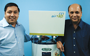
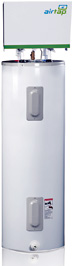
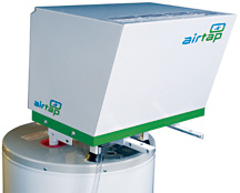
... 
---
[**http://www.airgenerate.com/news/news110908.html**](http://www.airgenerate.com/news/news110908.html)
[**http://www.taunton.com/finehomebuilding/how-to/video/air-tap-water-heater-heating-element.aspx?nterms=72524**](http://www.taunton.com/finehomebuilding/how-to/video/air-tap-water-heater-heating-element.aspx?nterms=72524)
****
---
**
( Video )**
*AirGenerate* is the manufacturer and distributor of
the most energy-efficient water heating system that can
retro-fit onto any existing water heater. The companys
first product, AirTap, converts air energy to heat and
plugs directly into any 30-80 gallon water tank.
This technology results in 250% improved efficiency and
60%-80% energy savings. In addition to these benefits,
AirTap releases cool air which can be ducted using AirVent
(our duct kit) into a household or outside and also acts
as a dehumidifier.
Our customers include home owners, home builders,
business operators, utility companies and government
agencies. We currently sell our products directly on our
website and through our distribution network consisting of
plumbing, HVAC, and eco-product wholesalers and retailers.
We also leverage our partners that include electric
cooperatives and green builders.
The Department of Energy (DOE) considers heat pump water
heaters to be the most functional and cost effective water
heaters. AirGenerate has solved technical and
manufacturing hurdles related to supplying low-cost,
efficient, and quality heat pumps making AirTap the most
competitive water heater.
Our key differentiators are:
\* Technology: Our patent-pending technology does not
require water pumps or electronics making it nearly
maintenance-free.
\* Cost: Smart design and efficient sourcing makes our
units very affordable (<$500).
\* Installation: There is no need for plumbers anymore.
End users can install our units on their own within 1-2
hours. In addition, it has provision for ducting its free
cold air for space cooling in hot seasons and venting out
in winter.
\* Ease of Use: AirTap connects to any existing electric,
gas, or propane water heaters using regular 110V electric
outlet and uses 6 amps to operate.
\* ROI: AirTaps one year payback and 5-year limited
warranty ensures that the hot water system operates for at
least 5 years and gets a high ROI along with energy
savings.
\* Support: We have a training program for plumbers and
offer a dedicated support personnel in case they need
assistance in the field. We also provide team leads for
bigger projects with utilities and co-ops.
\* Multiple Industry Certifications: NTS, GAMA, CSA.
According to GAMA, we are the most energy-efficient water
heater in the country.
On average, Americans spend 14%-25% of their energy
consumption on heating water. Consumers purchase about 10
million water heaters and spend over $10 billion each
year. With the energy prices increasing rapidly, the
green market in the United States, currently at $228
billion, expects an annual growth of over 50%. The global
market and opportunity is exponentially larger.
We raised our first round of funding from family and
friends. We just started shipping our products and expect
to support our existing operations through cash flow.
Our co-founder and CEO, Rick Pal, is an award-winning
serial entrepreneur and investor. Our management team has
over 20 years of combined experience in the field of
energy-efficiency, software, and retail. We plan to use
the award money to fund research on new products and add
personnel to our operations and sales team.
---
**id=22A45CB2ABE14D489CE10C43248ACB16**
**December 15, 2008**
***Indus Business Journal Online***
**AirGenerate taps into
energy-saving industry**
*Connected to water heater, AirTap
maximizes efficiency*
HOUSTON A lot of businesses are talking
green nowadays and looking for ways to capitalize on the
growth industry of energy-efficiency products. Rick Pal
and Sunil Sinha have their entry into the ring with
AirGenerate Inc., but they are also going one more with
their overall goal of making an energy-saving product that
everyone can afford.
The Houston-based AirGenerate has developed
a product, called AirTap, which dramatically improves the
efficiency of standard hot water heaters. AirTap is a
metal, square-shaped device that can be attached to the
top of any 30-80 gallon water tank and then used to heat
water, not with gas or electricity, but through the air
surrounding it. AirTap does this by acting as a
conventional heat pump, using a compressor (powered by a
low-wattage electric current) to extract heat from the
surrounding air, and then sending this heat through long
copper tubes into an adaptor where it is dispersed into
the water tank. This heats the water to the same degree as
would a gas burner or electric heating component.
According to the company, AirTap results in
300 percent improved efficiency and up to 80 percent
energy savings and it has been certified by GAMA under
Department of Energy guidelines as the most energy
efficient water heater in the United States. AirTap uses
about one-fourth of the standard amount of energy to heat
water, by drawing three-fourths of the energy from the
surrounding air. It can reduce energy consumption by
approximately two-and-a-half times that of a standard
water heater or tankless water heater unit.
To put it in perspective, the company offers
the example that AirTap uses less power than an 8-cup
coffee machine to run the compressor, and its energy
consumption level is equivalent to keeping two coffee
machines on for a day.
When faced with the numbers AirTap seems
like a no-brainer and an easy sell. And, as Pal and Sinha
admit, it is. The problem is exposure.
The technology is extremely cool and highly
applicable. The challenge is getting to the consumer,
said Pal, AirGenerates chief executive officer. The
challenge is not selling it. The challenge is getting to
the masses.
Officially launched in January 2008,
AirGenerate took to trade shows after green consumers,
as Pal calls them and also began selling online. Another
strategy was to work with product resellers in the water
and heating industry and to work with plumbers to show
them how to install AirTap.
It is a new product from a new company and
it needed a non-traditional way of selling it as well,
Pal said.
Currently, there are more than 700 AirTap
units installed in 40 states, according to AirGenerate.
The company has six employees in Houston and works with
about 20 contractors.
Recently, it scored some big exposure when
it successfully conducted a heat pump water heater pilot
program with Southern Company.
With nearly 4.4 million customers and more
than 42,000 megawatts of generating capacity,
Atlanta-based Southern Company is the premier energy
company serving the Southeast. It operates four retail
companies -- Alabama Power, Georgia Power, Gulf Power, and
Mississippi Power, serving 120,000 square miles in four
states.
After a successful round of testing in their
labs, Southern Company invited AirGenerate to install
their energy-efficient water heaters in several of their
customers homes. The pilot was conducted over a 2-week
period in October and included customers from Alabama,
Georgia, Florida, and Mississippi. Correct Plumbing of
Houston supervised the installations and worked closely
with several local contractors invited by Southern Company
to watch and learn from the pilot, according to
AirGenerate.
Pal said that such pilot programs are
crucial to AirGenerates success because it generates
believers in the efficiency of AirTap and provides a
growing base of users. The next key strategy is to set up
a distribution network for AirTap in wholesale plumbing
supply stores and at big-box chains, such as Home Depot.
Now we are getting validation and that
makes reps start to believe that there is a demand for
this, Pal said. We have proven there is a market for
it.
Pal and Sinha also believe AirGenerate could
get a boost from a federal tax rebate for using energy
efficient products. AirTap qualifies for this rebate and
its price tag of $499 can be drastically cut into when
consumers get $300 back from the government for using it.
This kind of cost savings, as well as the
energy cost savings consumers can register using AirTap is
exactly what drove Sinha to develop such a product.
He has over 25 years of engineering and
management in the renewable energy, energy conservation
and software development. He has paired academic degrees
in engineering from the Indian Institute of Technology,
Kharagpur, and the University of Hawaii with extensive
research in refrigeration technology, solar thermal
electricity generation, biomass chemical conversion to
useful fuels, methanol fuel cells and integrated renewable
energy systems.
He has worked with organizations such as the
Hawaii Natural Energy Institute, the Gujarat Energy
Development Agency and the Indian Institute of Management
on energy projects looking for alternative energy
products. He also previously developed a self-sustaining
model of energy consumption for a village in India using
local energy resources.
In 2002, he founded Sunlit, a solar
photovoltaic company based out of the San Francisco Bay
Area in California. In 2005, he started a company called
Beyond Pollution, which was the genesis for AirGenerate.
Sinha can lay claim to being the inventor of
AirTap and he says it directly relates to following his
dream of creating commercially-viable, energy-efficient
products.
My desire was coming up with something that
everybody can afford so that everybody can save energy
and save money, he said.
According to Sinha, the need for these types
of products really struck him when a friend asked him to
come up with a solar energy system for his small business.
Sinha said he came up with a system, but it costs
$100,000, which struck him as too expensive and
impractical. Even though the system would work the price
tag made it essentially a failure, in his opinion.
I asked myself, How can I give a solution
to a close friend that is not really appropriate from a
financial point of view? he said.
Taking this experience into the invention of
AirTap, Sinha said it was all about cost and making sure
consumers could get their money back in a year or so. The
feeling was green is coming but unless it is a solution
that is very affordable and people can have it, and afford
it, it is not going to be popular, he added.
Pals and Sinhas paths crossed while each
was working in the Bay Area. Sinha revealed his AirTap
concept to Pal in the fall of 2007, looking for possible
investment, and Pal liked the technology so much, he
convinced Sinha to move to Houston, where Pal resides, to
start AirGenerate only a few months later.
Prior to AirGenerate, Pal was the president
of marketingO, a promotional products company. He also
owned master franchisee rights for Liberty Tax Service in
the Greater Houston Area which he expanded to over 44
offices and 22,000 customers.
A graduate of the University of Texas at
Austin with a business degree, Pal also held several
product management positions at Commerce One, Webify
Solutions, Navis and Iconixx.
He was also a co-founder of iBlitz.com that
was incubated by Garage Ventures and IBM in 2000.
Pal first met Sinha while working at
Commerce One.
Both Pal and Sinha are convinced the time is
now for AirGenerate, in the midst of what they both view
as a green revolution.
There is a lot of interest in this
technology right now and everybody is thinking about
energy savings, Pal said.
It is almost the perfect storm, Sinha
added. It is kind of like being at the right place at the
right time.
---
**USP Appln # 20080000247**
**WO2008005320**
**HEAT PUMP LIQUID HEATER**
2008-01-10
Inventor(s): SINHA SUNIL KUMAR [US]; DEYSARKAR ASOKE
[US]
Applicant(s): BEYOND POLLUTION INC [US]; SINHA SUNIL
KUMAR [US]; DEYSARKAR ASOKE [US]
Classification: - international: F25B27/00;
F25B13/00; F25B27/00; F25B13/00 - European:
F28F9/26; F24H4/04; F25B39/04; F28D7/02D; F28F1/00B;
F28F1/02
Also published as: WO2008005320 //
US2008000247 (A1)
Abstract -- A heat pump liquid heater for
heating a liquid comprising: a heat pump; a liquid tank in
heat communication with the heat pump, wherein the liquid
tank comprises the liquid; and at least one metal
condenser tube immersed into the liquid, wherein the metal
condenser tube forms at least one coil. The metal
condenser tube has a flattened double-tube configuration
and a cross-section defined by concentric ovals such that
at least a portion of the concentric ovals is in contact
with one another thereby minimizing space between the
flattened double-tubes. The heat pump comprises a
tube-in-tube heat exchanger and a compressor, wherein the
tube-in-tube heat exchanger recovers heat from refrigerant
returning from the liquid tank and transfers the recovered
heat to refrigerant going to the compressor thereby
superheating the refrigerant.
Description
FIELD OF THE INVENTION
[0001]The present invention is related to
heat pump liquid heating systems and methods of heating a
liquid.
BACKGROUND OF THE INVENTION
[0002] A Heat Pump Liquid Heater ("HPLH")
uses a refrigeration system to extract heat from the
surrounding environment to heat a liquid. An HPLH system
typically consumes less than half the energy relative to a
conventional, electric-resistance or gas burner liquid
heater. An HPLH system is based on a reverse refrigeration
cycle with the HPLH system using an electrical compressor
to compress the refrigerant to a liquid state which is at
a high pressure and temperature. The refrigerant at high
temperature and pressure transfers heat to a liquid and
then goes though an expansion process where the
temperature and pressure of the refrigerant are reduced to
form a low temperature refrigerant. The low temperature
refrigerant passes through an evaporator absorbing heat
from the surrounding air and converts into a gaseous
state. The gaseous refrigerant is re-compressed in the
compressor and the aforementioned process continues. The
liquid is heated by both the heat transferred from the
ambient air and the electricity used to operate the
compressor making HPLH more than 100% efficient.
[0003] There are basic two types of HPLH
systems described in the references: (i) integrated with a
liquid tank, and (ii) a standalone without a liquid tank.
In both types of systems, the condenser coil is either
immersed into the liquid in the tank where a pump is not
required or the liquid is pumped from the tank to the heat
pump condenser coil. HPLH systems are attached with backup
heating system like electrical elements or gas heaters if
the HPLH system fails, has reduced performance levels, or
if the demand for hot liquid surpasses the capacity of the
HPLH system.
[0004] An HPLH system with a liquid pump
adds to costs, complexity, and maintenance. It also
reduces efficiency because pumps need additional
electrical energy to run. An integrated HPLH system with a
tank is limited to serve only new constructions or to
replace old water heater tanks. There are a few references
of standalone HPLH systems without using liquid pumps
(see, for example, U.S. Pat. Nos. 5,946,927 and
6,233,958). U.S. Pat. No. 5,946,927 discloses a condenser
coil rapped around the water tank on the outside for heat
transfer to the liquid inside the tank. Such a system has
a high cost of manufacturing and reduces the efficiency of
heat transfer from the condenser coil to the liquid
because the condenser coil is not in direct contact with
the liquid.
[0005] U.S. Pat. No. 6,233,958 describes a
standalone heat pump water heater for residential use with
a condenser assembly having a tube-in-tube cylinder
configuration such that an outer cylinder carries a
superheated refrigerant and an inner cylinder returns the
refrigerant to an expansion process. The condenser
assembly is inserted into the water tank though an
existing opening in the top of the tank. As the
refrigerant condenses along the interior surface of the
outer cylinder, the heat from the refrigerant is
transferred to the water. This heat pump water heater has
a limitation of heat transfer to the water because of the
limited surface area provided by the cylindrical condenser
exposed to the water. The limited heat transfer reduces
the efficiency of the system. The diameter of the outer
cylinder should be smaller than the size of the opening in
the tank. The typical size of the opening in residential
water tanks is about 3/4 inches and the height of tank is
typically about 3-5 ft. Therefore, the maximum heat
transfer area is limited by these dimensions. Another
limitation of the heat pump water heater is the reduction
in efficiency due to heating the returning refrigerant by
entering hot refrigerant. The heat gained in the return
refrigerant is wasted. Such a heat pump water heater is
typically suited for a low capacity compressor but will
significantly reduce the efficiency of a typical
residential heat pump water heater.
[0006] Therefore, there is a need for
efficient HPLH systems where liquids such as water can be
heated in a shorter period of time while reducing the
amount of energy used to heat the liquid. Further, there
is a need for HPLH systems that can be easily installed or
easily retrofitted onto preexisting liquid tanks while
providing reduced heating times along with reduced power
consumption. There is also a need for HPLH systems with
increased efficiencies that further provide reduced costs
related to materials and installation of the HPLH systems.
SUMMARY OF THE INVENTION
[0007] In accordance with the foregoing
objectives, provided is a heat pump liquid heater for
heating a liquid comprising: a heat pump; a liquid tank in
heat communication with the heat pump, wherein the liquid
tank comprises the liquid; and at least one metal
condenser tube immersed into the liquid, and wherein the
metal condenser tube forms at least one coil.
[0008] In a second embodiment, a method of
heating a liquid is disclosed. The method of heating the
liquid comprises supplying hot refrigerant from a heat
pump liquid heater via at least one metal condenser tube;
transferring heat from the hot refrigerant to the liquid
in a liquid tank such that the liquid is heated to a
predetermined temperature controlled by a thermostat, and
wherein the metal condenser tube forms at least one coil.
[0009] In a third embodiment, a heat pump
liquid heater for heating a liquid is disclosed. The HPLH
comprises a heat pump; a liquid tank in heat communication
with the heat pump, wherein the liquid tank comprises the
liquid; and at least one metal condenser tube immersed
into the liquid, wherein the metal condenser tube
comprises a refrigerant and is connected to the heat pump,
and wherein the metal condenser tube is immersed into the
liquid via an adaptor assembly, wherein the adaptor
assembly comprises: a metal nipple fixedly attached to an
opening in a liquid tank; a metal union fixedly attached
onto the metal nipple; and a metal tube fixedly attached
to the metal union, wherein the metal tube is adapted to
receive at least one condenser tube and/or a thermostat
bulb.
[0010] In another embodiment, a heat pump
liquid heater for heating a liquid is disclosed. The HPLH
comprises a heat pump; a liquid tank in heat communication
with the heat pump, wherein the liquid tank comprises the
liquid; at least one metal condenser tube immersed into
the liquid, wherein the metal condenser tube comprises a
refrigerant; and a tube-in-tube heat exchanger in fluid
communication with a compressor, wherein the tube-in-tube
heat exchanger recovers heat from refrigerant returning
from the liquid tank and transfers the recovered heat to
refrigerant going to the compressor thereby superheating
the refrigerant.
[0011] In another embodiment, an adaptor
assembly is disclosed. The adaptor assembly comprises a
metal nipple fixedly attached to an opening in a liquid
tank; a metal union fixedly attached onto the metal
nipple; and a metal tube fixedly attached to the metal
union, wherein the metal tube is adapted to receive at
least one condenser tube and/or a thermostat bulb.
[0012] In a most preferred embodiment, the
energy sources of the heat pump liquid heater is solar
energy.
[0013] The following detailed description of
embodiments of the invention, taken in conjunction with
the accompanying drawings, provide a more complete
understanding of the nature and scope of the invention.
BRIEF DESCRIPTION OF THE DRAWINGS
[0014] The above mentioned and other
features and objects of this invention, and the manner of
attaining them, will become more apparent and the
invention itself will be better understood by reference to
the following description of an embodiment of the
invention taken in conjunction with the accompanying
drawings, wherein:
FIG. 1 illustrates a schematic diagram
of an HPLH including an adaptor and a heat pump.
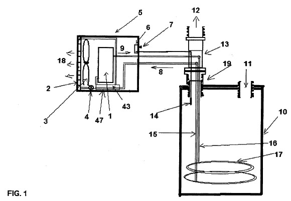
FIG. 2 illustrates an exploded view of
the adaptor schematic shown in FIG. 1.
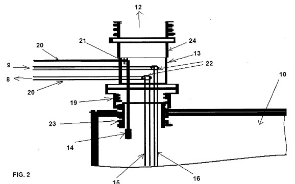
FIG. 3 illustrates a schematic diagram
of metal heating tubes.
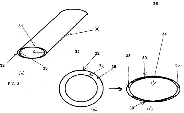
FIG. 4 illustrates an exploded view of
the heat pump schematic shown in FIG. 1.
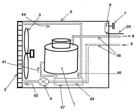
FIG. 5 illustrates a schematic diagram
of an HPLH including a solar power source.
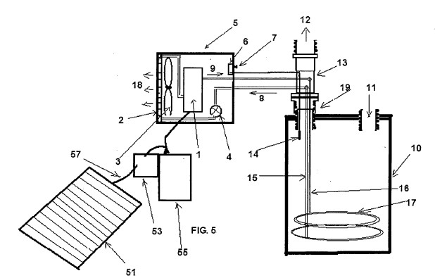
FIG. 6A shows a flowchart of traditional supply of
solar energy to an HPLH and FIG. 6B shows a flowchart of
supplying solar energy to an HPLH according to one
embodiment of the present invention
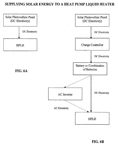
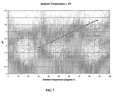
FIG. 7 illustrates a scatter plot of ambient
temperature versus a heat pump water heating system's
energy factor.
[0022] Corresponding reference characters
indicate corresponding parts throughout the several views.
Although the exemplification set out herein illustrates an
embodiment of the invention, the embodiment disclosed
below is not intended to be exhaustive or to be construed
as limiting the scope of the invention to the precise form
disclosed.
DETAILED DESCRIPTION OF THE INVENTION
Definitions
[0023] Unless otherwise stated, the
following terms used in the specification and claims have
the meanings given below:
[0024] Liquid", as used herein, is meant to
include water of all grades and types, oils, fuels, gases,
and mixtures thereof. In preferred embodiments, the liquid
is water, wherein the water can be but is not limited to
tap water, hard water, soft water, mineral water,
dematerialized water, filtered water, steam-distilled
water, salt water, fresh water, distilled water, etc.
[0025] Metal" or "metallic", as used herein,
is meant to include any heat conducting metals and/or
alloys including but not limited to aluminum, copper,
gold, iron, lead, silver, titanium, magnesium, zinc, and
various alloys thereof. The "metal" or "metallic"
components in the present invention are most preferably
copper or alloys of copper.
[0026] Compressor", as used herein, is meant
to include any type of motor driven refrigerant
compression device.
Various Embodiments of the Invention
[0027] The above disadvantages of the prior
art are overcome by the present invention wherein the HPLH
is a standalone system or a retrofitted systems without a
liquid circulating pump and the condenser is a single tube
loop or multiple tube loops immersed in a liquid tank.
[0028] According to a first embodiment of
the present invention, a heat pump liquid heater for
heating a liquid is disclosed. The HPLH comprises a heat
pump; a liquid tank in heat communication with the heat
pump, wherein the liquid tank comprises the liquid; and at
least one metal condenser tube immersed into the liquid,
and wherein the metal condenser tube forms at least one
coil.
[0029] In a preferred embodiment, the metal
condenser tube has a flattened double-tube configuration
and a cross-section defined by concentric ovals such that
at least a portion of the concentric ovals is in contact
with one another thereby minimizing space between the
flattened double-tubes.
[0030] The metal condenser tube is connected
to the heat pump and is immersed into the liquid via an
adaptor assembly. The adaptor assembly is fixedly attached
to the liquid tank. The adaptor assembly connects the heat
pump and the liquid tank.
[0031] The metal condenser tube is a single
continuous coiled tube. The metal condenser tube has a
length of from about 1 ft to about 250 ft, and more
preferably the metal condenser tube has a length of from
about 10 ft to about 100 ft. The metal condenser tube has
a diameter of from about 0.01 inches to about 0.50 inches,
and more preferably the metal condenser tube has a
diameter of about 3/16 inches. The metal condenser tube
has a thickness of about 0.035 inches. The metal condenser
tube is preferably made of copper.
[0032] The metal condenser tube is flexible.
The metal condenser tube has a length and diameter to heat
the liquid to a predetermined temperature in a
predetermined time period. The metal condenser tube has a
surface area to heat the liquid to a predetermined
temperature in a predetermined time period. The metal
condenser tube can have a whisk configuration with
multiple smaller diameter condenser tubes emerging from
the metal condenser tube, wherein the smaller diameter
condenser tubes form coils.
[0033] In another preferred embodiment, the
heat pump comprises a tube-in-tube heat exchanger and a
compressor, wherein the tube-in-tube heat exchanger
recovers heat from refrigerant returning from the liquid
tank and transfers the recovered heat to refrigerant going
to the compressor thereby superheating the refrigerant.
The compressor is powered by a solar energy source and/or
a traditional electric source.
[0034] The HPLH further comprises a
thermostat with a knob, wherein the knob is adjusted by a
user to obtain a predetermined temperature of the liquid.
The liquid in the liquid tank is water.
[0035] According to a second embodiment of
the present invention, a method of heating a liquid is
disclosed. The method of heating the liquid comprises
supplying hot refrigerant from a heat pump liquid heater
via at least one metal condenser tube; transferring heat
from the hot refrigerant to the liquid in a liquid tank
such that the liquid is heated to a predetermined
temperature controlled by a thermostat, and wherein the
metal condenser tube forms at least one coil.
[0036] In a preferred embodiment, the metal
condenser tube has a flattened double-tube configuration
and a cross-section defined by concentric ovals such that
at least a portion of the concentric ovals is contact with
one another thereby minimizing space between the flattened
double-tubes. The heat pump comprises a tube-in-tube heat
exchanger and a compressor, wherein the tube-in-tube heat
exchanger recovers heat from refrigerant returning from
the liquid tank and transfers the recovered heat to
refrigerant going to the compressor thereby superheating
the refrigerant. The compressor is powered by a solar
energy source and/or a traditional electric source. The
heat pump further comprises a thermostat with a knob,
wherein the knob is adjusted by a user to obtain a
predetermined temperature of the liquid.
[0037] The metal condenser tube is a single
continuous coiled tube. The metal condenser tube has a
length of from about 1 ft to about 250 ft, and more
preferably the metal condenser tube has a length of from
about 10 ft to about 100 ft. The metal condenser tube has
a diameter of from about 0.01 inches to about 0.50 inches,
and more preferably the metal condenser tube has a
diameter of about 3/16 inches. The metal condenser tube
has a thickness of about 0.035 inches. The metal condenser
tube is flexible. The metal condenser tube has a length
and diameter to heat the liquid to a predetermined
temperature in a predetermined time period. The metal
condenser tube has a surface area to heat the liquid to a
predetermined temperature in a predetermined time period.
The metal condenser tube has a whisk configuration with
multiple smaller diameter condenser tubes emerging from
the metal condenser tube, wherein the smaller diameter
condenser tubes form coils. The metal tube is preferably
made of copper or an alloy of copper. The refrigerant is
selected from the group consisting of carbon dioxide,
hydrofluorocarbons, and hydrochlorofluorocarbons. The
liquid in the liquid tank is water.
[0038] According to a third embodiment, a
heat pump liquid heater for heating a liquid is disclosed.
The HPLH comprises a heat pump; a liquid tank in heat
communication with the heat pump, wherein the liquid tank
comprises the liquid; and at least one metal condenser
tube immersed into the liquid, wherein the metal condenser
tube comprises a refrigerant and is connected to the heat
pump, and wherein the metal condenser tube is immersed
into the liquid via an adaptor assembly, wherein the
adaptor assembly comprises: a metal nipple fixedly
attached to an opening in a liquid tank; a metal union
fixedly attached onto the metal nipple; and a metal tube
fixedly attached to the metal union, wherein the metal
tube is adapted to receive at least one condenser tube
and/or a thermostat bulb.
[0039] In a preferred embodiment, the metal
condenser tube has a flattened double-tube configuration
and a cross-section defined by concentric ovals such that
at least a portion of the concentric ovals is in contact
with one another thereby minimizing space between the
flattened double-tubes. The adaptor assembly is
retrofitted onto a preexisting liquid tank and/or air
conditioning unit thereby forming a substantially air
tight and water tight connection between the heat pump and
the preexisting liquid tank and/or air conditioning unit.
[0040] The heat pump comprises a
tube-in-tube heat exchanger and a compressor, wherein the
tube-in-tube heat exchanger recovers heat from refrigerant
returning from the liquid tank and transfers the recovered
heat to refrigerant going to the compressor thereby
superheating the refrigerant.
[0041] In another preferred embodiment, the
compressor is powered by a solar energy source and/or a
traditional electric source. The power collected by the
solar photovoltaic panel is DC electricity which is stored
in at least one rechargeable battery via a charge
controller so as to supply DC electricity on demand from
the at least one battery to the heat pump liquid heater.
[0042] In another preferred embodiment, the
power collected by the solar photovoltaic panel is DC
electricity which is stored in at least one rechargeable
battery via a charge controller so as to convert the DC
electricity into AC electricity via an inverter and then
supply the AC electricity on demand to the heat pump
liquid heater. The heat pump further comprises a
thermostat with a knob, wherein the knob is adjusted by a
user to obtain a predetermined temperature of the liquid.
[0043] The metal condenser tube is a single
continuous coiled tube. The metal condenser tube has a
length of from about 1 ft to about 250 ft, and more
preferably the metal condenser tube has a length of from
about 10 ft to about 100 ft. The metal condenser tube has
a diameter of from about 0.01 inches to about 0.50 inches,
and more preferably the metal condenser tube has a
diameter of about 3/16 inches. The metal condenser tube
has a thickness of about 0.035 inches. The metal condenser
tube is preferably made of copper. The metal condenser
tube is flexible. The metal condenser tube has a length
and diameter to heat the liquid to a predetermined
temperature in a predetermined time period. The metal
condenser tube has a surface area to heat the liquid to a
predetermined temperature in a predetermined time period.
The metal condenser tube has a whisk configuration with
multiple smaller diameter condenser tubes emerging from
the metal condenser tube, wherein the smaller diameter
condenser tubes form coils.
[0044] The refrigerant can be any
refrigerant used in traditional air conditioning and/or
heat pump systems. Exemplary refrigerants include carbon
dioxide, hydrofluorocarbons, and hydrochlorofluorocarbons.
Other examples of refrigerants include
chlorodifluoromethane (sold as R-22),
chloropentafluoroethane (sold as R-502),
dichlorodifluoromethane (sold as R-12),
trichlorofluoromethane (sold as R-11),
trichlorotrifluoroethane (sold as R-113),
tetrafluoroethane (sold as R-134a), and
dichlorotrifluoroethane (sold as R-123). In a most
preferred embodiment, the refrigerant is carbon dioxide.
The liquid in the liquid tank is preferably water.
[0045] According to a fourth embodiment of
the present invention, a heat pump liquid heater for
heating a liquid is disclosed. The HPLH comprises a heat
pump; a liquid tank in heat communication with the heat
pump, wherein the liquid tank comprises the liquid; at
least one metal condenser tube immersed into the liquid,
wherein the metal condenser tube comprises a refrigerant;
and a tube-in-tube heat exchanger in fluid communication
with a compressor, wherein the tube-in-tube heat exchanger
recovers heat from refrigerant returning from the liquid
tank and transfers the recovered heat to refrigerant going
to the compressor thereby superheating the refrigerant.
[0046] The heat pump comprises a compressor,
and wherein the tube-in-tube heat exchanger recovers heat
from refrigerant returning from the liquid tank and
transfers the recovered heat to refrigerant going to the
compressor thereby superheating the refrigerant.
[0047] According to a fifth embodiment, an
adaptor assembly is disclosed. The adaptor assembly
comprises a metal nipple fixedly attached to an opening in
a liquid tank; a metal union fixedly attached onto the
metal nipple; and a metal tube fixedly attached to the
metal union, wherein the metal tube is adapted to receive
at least one condenser tube and/or a thermostat bulb.
[0048] The attachment between the metal
nipple and the opening in the liquid tank is substantially
air tight. A commercial small-scale or large-scale air
conditioning unit comprises the liquid tank thereby
forming a retrofitted attachment between the metal nipple
and the opening in the liquid tank.
[0049] Turning now to the drawings, FIG. 1
illustrates a schematic diagram of a heat pump water
heating system according to one embodiment of the
invention. The heat pump water heating system includes a
heat pump 5 having a compressor 1, an evaporator 2 with a
fan 3, an expansion device 4, a thermostat controller 6,
and a thermostat knob 7.
[0050] Compressed refrigerant 9 exits the
compressor 1 at a temperature controlled via the
thermostat controller 6 when a user adjusts a thermostat
knob 7. The compressed refrigerant 9 exits the compressor
1 at a high pressure and a high enthalpy. The refrigerant
then flows into the liquid tank 10 at a high pressure via
a single coiled condenser tube 16. A liquid such as water
11 flows into the liquid tank 10 and exchanges heat with
the compressed refrigerant 9 flowing through the single
coiled condenser tube 16, which is immersed into the
liquid in the liquid tank 10. In the liquid tank 10, the
compressed refrigerant 9 transfers heat into the liquid,
and the refrigerant exits the liquid tank 10 via the
returning single coiled condenser tube 15 as cooled
refrigerant 8. The cooled refrigerant 8 is at a low
enthalpy and a high pressure. The coiled condenser tubes
15 and 16 form a coiled bundle 17 which remains immersed
in the liquid.
[0051] The cold liquid 11 enters the liquid
tank 10 and gets heated by superheated refrigerant in the
coiled condenser tube generally defined by 15, 16 and 17
in FIG. 1. Hot water 12 exits the liquid tank 10 via an
adaptor assembly 13 fixedly attached to the opening in the
liquid tank 10 by a union 19 (see FIG. 2 for more
description on the adaptor assembly 13). Most of the heat
transfer from the single coiled condenser tube occurs
towards the bottom of the liquid tank 10 wherein cold
liquid tends to settle towards the bottom as heated liquid
tends to rise towards the top of the liquid tank 10
providing a more homogenized liquid temperature in the
liquid tank 10 compared to similar conventional HPLH
systems. This homogenizing process enhances the heating
efficiency of the HPLH.
[0052] The refrigerant 8 has higher
temperature than liquid in the tank and its heat can be
recovered before it passes though the expansion process in
4 for better efficiency. The refrigerant 8 passes though a
tube-in-tube heat exchanger (also referred to as the
economizer) 47 (shown in FIG. 4) where the heat from the
returning refrigerant 8 is transferred to the refrigerant
43 (shown in FIG. 4) and passed to the compressor.
[0053] FIG. 2 illustrates an exploded view
of the adaptor assembly 13 shown in FIG. 1. The adaptor
assembly 13 is a pipe fitting which connects the heat pump
5 and the liquid tank 10. The adaptor assembly 13 also
facilitates flow of liquid 12 exiting the liquid tank 10.
The adaptor assembly 13 also facilitates refrigerant flow
via the coiled condenser tubes 15 and 16. Moreover, the
adaptor assembly 13 facilitates the attachment of a
thermostat immersion bulb 14 (also shown in FIG. 1) such
that the bulb can be immersed into the liquid in the
liquid tank 10 for accurate and efficient monitoring of
the liquid temperature.
[0054] The adaptor assembly 13 is fixedly
attached by thread fitting a metal nipple 23 to a threaded
hole in the liquid tank 10. A metal union 19 is thread
fitted on the nipple 23. A metal tube 13 is either thread
fitted or compression fitted to the union 19 depending on
the type of union. The metal tube 13 has two holes 22
through which the coiled condenser tubes 15 and 16 can
pass. An air tight weld is formed at the two holes 22
making the adaptor assembly substantially air tight. A
tube 13 has an open notch 21 at one end.
[0055] The thermocouple capillary tube 20
having the thermostat bulb 14 is inserted through the
notch 21. As the thermostat bulb 14 is usually
substantially large and cannot bend, the notch 21 aids in
the insertion of the thermostat bulb into the liquid tank
10. A metal pipe fitting with female solder sup and male
thread 24 is connected to the tube 13. The cup of fitting
24 is welded to the tube 13 in such a way that the notch
21 is sealed. The adaptor assembly 13 enhances the
efficiency of the HPLH system by accommodating the coiled
condenser tubes and the thermostat bulb 14. Moreover, the
adaptor assembly 13 including the coiled condenser tubes
15, 16, and 17 and the thermostat bulb 14 can be inserted
into the threaded hole in the liquid tank without
requiring to move the heat pump 5.
[0056] In another embodiment, the thermostat
can be a non-immersion type thermostat which is externally
mounted on a wall of the liquid tank 10 as in the case of
conventional electrical water heater tanks.
[0057] The coiled condenser tubes 15, 16 and
17 can be made of any metal. In another embodiment, the
coiled condenser tubes 15, 16, and 17 can be made of
copper or an alloy of copper. The coiled condenser tubes
can be made from a single tube forming coils or multiple
tubes forming coils. The coiled condenser tubes can each
be made of a single wall tube or double walls in order to
prevent any contamination of the liquid in the liquid tank
10 with refrigerant due to a rupture in a single tube
configuration.
[0058] FIG. 3 illustrates a schematic
diagram of coiled condenser tubes 15, 16 and 17 for double
wall configuration. Double wall condenser tube 15, 16 and
17 may be required for some building code. In a preferred
embodiment, the metal tubes 15 and 16 are made of
concentric metal tubes so as avoid the contamination of
the liquid with the refrigerant. A cross-section of the
concentric metal tubes is shown in FIG. 3(a). FIG. 3(a)
shows the cross-section of concentric metal tubes, wherein
an outer tube 32 envelopes an inner tube 33. A gap 35 is
formed between the outer tube 32 and the inner tube 33
such that air is trapped in the gap 35. The air trapped in
the gap 35 conducts heat from the inner tube 33 to the
outer tube 32. Due to the presence of air in the gap 35 as
an intermediary for heat conduction between the inner tube
33 and the outer tube 32, some heat is lost in heating the
air in the gap. Further, air is not as good of a conductor
of heat as the metal tubes therefore the efficiency of
heating the liquid is decreased.
[0059] In a more preferred embodiment, the
metal tubes 15 and 16 are each made of concentric metal
tubes, wherein the concentric metal tubes are shown in
FIGS. 3(b)1 and (b)2. FIG. 3(b)1 shows a flattened tube
and FIG. 3(b)2 shows a cross-section of the flattened tube
shown in FIG. 3(b)1. The cross-section shown in FIG. 3(a)
shows two concentric circles wherein the gap between the
two concentric circles is substantially the same
throughout the circumference of the two concentric
circles. However, the cross-section shown in FIG. 3(b)2
shows two concentric ovals wherein the gap between the two
concentric ovals is such that the gap between the two
ovals is substantially minimized while still providing a
double tube configuration. The oval double-tube
configuration exemplified in FIG. 3(b)2 not only provides
protection against contamination of the liquid with any
leaked refrigerant but also conducts heat more efficiently
than the double tube configuration shown in FIG. 3(a) as
the amount of air in the gap between the concentric tubes
in FIGS. 3(b)1 and 3(b)2 is minimized.
[0060] The condenser of the HPLH is attached
to the liquid tank using an adaptor assembly of the
present invention. The adaptor assembly fits into a
preexisting hole in the tank cover preferably on a hot
liquid outlet. The adaptor assembly can also be fitted
onto a hole on a side wall or any other opening on the
liquid tank. The bottom of the adaptor assembly is screwed
into the hole in the liquid tank and the top of the
adaptor assembly is fixedly attached to the hot liquid
outlet pipe.
[0061] As mentioned above, the condenser is
a single continuous tube or multiple loops with a sharp
bend at the middle making a loop. The surface area of the
condenser tube, which is determined by the length and the
diameter of the condenser tube, can be designed to heat
the liquid in the liquid tank to a predetermined
temperature in a predetermined time period. The two ends
of the looped condenser tube along with an immersion
thermocouple tube pass through the adaptor assembly and
protrude out of the adaptor wall.
[0062] Moreover, condenser tube length can
be designed to be of any predetermined length depending on
the capacity of the compressor. The larger the compressor
capacity the longer the length of the condenser tube will
be in order to maximize heat transfer from superheated
refrigerant to the liquid in the liquid tank. The diameter
of the condenser tube is designed to have enough
flexibility so that it can be inserted into tank easily.
The metal condenser tube has a length and diameter and
wall thickness of any dimension. The metal condenser tube
has a length and diameter to heat the liquid to a
predetermined temperature in a predetermined time period.
The metal condenser tube has a surface area to heat the
liquid to a predetermined temperature in a predetermined
time period.
[0063] The condenser tube curls towards the
bottom of the liquid tank wherein as liquid at a lower
temperature is heated to form hot liquid, the hot liquid
rises towards the top of the liquid tank. This process
aids in homogenizing the liquid temperature in the liquid
tank and improves efficiency of the HPLH.
[0064] The condenser tube is coiled so as to
form a bundle. The primary purpose of bundling the
condenser tube is to aid in easy removal of the condensing
tube from the liquid tank and thereby aiding in easy
disconnection of the heat pump from the liquid tank. The
condenser tube bundle can be tied together at the top for
ease in pulling out from the hole of the tank cover. The
bundle is scattered towards the bottom of the liquid tank
for improved heat transfer by exposing the condenser to a
large surface area of the liquid in the liquid tank.
[0065] A traditional short length straight
or un-coiled condenser tube is difficult to insert into
the liquid tank through a hole while holding the HPLH. In
contrast, the long bundle of the condenser tubes of the
present invention are easy to insert into the liquid tank
through a hole in the liquid tank as the HPLH can be
placed on any convenient surface while inserting the
bundled condenser tube into the liquid tank. Once the
bundled condenser tube is inserted into the liquid tank,
the HPLH can be placed in any desired position such as on
the top of the liquid tank.
[0066] FIG. 4 illustrates an exploded view
of the heat pump 5 shown in FIG. 1. The returning
refrigerant 8 is carried out from a liquid tank 10 to the
expansion device 4. The returning refrigerant 8 passes
through the expansion device 4 after it exits the
tube-in-tube heat exchanger 47. The expansion device 4
expands and reduces the pressure of the refrigerant. The
expansion device 4 can be capillary tube or Automatic
Expansion Valve ("AEV") or Thermostatic Expansion Valve
("TEV") or Electric or Electronic Expansion Valves ("EXV")
or other known type of expansion device.
[0067] After expansion, the refrigerant
flows into the evaporator 2 equipped with a fan 3 and
exits at a high enthalpy and a low pressure. In the
evaporator 2, the refrigerant absorbs heat from
surrounding air thereby heating the refrigerant. The flow
of the surrounding air is aided by the fan 3 such that the
surrounding air exchanges heat with the refrigerant
passing through the evaporator 2. The temperature
difference between the surrounding air and the refrigerant
in the evaporator 2 drives the thermal energy transfer
from the surrounding air to the refrigerant as the
refrigerant flows through the evaporator 2. The fan 3
moves the surrounding air across the evaporator 2,
maintaining the temperature difference and evaporating the
refrigerant. The refrigerant 44 and 45 goes through extra
superheating in tube-in-tube heat exchanger 47 then
reenters the compressor 1, completing the cycle.
[0068] The heating capacity of a compressor
1 is defined as the capacity of the compressor 1 to heat
the liquid 11 in the liquid tank 10. The heat pump 5 can
include an auxiliary electric heater in another embodiment
that can further heat the liquid 12 exiting the liquid
tank 10 to increase the heating capacity of the heat pump
5. The auxiliary electric heater can be located anywhere
on the liquid line exiting the liquid tank 10. The
auxiliary heating element can also be the existing one
with the typical electrical liquid tank or new one may be
attached anywhere in the body of the tank. The auxiliary
electric heater can be activated to further heat the
liquid 12 exiting the liquid tank 10 when the heating
capacity of the heat pump 5 does not meet demand. The
auxiliary electric heater can also be activated using
cold-temperature thermostat for freezing cold air
conditions or activated when there is excess demand of hot
liquid.
[0069] Further to the description of the
heat pump 5 with respect to FIG. 1, a heat recovery heat
exchanger 47 (also referred to as an economizer) adds to
increasing the efficiency of the HPLH of the present
invention. The reason for this is that most of the latent
heat in returning refrigerant 8 is normally lost in the
expansion process, however, according to one embodiment of
the present invention, a substantial portion of the latent
heat in the returning refrigerant 8 is recovered and
transferred to refrigerant 41 as "superheat". The recovery
and use of this additional heat increases the efficiency
of the HPLH of the present invention. The heat exchanger
47 can be a tube-in-tube heat exchanger and can be
substituted with any other heat exchanger in the system.
[0070] In the evaporator 2, the refrigerant
absorbs heat from surrounding air thereby heating the
refrigerant. The flow of the surrounding air is aided by
the fan 3 such that the surrounding air exchanges heat
with the refrigerant passing through the evaporator 2 in a
known manner. The temperature difference between the
surrounding air and the refrigerant in the evaporator 2
drives the thermal energy transfer from the surrounding
air to the refrigerant as the refrigerant flows through
the evaporator 2. The fan 3 moves the surrounding air
across the evaporator 2, maintaining the temperature
difference and evaporating the refrigerant. Refrigerant 44
extracts heat from air in the evaporator 2 and then
reenters the compressor 1 by first passing through the
heat exchanger 43 for superheating the refrigerant to a
superheated refrigerant 45.
[0071] FIG. 5 illustrates a preferred
embodiment of the present invention and shows a schematic
diagram of a heat pump water heating system including a
solar power source. The various components and functions
have been described herein above with respect to FIG. 1,
except FIG. 5 electrical energy input is from solar energy
rather than a traditional electric source. Solar energy is
inputted to the compressor 1 from a storage battery 55
that stores solar energy. A solar photovoltaic panel 51
collects solar energy this collected solar energy is
transferred to a solar charge controller 53 for the
storage battery 55 via a connecting wire 57. HPLH system
can run directly from batteries or thought an alternating
current inverter depending on the electrical requirement
of the components of HPLH.
[0072] Solar energy can be used to power the
auxiliary electric heater, the economizer, and/or any
other component requiring electricity. The conversion of
solar energy to thermal or electrical energy through the
use of systems such as photovoltaic arrays, passive
absorbers of solar energy, solar furnaces, trough
concentrating collectors with sun trackers is well
established in the art. U.S. Pat. No. 4,315,163 describes
a multipower electrical system for supplying electrical
energy to a house including a solar photovoltaic array, a
battery charger and DC to AC inverter. U.S. Pat. No.
4,147,157 describes an active solar energy system
comprising an array of solar collectors for both
generating power for a pump and for heating a liquid, a
pumping device powered by the array to circulate the
heated liquid and a storage tank to contain the heated
liquid. Similarly, U.S. Pat. No. 5,293,447 describes a
system for heating water using solar energy comprising a
photovoltaic array, a water heater and a controller.
Systems have also been proposed for simultaneously
converting solar energy to thermal and electrical. For
example, U.S. Pat. No. 4,392,008 describes a flat plated
solar thermal collector below and in spaced conductive
relationship to a plate-mounted array of photovoltaic
cells. U.S. Pat. No. 5,522,944 describes an apparatus with
an array of photovoltaic cells and a plurality of
interconnected heat collecting tubes disposed on the same
plane with the array.
[0073] FIG. 6A shows a flowchart of how
solar energy is traditionally supplied to an HPLH. First,
a solar photovoltaic panel collects solar energy in the
form of DC electricity. This DC electricity is then
directly supplied to an HPLH. FIG. 6B shows a flowchart of
supplying solar energy to an HPLH according to one
embodiment of the present invention. Solar energy is
collected by a solar photovoltaic panel in the form of DC
electricity. The DC electricity is stored in an
electricity storage device such as a rechargeable battery
or a combination of such batteries using a charge
controller. The DC electricity stored in the battery or
combination of batteries can then be supplied on demand
directly to an HPLH or can first be converted into AC
electricity using an inverter before being supplied on
demand to the HPLH. The use of a battery or a combination
of batteries to store collected solar energy enables the
HPLH to have a substantially consistent availability of
electricity to power the HPLH. Moreover, when the HPLH is
not in use the battery or combination of batteries can
store the collected power until the HPLH is in use again.
Similarly, stored solar energy enables the HPLH to be used
substantially consistently during heavy use.
[0074] Further, the heating efficiency of
the HPLH is improved by recovering heat from the returning
refrigerant from the condenser. The returning refrigerant
from the condenser has equal or higher temperature than
the liquid in the liquid tank. The heat in the returning
refrigerant is traditionally lost during an expansion
process. However, the HPLH of the present invention
recovers this heat by the heat exchanger (i.e.,
economizer) or by using any other type of heat exchanger,
wherein heat from the returning refrigerant is transferred
to the refrigerant going into the compressor.
[0075] Moreover, according to one
embodiment, a retrofitting method is disclosed. In the
retrofitting method the HPLH of the present invention can
be used with a portable air conditioning (heating or
cooling) unit available in the market. Such retrofitting
can be achieved by first either removing the evaporator
coil or condenser coil from the air conditioning unit and
the remaining coil can be used as the evaporator of the
HPLH. Second, the bundled condenser tube is attached at
one end to the high pressure opening of the compressor and
the other end of the condenser tube is attached to the
existing expansion device of the system such that the
middle portion of the condenser tube is inserted into the
liquid tank and is immersed into the liquid. Third, the
expansion device can be attached on the other end to an
evaporator with an existing fan. Fourth, the other end of
the evaporator can be attached to a low pressure end of a
compressor making the system a closed cycle. Optionally,
as a fifth step, the cold temperature thermostat switch
can be removed and instead a high temperature thermostat
switch can be added to the circuit for complete on/off
switch capability of the system. The thermostat can be an
immersion type or a traditional thermostat attached to the
outside wall of the tank. An air filter can be attached on
air inlet vents of the retrofitted HPLH.
[0076] In another embodiment, the HPLH of
the present invention can be used for retrofitting onto
commercial air conditioning units. The condenser unit with
compressor, expansion device and fan is used as evaporator
in commercial HPLH. The tube connections are changed so
that one end of condenser tube is connected to the high
pressure opening of the compressor. Condenser tube is
inserted through the opening of the liquid tank and is
immersed in liquid. The other end of the condenser is
attached to the existing expansion device of the system.
The expansion device is attached to one end of evaporator
with the existing fan. The other end of the evaporator is
attached to the low pressure end of compressor making the
system a closed cycle. The cold temperature thermostat
switch is removed and instead a high temperature
thermostat switch is added to the circuit for complete
on/off of the system. The thermostat is preferably
immersion type. An air filter can be attached on air inlet
vents of the system.
[0077] Although air surrounding the HPLH
generally contains enough heat to allow efficient
operation of the HPLH, there can be occasions when the wet
bulb air temperature approaches freezing, in which case
frost begins to form on the evaporator. In such an event
the HPLH can become inefficient. In one embodiment, an
electric heater can be used to heat the air going through
the evaporator causing defrosting which substantially
removes any blockage caused by the frost. In another
embodiment, the evaporator can be heated directly by an
electric heater to defrost the evaporator and thereby
substantially remove any blockage caused by the frost. In
another embodiment, a low temperature thermostat can be
added to the evaporator of the HPLH so that the thermostat
can sense the formation of frost on the evaporator and a
control means can be automatically activated when the
frost is sensed so as to defrost the evaporator by
switching on the electric heater. Similarly, the control
means can turn the heater off when the defrosting is
completed as sensed by the thermostat. See, for example,
U.S. Pat. No. 4,517,807 for further information regarding
defrosting an evaporator using a thermostat and a control
means.
[0078] Further, the HPLH improves heating
efficiency, saves space, reduces system and installation
costs, removes need of liquid circulating pump and its
controllers, reduces the maintainable parts in the system
and is easy to install. The HPLH can be added to an
existing liquid tank or can be integrated with a new
liquid tank. Furthermore, altering the length of the
condenser aids in tailoring the use of the HPLH for
smaller-scale residential use as well as for larger-scale
commercial use.
[0079] All the above embodiments of HPLH are
further enhanced to use adaptors to channel inlet air flow
and outlet cool air flow to desired space for air
conditioning.
[0080] All the above embodiment of HPLH
includes a drain hole and tube attachment for the removal
of condensate from the evaporator.
[0081] Performance data of the heat pump
system shown in FIG. 1 for heating water using traditional
electricity to power the system is provided herein below
in Table 1:
TABLE-US-00001 Ambient Temperature (.degree.
F.) Energy Factor ("EF") 30 1.86 32 1.93 68 3.00 69 3.13
71 3.35 78 3.47 80 3.67 83 3.67 88 3.80

[0082] The refrigerant is R22. The Energy
Factor ("EF") in the above table is defined as the ratio
of heat output to energy input divided by conventional
electrical liquid heater efficiency factor. Conventional
electric resistance water heater efficiency factor is
0.86. A scatter plot of the above data is shown in FIG. 7
with a trendline. The higher the EF, the more efficient
the water heater, and therefore FIG. 7 shows that the
efficiency of the water heater increases as the ambient
temperature of the water increases.
[0083] While the invention has been
described with reference to a preferred embodiment, it
will be understood by those skilled in the art that
various changes may be made and equivalents may be
substituted for elements thereof without departing from
the scope of the invention. In addition, many
modifications may be made to adapt a particular situation
or material to the teachings of the invention without
departing from the essential scope thereof. Therefore, it
is intended that the invention not be limited to the
particular embodiment disclosed as the best mode
contemplated for carrying out this invention, but that the
invention will include all embodiments falling within the
scope of the appended claims.
[0084] All of the above-mentioned references
are herein incorporated by reference in their entirety to
the same extent as if each individual reference was
specifically and individually indicated to be incorporated
herein by reference in its entirety.
---
---