Yi CUI, et al Electrified NanoSilver Water Purification
**
[rexre](../index.htm)**[**search.com**](../index.htm)
---
**Yi CUI*, et al***
**Electrified NanoSilver** **Water Purification**
---
***Electrified silver nanowires / carbon
nanotubes / cotton kills most bacteria within seconds***
---
---
**[L. Bergeron11 :
High-speed filter uses electrified nanostructures to purify
water at low cost](#bergeron)
[David T. Schoen, et al. : High Speed Water
Sterilization Using One-Dimensional Nanostructures](#schoen)
[WO201113393 : Water Sterilization Devices](#pat-wo)
[Nano-Silver Manufacture Patents](#nano-ag)**
---
[**http://phys.org/news202464996.html**](http://phys.org/news202464996.html)**Aug 31, 2010**
**High-speed filter uses electrified
nanostructures to purify water at low cost**
**By Louis Bergeron**
By dipping plain cotton cloth in a high-tech broth full of silver
nanowires and carbon nanotubes, Stanford researchers have
developed a new high-speed, low-cost filter that could easily be
implemented to purify water in the developing world.
Instead of physically trapping bacteria as most existing filters
do, the new filter lets them flow on through with the water. But
by the time the pathogens have passed through, they have also
passed on, because the device kills them with an electrical field
that runs through the highly conductive "nano-coated" cotton.
In lab tests, over 98 percent of Escherichia coli bacteria that
were exposed to 20 volts of electricity in the filter for several
seconds were killed. Multiple layers of fabric were used to make
the filter 2.5 inches thick.
"This really provides a new water treatment method to kill
pathogens," said Yi Cui, an associate professor of materials
science and engineering. "It can easily be used in remote areas
where people don't have access to chemical treatments such as
chlorine."
Cholera, typhoid and hepatitis are among the waterborne diseases
that are a continuing problem in the developing world. Cui said
the new filter could be used in water purification systems from
cities to small villages.
**Faster filtering by letting bacteria through**
Filters that physically trap bacteria must have pore spaces small
enough to keep the pathogens from slipping through, but that
restricts the filters' flow rate.
Since the new filter doesn't trap bacteria, it can have much
larger pores, allowing water to speed through at a more rapid
rate.
"Our filter is about 80,000 times faster than filters that trap
bacteria," Cui said. He is the senior author of a paper describing
the research that will be published in an upcoming issue of Nano
Letters. The paper is available online now.
The larger pore spaces in Cui's filter also keep it from getting
clogged, which is a problem with filters that physically pull
bacteria out of the water.
Cui's research group teamed with that of Sarah Heilshorn, an
assistant professor of materials science and engineering, whose
group brought its bioengineering expertise to bear on designing
the filters.
Silver has long been known to have chemical properties that kill
bacteria. "In the days before pasteurization and refrigeration,
people would sometimes drop silver dollars into milk bottles to
combat bacteria, or even swallow it," Heilshorn said.
Cui's group knew from previous projects that carbon nanotubes were
good electrical conductors, so the researchers reasoned the two
materials in concert would be effective against bacteria. "This
approach really takes silver out of the folk remedy realm and into
a high-tech setting, where it is much more effective," Heilshorn
said.
**Using the commonplace keeps costs down**
But the scientists also wanted to design the filters to be as
inexpensive as possible. The amount of silver used for the
nanowires was so small the cost was negligible, Cui said. Still,
they needed a foundation material that was "cheap, widely
available and chemically and mechanically robust." So they went
with ordinary woven cotton fabric.
"We got it at Wal-mart," Cui said.
To turn their discount store cotton into a filter, they dipped it
into a solution of carbon nanotubes, let it dry, then dipped it
into the silver nanowire solution. They also tried mixing both
nanomaterials together and doing a single dunk, which also worked.
They let the cotton soak for at least a few minutes, sometimes up
to 20, but that was all it took.
The big advantage of the nanomaterials is that their small size
makes it easier for them to stick to the cotton, Cui said. The
nanowires range from 40 to 100 billionths of a meter in diameter
and up to 10 millionths of a meter in length. The nanotubes were
only a few millionths of a meter long and as narrow as a single
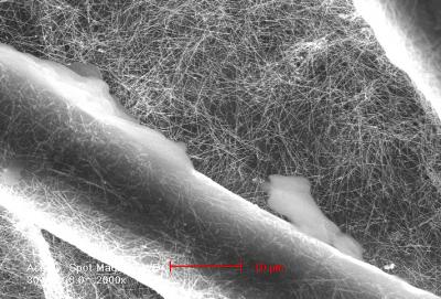
billionth of a meter. Because the nanomaterials stick so well, the
nanotubes create a smooth, continuous surface on the cotton
fibers. The longer nanowires generally have one end attached with
the nanotubes and the other end branching off, poking into the
void space between cotton fibers.
"With a continuous structure along the length, you can move the
electrons very efficiently and really make the filter very
conducting," he said. "That means the filter requires less
voltage."
**Minimal electricity required**
The electrical current that helps do the killing is only a few
milliamperes strong - barely enough to cause a tingling sensation
in a person and easily supplied by a small solar panel or a couple
12-volt car batteries. The electrical current can also be
generated from a stationary bicycle or by a hand-cranked device.
The low electricity requirement of the new filter is another
advantage over those that physically filter bacteria, which use
electric pumps to force water through their tiny pores. Those
pumps take a lot of electricity to operate, Cui said.
In some of the lab tests of the nano-filter, the electricity
needed to run current through the filter was only a fifth of what
a filtration pump would have needed to filter a comparable amount
of water.
The pores in the nano-filter are large enough that no pumping is
needed - the force of gravity is enough to send the water speeding
through.
Although the new filter is designed to let bacteria pass through,
an added advantage of using the silver nanowire is that if any
bacteria were to linger, the silver would likely kill it. This
avoids biofouling, in which bacteria form a film on a filter.
Biofouling is a common problem in filters that use small pores to
filter out bacteria.
Cui said the electricity passing through the conducting filter may
also be altering the pH of the water near the filter surface,
which could add to its lethality toward the bacteria.
Cui said the next steps in the research are to try the filter on
different types of bacteria and to run tests using several
successive filters.
"With one filter, we can kill 98 percent of the bacteria," Cui
said. "For drinking water, you don't want any live bacteria in the
water, so we will have to use multiple filter stages."
Cui's research group has gained attention recently for using
nanomaterials to build batteries from paper and cloth.
---
---
**pubs.acs.org/doi/full/10.1021/nl101944e****Nano Lett., 2010, 10 (9), pp 3628a3632****DOI: 10.1021/nl101944e**
**High Speed Water Sterilization Using
One-Dimensional Nanostructures**
**David T. Schoen a , Alia P. Schoen a , Liangbing Hu , Han Sun
Kim , Sarah C. Heilshorn and Yi Cui \***
**Department of Materials Science and Engineering, Stanford
University, Stanford, California 94305**
The removal of bacteria and other organisms from water is an
extremely important process, not only for drinking and sanitation
but also industrially as biofouling is a commonplace and serious
problem. We here present a textile based multiscale device for the
high speed electrical sterilization of water using silver
nanowires, carbon nanotubes, and cotton. This approach, which
combines several materials spanning three very different length
scales with simple dying based fabrication, makes a gravity fed
device operating at 100000 L/(h m2) which can inactivate >98%
of bacteria with only several seconds of total incubation time.
This excellent performance is enabled by the use of an electrical
mechanism rather than size exclusion, while the very high surface
area of the device coupled with large electric field
concentrations near the silver nanowire tips allows for effective
bacterial inactivation.
---
**US2011259747****WO2011133932**
**WATER STERILIZATION DEVICES INCLUDING NANOSTRUCTURES AND USES
THEREOF**
**Abstract**
A water sterilization device includes: (1) a conduit including an
inlet to provide entry of untreated water and an outlet to provide
exit of treated water; (2) a porous electrode housed in the
conduit and disposed between the inlet and the outlet, the porous
electrode including a porous support and nanostructures coupled to
the porous support; and (3) an electrical source coupled to the
porous electrode.
**Description**
**FIELD OF THE INVENTION**
[0002] The invention relates generally to sterilization of fluids.
More particularly, the invention relates to water sterilization
devices including nanostructures and uses thereof.
**BACKGROUND**
[0003] The removal of bacteria and other harmful organisms from
water is an important process, not only for drinking and
sanitation but also industrially as biofouling is a commonplace
and serious problem. Conventional approaches for water
sterilization include chlorination and membrane-based approaches.
Unfortunately, both of these types of approaches suffer from
certain deficiencies.
[0004] Chlorination is typically a slow process, involving
incubation times up to an hour or more to allow CP ions to
adequately dissipate through water to be treated. Also,
chlorination can yield hazardous oxidation byproducts, including
carcinogenic species, and chlorination equipment can be capital
intensive, both from the standpoint of deployment and maintenance.
[0005] Conventional membrane-based approaches typically operate
based on size exclusion of bacteria, which can involve a high
pressure drop across a membrane and clogging of the membrane.
Moreover, conventional membrane-based approaches can be energy
intensive, and can suffer from low flow rates across a membrane.
[0006] It is against this background that a need arose to develop
the water sterilization devices and related methods and systems
described herein.
**SUMMARY**
[0007] One aspect of the invention relates to a water
sterilization device. In one embodiment, the device includes: (1 )
a conduit including an inlet to provide entry of untreated water
and an outlet to provide exit of treated water; (2) a porous
electrode housed in the conduit and disposed between the inlet and
the outlet, the porous electrode including a porous support and
nanostructures coupled to the porous support; and (3) an
electrical source coupled to the porous electrode.
[0008] Another aspect of the invention relates to a method of
sterilization. In one embodiment, the method includes: (1)
providing a fibrous material and nanostructures coupled to the
fibrous material,, at least one of the nanostructures including a
metal and having an aspect ratio that is at least 5; and (2)
passing a fluid stream through the fibrous material, so as to at
least partially sterilize the fluid stream based on exposure to
the nanostructures.
[0009] Other aspects and embodiments of the invention are also
contemplated. The foregoing summary and the following detailed
description are not meant to restrict the invention to any
particular embodiment but are merely meant to describe some
embodiments of the invention.
**BRIEF DESCRIPTION OF THE DRAWINGS**
[0010] For a better understanding of the nature and objects of
some embodiments of the invention, reference should be made to the
following detailed description taken in conjunction with the
accompanying drawings.
**[0011] FIG. 1 illustrates a water sterilization device
implemented in accordance with an embodiment of the invention.****[0012] FIG. 2 is a magnified view of a porous structure
implemented in accordance with an embodiment of the invention.****[0013] FIG. 3 illustrates a water filtration system
implemented in accordance with an embodiment of the invention.****[0014] FIG. 4 illustrates a water sterilization device
implemented in accordance with another embodiment of the
invention.****[0015] FIG. 5 illustrates a water sterilization device
implemented in accordance with yet another embodiment of the
invention.****[0016] FIG. 6 illustrates a gravity-fed, porous structure
implemented in accordance with an embodiment of the invention.****[0017] FIG. 7 illustrates the performance of a porous
structure as a function of applied voltage, according to an
embodiment of the invention.** **[0018] FIG. 8(A) illustrates the performance of a porous
structure over time, according to an embodiment of the
invention.****[0019] FIG. 8(B) illustrates the performance of a porous
structure as a function of bacterial density, according to an
embodiment of the invention.****[0020] FIG. 9 illustrates inactivation efficacy for
different filtration path lengths and different porous
structures, according to an embodiment of the invention.****[0021 ] FIG. 10 compares inactivation efficacy of porous
structures with silver nanowires relative to porous structures
without silver nanowires, according to an embodiment of the
invention.****[0022] FIG. 1 1 (A) and FIG. 1 1 B illustrate finite
element simulations of electric field intensity in the vicinity
of a nanowire, according to an embodiment of the invention.** **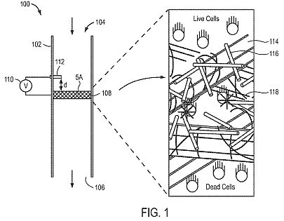 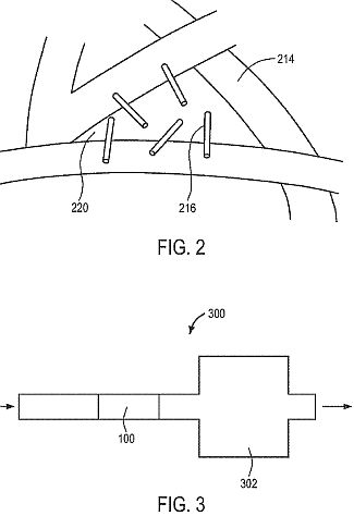 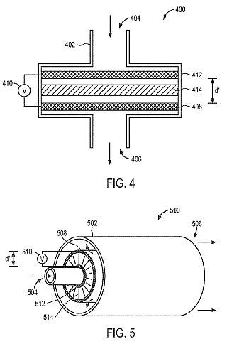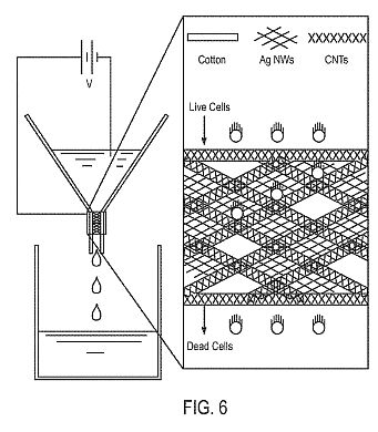 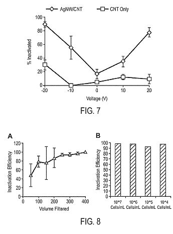 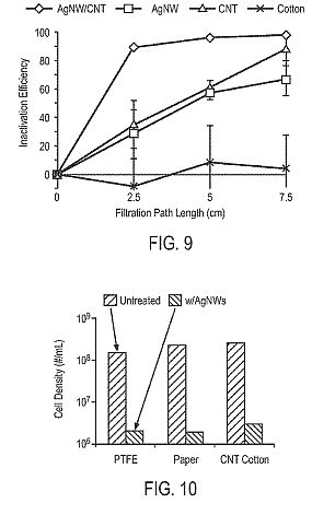 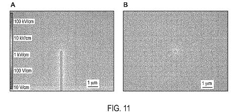****DETAILED DESCRIPTION****Definitions**
[0023] The following definitions apply to some of the aspects
described with respect to some embodiments of the invention. These
definitions may likewise be expanded upon herein.
[0024] As used herein, the singular terms "a," "an," and "the"
include plural referents unless the context clearly dictates
otherwise. Thus, for example, reference to an object can include
multiple objects unless the context clearly dictates otherwise.
[0025] As used herein, the term "set" refers to a collection of
one or more objects. Thus, for example, a set of objects can
include a single object or multiple objects. Objects of a set also
can be referred to as members of the set. Objects of a set can be
the same or different. In some instances, objects of a set can
share one or more common characteristics.
[0026] As used herein, the term "adjacent" refers to being near or
adjoining. Adjacent objects can be spaced apart from one another
or can be in actual or direct contact with one another. In some
instances, adjacent objects can be coupled to one another or can
be formed integrally with one another.
[0027] As used herein, the terms "couple," "coupled," and
"coupling" refer to an operational connection or linking. Coupled
objects can be directly connected to one another or can be
indirectly connected to one another, such as via an intermediary
set of objects. [0028] As used herein, the terms "substantially"
and "substantial" refer to a considerable degree or extent. When
used in conjunction with an event or circumstance, the terms can
refer to instances in which the event or circumstance occurs
precisely as well as instances in which the event or circumstance
occurs to a close approximation, such as accounting for typical
tolerance levels or variability of the embodiments described
herein.
[0029] As used herein, the terms "expose," "exposing," and
"exposed" refer to a particular object being subject to some level
of interaction with another object. A particular object can be
exposed to another object without the two objects being in actual
or direct contact with one another. Also, a particular object can
be exposed to another object via indirect interaction between the
two objects, such as via an intermediary set of objects.
[0030] As used herein, the term "nanometer range" or "nm range"
refers to a range of dimensions from about 1 nm to about 1
micrometer ("[mu][eta][iota]"). The nm range includes the "lower
nm range," which refers to a range of dimensions from about 1 nm
to about 10 nm, the "middle nm range," which refers to a range of
dimensions from about 10 nm to about 100 nm, and the "upper nm
range," which refers to a range of dimensions from about 100 nm to
about 1 [mu][eta][iota].
[0031] As used herein, the term "micrometer range" or
"[mu][iota][eta] range" refers to a range of dimensions from about
1 [mu][eta][iota] to about 1 mm. The [mu][pi][iota] range includes
the "lower [mu][pi][iota] range," which refers to a range of
dimensions from about 1 [mu][pi][iota] to about 10 [mu][pi][iota],
the "middle [mu][eta]-[iota] range," which refers to a range of
dimensions from about 10 [mu][iota][eta] to about 100
[mu][pi][iota], and the "upper [mu][pi][iota] range," which refers
to a range of dimensions from about 100 [mu][eta][iota] to about 1
mm.
[0032] As used herein, the term "aspect ratio" refers to a ratio
of a largest dimension or extent of an object and an average of
remaining dimensions or extents of the object, where the remaining
dimensions are orthogonal with respect to one another and with
respect to the largest dimension. In some instances, remaining
dimensions of an object can be substantially the same, and an
average of the remaining dimensions can substantially correspond
to either of the remaining dimensions. For example, an aspect
ratio of a cylinder refers to a ratio of a length of the cylinder
and a cross-sectional diameter of the cylinder. As another
example, an aspect ratio of a spheroid refers to a ratio of a
major axis of the spheroid and a minor axis of the spheroid.
[0033] As used herein, the term "nanostructure" refers to an
object that has at least one dimension in the nm range. A
nanostructure can have any of a wide variety of shapes, and can be
formed of a wide variety of materials. Examples of nanostructures
include nanowires, nanotubes, and nanoparticles.
[0034] As used herein, the term "nanowire" refers to an elongated
nanostructure that is substantially solid. Typically, a nanowire
has a lateral dimension (e.g., a cross- sectional dimension in the
form of a width, a diameter, or a width or diameter that
represents an average across orthogonal directions) in the nm
range, a longitudinal dimension (e.g., a length) in the
[mu][eta][iota] range, and an aspect ratio that is about 5 or
greater.
[0035] As used herein, the term "nanotube" refers to an elongated,
hollow nanostructure. Typically, a nanotube has a lateral
dimension (e.g., a cross-sectional dimension in the form of a
width, an outer diameter, or a width or outer diameter that
represents an average across orthogonal directions) in the nm
range, a longitudinal dimension (e.g., a length) in the
[mu][iota][eta] range, and an aspect ratio that is about 5 or
greater.
[0036] As used herein, the term "nanoparticle" refers to a
spheroidal nanostructure. Typically, each dimension (e.g., a
cross-sectional dimension in the form of a width, a diameter, or a
width or diameter that represents an average across orthogonal
directions) of a nanoparticle is in the nm range, and the
nanoparticle has an aspect ratio that is less than about 5, such
as about I .
**Water Sterilization Devices**
[0037] Embodiments of the invention relate to the sterilization of
water or other fluids using a porous structure that can
effectively inactivate bacteria and other undesired organisms.
Certain embodiments incorporate nanostructures in a porous support
to yield an electrically conductive and high surface area
structure for the active, high-throughput inactivation of bacteria
in water. Notably, unlike conventional membrane-based approaches,
a porous structure described herein need not rely on size
exclusion of bacteria, which can involve a high pressure drop and
can lead to clogging, but instead combines components spanning
multiple length scales into an active nanoscale architecture that
inactivates bacteria passing through the porous structure. In some
embodiments, the use of such a porous structure leads to a
gravity-fed, biofouling-resistant device that can inactivate
bacteria at faster flow rates than conventional membrane-based
approaches while consuming less energy. In addition, such improved
performance can be achieved with short incubation times and
without requiring the use of chemical additives as in
chlorination.
[0038] As noted above, one component of a porous structure is a
porous support, which can be characterized in terms of its
material composition, its pore size, and its porosity. Depending
on the particular implementation, a porous support can be formed
of a material that is insulating, electrically conductive, or
semiconducting, or can be formed of . a combination of materials
having a combination of characteristics. In some embodiments, a
porous support includes a fibrous material, namely one including a
matrix or a network of fibers that can be woven or unwoven.
Examples of fibrous materials include paper and textiles,
including those formed of natural fibers, such as cotton, flax,
and hemp, and those formed of synthetic fibers, such as acrylic,
polyester, rayon, as well as carbon fiber in the form of a carbon
cloth. Other types of porous supports are contemplated, such as
permeable or semi-permeable membranes, sponges, and meshes formed
of metals or other electrically conductive materials.
[0039] A pore, size of a porous support can be selected based on a
typical size of organisms to be inactivated. For example, in the
case of bacteria, a pore size can be selected to be greater than a
typical size of bacteria to be inactivated, thereby allowing
passage of bacteria with little or no clogging of a porous
support. In some embodiments, a porous support can include pores
that are sufficiently sized in the [mu][eta][eta] range, such as
at least about 5 [mu][iota][eta] .[theta][Gamma] at least about 10
[mu][eta][iota] and up to about 1 mm, and, more particularly, a
pore size can be in the range of about 5 [mu][iota][eta] to about
900 [mu][pi][iota], about 10 [mu][pi][iota] to about 800
[mu][eta][iota], about 10 [mu][pi][iota] to about 700
[mu][iota][eta], about 10 [mu][eta][iota] to about 600
[mu][pi][iota], about 10 [mu][eta][iota] to about 500
[mu][pi][iota], about 20 [mu][pi][iota] to about 400
[mu][pi][iota], about 30 [mu][pi][iota] to about 300
[mu][pi][iota], about 40 [mu][eta][iota] to about 300
[mu][pi][iota], about 50 [mu][pi][iota] to about 300
[mu][pi][iota], or about 50 [mu][pi][iota] to about 200
[mu][pi][iota]. In the case of other types of organisms, a pore
size can be suitably selected in accordance with a typical size of
those organisms. For example, in the case of viruses, a pore size
can be selected to be in the nm range, such as at least about 100
nm and up to about 1 [mu][eta][iota]. As can be appreciated, pores
of a porous support can have a distribution of sizes, and a pore
size can refer to an effective size across the distribution of
sizes or an average or median of the distribution of sizes. An
example of a technique for determining pore size is the so-called
"challenge test," in which spheroidal particles of known size
distributions are presented to a porous support and changes
downstream are measured by a particle size analyzer. Using the
challenge test, a pore size can be determined from a calibration
graph, with the pore size corresponding to an effective cut-off
point of the porous support. In some implementations, this cut-off
point can correspond to a maximum size of a spheroidal particle
that can pass through substantially unblocked by the porous
support.
[0040] Another characterization of a porous support is its
porosity, which is a measure of the extent of voids resulting from
the presence of pores or any other open spaces in the porous
support. A porosity can be represented as a ratio of a volume of
voids relative to a total volume, namely between 0 and 1 , or as a
percentage between 0% and 100%. In some embodiments, a porous
support can have a porosity that is at least about 0.05 or at
least about 0.1 and up to about 0.95, and, more particularly, a
porosity can be in the range of about 0.1 to about 0.9, about 0.2
to about 0.9, about 0.3 to about 0.9, about 0.4 to about 0.9,
about 0.5 to about 0.9, about 0.5 to about 0.8, or about 0.6 to
about 0.8. Techniques for determining porosity include, for
example, porosimetry and optical or scanning techniques.
[0041] As noted above, another component of a porous structure
corresponds to nanostructures, which are incorporated in a porous
support to impart desired functionality to the resulting porous
structure. Depending on the particular implementation, a single
type of nanostructure can be incorporated, or two or more
different types of nanostructures can be incorporated to impart a
combination of functionalities.
[0042] A nanostructure can be characterized in terms of its
material composition, its shape, and its size. Depending on the
particular implementation, a nanostructure can be formed of a
material that is insulating, electrically conductive, or
semiconducting, or can be a heterostructure formed of a
combination of materials having a combination of characteristics,
such as in a core-shell or multi-layered configuration. Techniques
for forming nanostructures include, for example, attrition, spray
pyrolysis, hot injection, laser ablation, and solution- based
synthesis. In some embodiments, a porous structure provides
sterilization via an electrical mechanism, with a high surface
area of a porous support and nanostructures along with an induced
electric field in the vicinity of the nanostructures providing
effective bacterial inactivation. In the case that the porous
support is insulating, at least a subset of the nanostructures can
be electrically conductive or semiconducting to impart electrical
conductivity to the porous structure. For example, a nanostructure
can be formed of a metal, a metal alloy, a metal silicide, a metal
oxide, a semiconductor, an electrically conductive polymer, a
doped form of such materials, or a combination of such materials,
and, more particularly, a nanostructure can be formed of copper,
gold, nickel, palladium, platinum, silver, carbon (e.g., in the
form of a graphene) or another Group IVB element (e.g., silicon or
germanium), a Group IVB-IVB binary alloy (e.g., silicon carbide),
a Group IIB-VIB binary alloy (e.g., zinc oxide), a Group IIIB-VB
binary alloy (e.g., aluminum nitride), or another binary, ternary,
quaternary, or higher order alloy of Group IB (or Group 1 1)
elements, Group IIB (or Group 12) elements, Group IIIB (or Group
13) elements, Group IVB (or Group 14) elements, Group VB (or Group
15) elements, Group VIB (or Group 16) elements, and Group VIIB (or
Group 17) elements. In the case that a porous support is
electrically conductive, nanostructures that are electrically
conductive or semiconducting optionally can be omitted.
[0043] In addition to, or in place of, sterilization via an
electrical mechanism, sterilization can be achieved through the
use of a material having an intrinsic activity towards
inactivating bacteria or other undesired organisms. For example,
at least a subset of incorporated nanostructures can be formed of
a material or a combination of materials having intrinsic
antimicrobial activity, such as silver (or another noble metal),
copper, nickel, or another bactericidal material. The use of
nanostructures formed of a metal such as silver can serve a dual
purpose of imparting an electrical conduction functionality as
well as a bactericidal functionality to a resulting porous
structure.
[0044J A nanostructure can have any of a variety of shapes, such
as spheroidal, tetrahedral, tripodal, disk-shaped, pyramid-shaped,
box-shaped, cube-shaped, cylindrical, tubular, and a number of
other geometric and non-geometric shapes. Examples of
nanostructures include fullerenes, copper nanowires, nickel
nanowires, silver nanowires, germanium nanowires, silicon
nanowires, carbon nanotubes (e.g., single-walled carbon nanotubes
and multi-walled carbon nanotubes), and core-shell nanowires
(e.g., a shell formed of copper, nickel, or silver surrounding a
core formed of another material). In some embodiments, at least a
subset of incorporated nanostructures corresponds to high aspect
ratio nanostructures, such as nanotubes, nanowires, or a
combination of nanotubes and nanowires. High aspect ratio
nanostructures can have large surface areas for stronger and
direct coupling to constituent fibers of a porous support, without
requiring chemical strategies to provide such coupling. In
addition, the use of high aspect ratio nanostructures can increase
the occurrence of junction formation between neighboring
nanostructures, and can form an efficient charge transport network
by reducing the number of hopping or tunneling events, relative to
the use of nanoparticles. However, it is contemplated that
nanoparticles can be used in combination with, or in place of,
high aspect ratio nanostructures.
[0045] For example, a porous structure can include nanowires, such
as silver nanowires, having an average or median diameter in the
range of about 1 nm to about 200 nm, about 1 nm to about 150 nm,
about 10 nm to about 100 nm, about 20 nm to about 100 nm, about 30
nm to about 100 nm, or about 40 nm to about 100 nm, an average or
median length in the range of about 500 nm to about 100
[mu][pi][iota], about 800 nm to about 50 [mu][iota][eta], about 1
[mu][pi][iota] to about 40 [mu][pi][iota], about 1 [mu][iota][eta]
to 30 [mu][eta][iota], about 1 [mu][pi][iota] to about 20
[mu][pi][iota], or about 1 [mu][pi][iota] to about 10
[mu][eta][iota], and an average or median aspect ratio in the
range of about 5 to about 2,000, about 50 to about 1 ,000, about
100 to about 900, about 100 to about 800, about 100 to about 700,
about 100 to about 600, or about 100 to about 500.
[0046] As another example, a porous structure can include
nanotubes, such as carbon nanotubes, having an average or median
diameter (e.g., outer diameter) in the range of about 1 nm to
about 200 nm, about 1 nm to about 150 nm, about 10 nm to about 100
nm, about 20 nm to about 100 nm, about 30 nm to about 100 nm, or
about 40 nm to about 100 nm, an average or median length in the
range of about 500 nm to about 100 [mu][pi][iota], about 800 nm to
about 50 [mu][pi][iota], about 1 [mu][pi][iota] to about 40
[mu][pi][iota], about 1 [mu][pi][iota] to 30 [mu][iota][eta],
about 1 [mu][pi][iota] to about 20 [mu][eta][iota], or about 1
[mu][eta][iota] to about 10 [mu][pi][iota], and an average or
median aspect ratio in the range of about 5 to about 2,000, about
50 to about 1 ,000, about 100 to about 900, about 100 to about
800, about 100 to about 700, about 100 to about 600, or about 100
to about 500.
[0047] In embodiments in which sterilization is achieved via an
electrical mechanism, a porous structure can have a sheet
resistance that is no greater than about 1 ,000 [Omega]/sq, no
greater than about 500 [Omega]/sq, no greater than about 400
[Omega]/sq, no greater than about 300 [Omega]/sq, no greater than
about 200 [Omega]/sq, no greater than about 100 [Omega]/sq, no
greater than about 50 [Omega]/sq, no greater than about 25
[Omega]/sq, or no greater than about 10 [Omega]/sq, and down to
about 1 [Omega]/sq, down to about 0.1 [Omega]/sq, or less.
[0048] Incorporation of nanostructures in a porous support can be
carried out in a variety of ways. For example, nanostructures can
be formed and then dispersed in an aqueous solution or a
non-aqueous solution to form an ink. Surfactants, dispersants, and
other additives to adjust rheology also can be included. Next, the
ink including the dispersed nanostructures can be applied to a
porous support using any of a number of coating techniques, such
as spraying, printing, roll coating, curtain coating, gravure
coating, slot-die, cup coating, blade coating, immersion, dip
coating, and pipetting, followed by drying or other removal of the
solution. It is also contemplated that nanostructures can be
formed in situ on a porous support, such as by exposing surfaces
of the porous support to a precursor solution.
[0049] Coupling between nanostructures and a porous support can
rely on mechanical entanglement of the nanostructures within pores
of the porous support, adhesion characteristics of an ink relative
to constituent fibers of the porous support, surface charges of
the constituent fibers, functional groups of the constituent
fibers, or a combination of these mechanisms. In some embodiments,
coupling between nanostructures and a porous support can involve
the formation of chemical bonds, including covalent bonds and
non-covalent bonds, such as van der Waals interactions, hydrogen
bonds, bonds based on hydrophobic forces, bonds based on [pi]-[pi]
interactions, and bonds based on electrostatic interactions (e.g.,
between cations and anions or dipole-dipole interactions). It is
contemplated that nanostructures can be functional ized or
otherwise treated to promote the formation of chemical bonds.
[0050A| Attention turns to FIG. 1 , which illustrates a water
sterilization device 100 implemented in accordance with an
embodiment of the invention. The device 100 includes a conduit 102
that provides a passageway for a fluid stream to be treated. In
the illustrated embodiment, the fluid stream is a stream of water
to be sterilized, and the conduit 102 includes an inlet 104, which
allows entry of untreated water, and an outlet 106, which allows
exit of treated water.
[0051] The device 100 also includes a porous structure 108, which
is housed in the conduit 102 and is disposed between the inlet 104
and the outlet 106. During operation of the device 100, a stream
of water passes through the porous structure 108 and is sterilized
upon passing through pores of the porous structure 108. Although
the single porous structure 108 is illustrated in FIG. 1 , it is
contemplated that multiple porous structures can be included to
provide multi-staged, serial sterilization of a fluid stream.
[0052] In the illustrated embodiment, sterilization is at least
partially achieved via an electrical mechanism, with the porous
structure 108 serving as a porous electrode. Specifically, the
device 100 further includes a counter electrode 1 12 and an
electrical source 1 10, which is coupled to the porous structure
108 and the counter electrode 1 12. The counter electrode 1 12 is
housed in the conduit 102 and is spaced apart from the porous
structure 108 by a distance d, which can be at least about 5
[mu][eta][iota], at least about 10 [mu][iota][eta], or at least
about 100 [mu][eta][iota], and up to about 200 [mu][eta][iota], up
to about 500 [mu][pi][iota], up to about 1 cm, or up to about 10
cm. The electrical source 1 10 can be implemented as a voltage
source that applies a voltage difference between the porous
structure 108 and the counter electrode 1 12, such as a voltage
difference in the range of about -100 V to about +100 V, about -80
V to about +80 V, about -50 V to about +50 V, about -30 V to about
+30 V, about -20 V to about +20 V, about -10 V to about +10 V, or
about -5 V to about +5 V. The application of a voltage induces an
electric field in the vicinity of the porous structure 108, and a
stream of water is at least partially sterilized as it passes
through the porous structure 108 and is subjected to the electric
field.
[0053] As illustrated in FIG. 1 , the porous structure 108
includes multiple components spanning multiple length scales to
provide a combination of functionalities. A fibrous material,
including constituent fibers 1 14, serves as a backbone of the
porous structure 108. For example, the fibrous material can be a
cotton-based textile, in which the fibers 1 14 have an average or
median diameter on the order of a few tens of micrometers, and in
which pores between the fibers 1 14 are in the range of tens to
hundreds of micrometers, which are larger than a typical size of
bacteria to avoid or reduce clogging during operation.
[0054] Another component of the porous structure 108 corresponds
to nanowires 1 16, such as silver nanowires with an average or
median diameter in the range of about 40 nm to about 100 nm and an
average or median length in the range of about 1 [mu][iota][eta]
to about 10 [mu][iota][eta]. The nanowires 1 16 can provide a
secondary mesh as illustrated in FIG. 1 . Silver nanowires can be
desirable, since silver is an effective bactericidal agent. In
addition, each silver nanowire can have multiple contact points
for strong coupling to the fibers 1 14. Moreover, silver nanowires
can form an efficient, interconnected charge transport network,
and intense electric fields due to nanoscale diameter of the
silver nanowires can be exploited for highly effective bacterial
inactivation. In the illustrated embodiment, the nanowires 1 16
are conformally coated onto the . fibers 1 14, such that long axes
of the nanowires 1 16, on average, are generally parallel to
coupling surfaces of the fibers 1 14. The orientation of the
nanowires 1 1 6 can be varied for other implementations. For
example, FIG. 2 illustrates a porous structure 208 implemented in
accordance with another embodiment of the invention, in which
nanowires 216 at least partially extend into a pore 220 between
fibers 214 so as to reduce an effective size of the pore 220. As
illustrated in FIG. 2, long axes of the nanowires 216, on average,
are generally orthogonal to coupling surfaces of the fibers 214.
The nanowires 216 can be formed in situ on the fibers 214, and
their rigidity can maintain their generally orthogonal orientation
relative to the fibers 214.
[0055] Turning back to FIG. 1 , the next component of the porous
structure 108 corresponds to nanotubes 1 18, such as carbon
nanotubes. The nanotubes 1 18 are conformally coated onto the
fibers 1 14 to impart electrical conductivity over most, or all,
of an active surface area SA of the porous structure 108. In such
manner, the porous structure 108 can be placed at a controlled
electric potential and used in solution as a porous electrode. The
interconnected configuration of the nanowires 1 16 also can
contribute towards electrical conductivity of the porous structure
108. The orientation of the nanotubes 1 18 can be varied for other
implementations, such as in the manner illustrated in FIG. 2.
[0056] Referring to FIG. 1 , the device 100 is implemented as a
gravity-fed device, and can operate at a flow rate in the range of
about 50,000 L/(hr m<2>) to about 200,000 L/(hr m<2>),
about 50,000 L/(hr m<2>) to about 150,000 L/(hr m<2>),
or about 80,000 L/(hr m<2>) to about 120,000 L/(hr
m<2>), accounting for the surface area SA of the porous
structure 108. High- throughput inactivation of bacteria and other
undesired organisms can be achieved by gravity feeding through the
porous structure 108 that is placed at a moderate voltage for low
power consumption. For example, operation of the device 100 can
yield a bacterial inactivation efficiency that is at least about
60%, at least about 70%, at least about 80%, at least about 85%,
at least about 90%, at least about 95%, or at least about 98%, and
up to about 99%, up to about 99.5%, up to about 99.9%, or more.
Such inactivation efficiency can be achieved with a short
incubation time, such as in the range of about 0. 1 sec to about 1
min, about 0. 1 sec to about 50 sec, about 0.5 sec to about 40
sec, about 0.5 sec to about 30 sec, about 0.5 sec to about 20 sec,
about 0.5 sec to about 10 sec, or about 0.5 sec to about 5 sec. In
terms of balancing performance versus power consumption, it is
contemplated that a piimp or other flow control mechanism (not
illustrated in FIG. 1 ) can be included to increase inactivation
throughput of the device 100. It is also contemplated that the
electrical source 1 10 can be an oscillating source for further
improvements in inactivation efficiency, such by inducing an
alternating electric field at a frequency in the range of about 1
kHz to about 1 ,000 kHz, about 10 kHz to about
[Iota],[Omicron][Omicron][Omicron] kHz, or about 100 kHz to about
1 ,000 kHz.
[0057] Without wishing to be bound by a particular theory,
bacterial inactivation can be achieved in accordance with any one,
or a combination, of the following mechanisms. First, silver is an
intrinsic bactericidal material, and exposure of bacteria in
untreated water to silver nanowires (or nanostructures formed of
another bactericidal material) can lead to inactivation of the
bacteria. Second, the application of a voltage to the porous
structure 108 can yield an electric field of sufficient intensity
to adversely impact cell viability, by breaking down cell
membranes via electroporation. Third, changes to solution
chemistry in the presence of an electric field or a current flow,
including pH changes as well as in situ formation of bactericidal
species, can be another mechanism of sterilization. As noted
above, two or more of these mechanisms can operate in concert to
inactivate bacteria.
[0058] The device 100 can be operated as a point-of-use water
filter for deactivating pathogens in water. Alternatively, and as
illustrated in FIG. 3, the device 100 can be incorporated in a
water filtration system 300, serving as an upstream unit to
deactivate organisms that can cause biofouling in a downstream
filtration unit 302, such as a reverse osmosis unit in a water
desalination plant. The device 100 and other implementations
described herein can dramatically lower the operational cost of a
wide array of filtration technologies for water as well as food,
air, and pharmaceuticals, by reducing the occurrence of biofouling
and, therefore, reducing the frequency at which downstream filters
are replaced.
[0059] FIG. 4 illustrates a water sterilization device 400
implemented in accordance with another embodiment of the
invention. The device 400 includes a conduit 402, which includes
an inlet 404 and an outlet 406. The device 400 also includes a
porous electrode 408, which is housed in the conduit 402 and is
disposed between the inlet 404 and the outlet 406, and an
electrical source 410, which is coupled to the porous electrode
408. Certain aspects of the device 400 can be implemented in a
similar manner as previously described with reference to FIG. 1
through FIG. 3, and those aspects are not repeated below.
[0060] Referring to FIG. 4, the device 400 includes another porous
electrode 412, which is coupled to the electrical source 410. The
porous electrode 412 is housed in the conduit 402 and is spaced
apart from the porous electrode 408 by a distance d which can be
at least about 5 [mu][eta][iota], at least about 10
[mu][iota][eta], or at least about 100 [mu][eta][iota], and up to
about 200 [mu][eta][iota], up to about 500 [mu][pi][iota], up to
about 1 cm, or up to about 10 cm. A separator 414, which is formed
of a porous, insulating material, is disposed between the porous
electrodes 408 and 412 to maintain a desired spacing between the
porous electrodes 408 and 412 and to prevent electrical shorts.
The porous electrodes 408 and 412 can be similarly implemented, or
can differ in at least one component, such as in terms of their
constituent porous supports, their constituent nanostrucrures, or
both. During operation of the device 400, a stream of water passes
through the porous electrodes 408 and 412 and is sterilized upon
passing through pores of the porous electrodes 408 and 412. In the
illustrated embodiment, sterilization is at least partially
achieved via an electrical mechanism, and the electrical source
410 applies a voltage difference between the porous electrodes 408
and 412, such that the stream of water is subjected to an electric
field. The inclusion of the pair of porous electrodes 408 and 412
provides two-staged, serial sterilization of the stream of water,
and can yield further improvements in bacterial inactivation
efficiency, such as at least about 95% or at least about 98%, and
up to about 99%, up to about 99.5%, up to about 99.9%, or more.
[0061] FIG. 5 illustrates a water sterilization device 500
implemented in accordance with yet another embodiment of the
invention. The device 500 includes a conduit 502, which includes
an inlet 504 and an outlet 506. Housed in the conduit 502 are a
pair of porous electrodes 508 and 512, which are coupled to an
electrical source 510, and a separator 514, which is disposed
between the porous electrodes 508 and 512. Certain aspects of the
device 500 can be implemented in a similar manner as previously
described with reference to FIG. 1 through FIG. 4, and those
aspects are not repeated below.
[0062] As illustrated in FIG. 5, the conduit 502, the porous
electrodes 508 and 512, and the separator 514 each have a
substantially tubular shape, with the separator 514 concentrically
disposed adjacent to an exterior surface of the porous electrode
512, and with the porous electrode 508 concentrically disposed
adjacent to an exterior surface of the separator 514. During
operation of the device 500, a stream of water initially passes
through the porous electrode 512, next passes through the
separator 514, next passes through the porous electrode 508, and
then exits the device 500 through a gap between the conduit 502
and the porous electrode 508. It is also contemplated that the
flow direction can be reversed for another implementation.
**Examples**
[0063] The following examples describe specific aspects of some
embodiments of the invention to illustrate and provide a
description for those of ordinary skill in the art. The examples
should not be construed as limiting the invention, as the examples
merely provide specific methodology useful in understanding and
practicing some embodiments of the invention.
**Example 1****Formation of Water Sterilization Device**
[0064] A gravity-fed, porous structure was implemented as
illustrated in FIG. 6, and included a cotton-based textile, silver
nanowires ("AgNWs"), and carbon nanotubes ("CNTs"). AgNWs were
synthesized by first reducing 25 mg of AgCl in 330 mg of
poly(vinylpyridine) in 20 mL of ethylene glycol at 170[deg.]C
under vigorous stirring, followed by dropwise addition of 1 10 mg
of AgNC^ dissolved in 10 mL of ethylene glycol over 10 min. After
synthesis, the AgNWs were transferred into methanol by two
operations of centrifugation at 6000 rpm for 20 min each. An
aqueous CNT ink was prepared by dispersing 1.6 mg/mL laser
ablation CNTs in water with 10 mg/mL sodium
dodecylbenzenesulfonate ("SDBS") as a surfactant. A cotton-based
textile was coated with the CNTs by submerging the textile in the
aqueous CNT ink. Of note, a single dip rendered the textile
electrically conductive, with a measured sheet resistance of about
100 [Omega]/sq. The textile was then rinsed well in distilled
water to remove excess surfactant. The AgNWs were added to the
electrically conductive textile by pipetting the AgNWs directly
from the methanol solution, followed by drying on a hot plate at
95[deg.]C for 30 min and copious rinsing to remove any excess
solvent and surfactant. The resulting porous structure was
flexible and mechanically robust, with an even lower sheet
resistance of about 1 [Omega]/sq. The structure can be
mechanically manipulated for integration into a final filtering
system, which in this example involved insertion of the structure
into a gravity-fed, glass funnel and coupling to a voltage source.
**Example 2**
**Characterization of Water Sterilization Device**
[0065] FIG. 7 illustrates the performance of a porous structure,
which included AgNWs, CNTs, and a cotton-based textile of 4 mm in
diameter and 2.5 cm in length, and was operated under gravity feed
at a flow rate of 1 L/hr. This flow rate corresponds to 80,000
L/(hr m<2>) when adjusted for size, compared to a typical
value of about 1 L/(hr m<2>) for a nanofibrous size
exclusion membrane operated at 130 psi. The efficacy of the
structure for inactivating bacteria was assessed by dispersing
treated solution onto an agar plate, which is a substrate that
includes nutrients and attachment sites for the bacteria. After
dispersal, the plates were incubated at 37[deg.]C overnight. Each
healthy cell in the plated solution multiplies and generates a
colony of bacteria after incubation. The resulting colonies can be
visually detected, so that the number of healthy bacteria in the
initial treated solution can be counted and compared to that of an
untreated sample of the same solution. For each measurement, 100
mL of solution with nominal Escherichia coli density of
10<7> bacteria/mL was flowed through the structure. Treated
solution was diluted 1 ,000 times, and 100 [mu][iota] was plated.
The structure was operated at five separate biases from -20 V to
+20 V, and a Cu mesh counter electrode held at ground was present
in solution separated by about 1 cm from the structure. The
results for the AgNW/CNT/cotton structure are compared to that of
a structure including CNTs and cotton (but without AgNWs) in FIG.
7. At 0 V, neither structure effectively removes bacteria.
However, at -20 V, the AgNW/CNT/cotton structure inactivated 89%
of the bacteria, while, at +20 V, the AgNW/CNT/cotton structure
inactivated 77% of the bacteria. The CNT-only structure exhibited
lesser performance at all voltages tested, indicating the
contribution of AgNWs for effective bacterial inactivation. In
FIG. 7, the total error bar dimension represents one standard
deviation over three tested samples for the AgN W/CNT/cotton
structure and four tested samples for the CNT-only structure.
[0066] Over the scale of volumes tested, the performance of a
water sterilization device remains robust with time. FIG. 8(A)
illustrates the performance of a porous structure over time. Two
separate flow experiments in identical conditions, with a 1 L/hr
flow rate and initial Escherichia coli density of 10<7>
bacteria/mL, were carried out, and samples of solution were taken
every 15 seconds. 100 [mu][Iota]\_. of 1 ,000 times diluted
solution was plated onto an agar plate and compared to growth of
untreated solution. Points represent average values taken for 50
mL aliquots, and error bars show one standard deviation for each
set. As can be appreciated, the performance of the structure
actually improved over time, at least for the time scale
represented here of about 5 min.
[0067] Bacterial inactivation beyond 80-90% can be desirable for
certain applications. A water sterilization device shows similar
performance over a wide range of bacteria concentrations, from
10<7> bacteria/mL to at least as low as 10<4> bacteria
mL, and, therefore, multi-staged (e.g., three-staged), serial
application of porous structures can be used to effectively reach
inactivation efficiencies > 98%. FIG. 8(B) illustrates the
performance of a porous structure for several different initial
concentrations of Escherichia coli, from 10<7> to
10<4> bacteria/ml. For each experiment, 100 mL of bacteria
solution was prepared by serial dilution from a 10<7>
bacteria/mL stock solution. Two plates were prepared for each
experiment, one of treated and the other of untreated solution,
and the inactivation efficacy was determined. The structure showed
similar performance over many orders of magnitude of bacterial
density, indicating that serial treatment of a solution can reach
low overall bacterial densities.
[0068] . FIG. 9 illustrates inactivation efficacy for different
filtration path lengths and four different porous structures:
cotton with AgNWs and CNTs, cotton with AgNWs alone, cotton with
CNTs alone, and cotton alone. By far the best performance was
observed for the AgNW/CNT/cotton structure, which exceeded the
ultimate performance of the other structures within one treatment
stage and reached > 98% bacteria inactivation after three
stages. Both the CNT-only structure and the AgNW-only structure
also exhibited antibacterial activity, albeit to a lesser degree.
Each point in FIG. 9 represents an average inactivation efficiency
for three 1 mL samples taken during the same experiment, and error
bars indicate one standard deviation in each direction. The curve
for the cotton-only structure dips below 0 because relatively
large variations in plated cell densities for the highly
concentrated plates yielded an average cell density for the first
stage higher than that of the untreated samples.
**Example 3****Characterization of Water Sterilization Device**
[0069] In addition to providing electrical inactivation of
bacteria, AgNWs can impart a passive resistance to biofouling.
AgNWs can be incorporated into a variety of filters, without the
need for chemical strategies for coupling to interior surfaces.
Filters of the relevant scale for bacteria filtration typically
have pores small enough such that AgNWs can become mechanically
entangled by filtering a AgNW solution through the filters. In
addition to a CNT-coated cotton, two different filters were so
treated, one an ashless paper filter (Grade 42 available from
Whatman Ltd.) with a pore size of 2.5 [mu][iota][eta], and the
other a tortuous poly(tetrafluoroethylene) ("PTFE") filter with a
pore size of 5 [mu][iota][tau][iota] (available from Millipore).
In order to test the antibacterial effectiveness of AgNWs, each
structure was inoculated with bacteria by passing a bacterial
solution through and then placing in media overnight at 37[deg.]C,
after which an optical density at 600 nm was measured to assess
bacterial density. As illustrated in FIG. 10, the results show
that structures without AgNWs, including CNT-only^ cotton, showed
a robust growth of bacteria, while the bacterial density in the
solutions incubated with AgNW-containing structures was reduced to
the detection limit of an absorbance system used, which represents
at least a two to three orders of magnitude reduction.
Representative plates were prepared from undiluted solutions for
the filters without AgNWs and with AgNWs. No cells were observed
for the AgNW-containing filters, so the actual order of magnitude
reduction in bacterial density can be as large as seven orders of
magnitude.
[0070] In order to investigate the intrinsic antibacterial
activity of AgNWs, a standard Kirby-Bauer approach was used. Agar
plates were prepared and inoculated with Escherichia coli, then a
film of AgNWs was applied to the plate using a AgNW-treated PTFE
filter as a mechanical stamp. If the AgNWs dissolve and release
Ag<+> ions, a region near the AgNW film with little or no
bacterial growth is expected. In these studies, bacteria grew all
the way up to the AgNW-treated area, but not inside, indicating
that there is little dissolution from the AgNW film. An
AgNW/CNT/cotton structure was also tested, and a small bacteria-
free region of about 2 mm was observed, indicating that a small
amount of silver dissolution can occur.
**Example 4****Characterization of Water Sterilization Device**
[0071] The local environment around AgNWs during electrical
operation was investigated with finite element simulations using
experimentally measured currents and voltages. At +20 V, a device
draws 3 mA of current, representing a low power consumption of 60
mW, or 200 J/L at the measured flow rate. For comparison, a
typical ultrafiltration membrane running at 130 psi and a flow
rate of 1 L hr can consume about 250 mW or 1 kJ/L. A simulation of
the electric field around a nanowire protruding perpendicularly
from a flat surface in 1 mM NaCl solution is illustrated in FIG. 1
1(A). A counter electrode has been placed in the solution 2 cm
apart from the nanowire, and a +20 V potential difference has been
applied. A transient simulation using the Nernst-Planck equations
with electroneutrality was carried out. The anodic evolution of O2
is simulated at the nanowire and the surface from which the
nanowire protrudes.
[0072J More particularly, the simulation was carried out using the
COMSOL Multiphysics Finite Element software package, using the
Nernst-Planck, time-dependent application mode in the Chemical
Engineering module. This application mode solves the combined
transport equations. Simulation of anodic production of oxygen and
chlorine at the nanowire surface was simulated for cases with and
without flow. For the case without flow as illustrated in FIG. 1 1
(A), a rectangular zone 2 cm tall and 20 [mu][eta][iota] wide and
20 [mu][pi][iota] thick was modeled, with a 4 [mu][iota][eta] long
and 60 nm wide and 60 nm thick nanowire placed on the bottom edge
with its long axis aligned with the model's long axis. The long
edges of the model were set to 0 ion flux for three modeled ions,
namely Na<+>, CF, and H<+>, corresponding to a
symmetric boundary condition. The bottom edge, including the
nanowire surface, was allowed to react with the ions according to
the following two equations for O2 evolution and CI2 evolution. At
the top surface, concentrations for Na<+> and CF ions were
fixed at 1 mM, and concentration , for H<+> ions was fixed
at 10<~7> M. The voltage of the top surface was linearly
ramped up to the desired voltage, namely +20 V, over the course of
1 min, easing the calculation difficulty at each incremental time
ste .
[0073] For the case in which flow is simulated as illustrated in
FIG. 1 1 (B), the conditions were similar to that of the static
case, except that the modeled area was a 0.6 cm long rectangle,
with a single nanowire of 60 nm circular cross-section in the
center, and with the nanowire long axis perpendicular to the
simulated plane. In order to accurately account for ionic flow
around the nanowire, the simulation geometry was selected so that
the nanowire extends in the z direction, namely outside of the
simulation plane. The nanowire surface has the same boundary
conditions as in the static simulation, and the top and bottom
surfaces are set to the zero flux condition. A flow rate of 1 L hr
is imposed in the +x direction on all three simulated ionic
species. The left edge of the simulation is set to zero current
and for convective flux alone. The right edge concentrations for
Na<+> and Cl<~> ions were fixed at 1 mM, and the
concentration for H<+> ions was fixed at 10<\_7> M. The
voltage was similarly linearly raised over 1 min to +20 V. Table 1
below sets forth various material characteristics and reaction
constants used in the finite element simulation.
**Table 1**
(0074] As observed in the simulation, the electric field intensity
along the edges of the nanowire is extremely high, reaching in
excess of 100 kV/cm. FIG. 1 1 (B) illustrates the results of the
simulation, in which a flow rate of 1 L/hr in the positive x
direction has been imposed on the solution. The electric field
intensity more than 5 nm from the nanowire surface is not
noticeably affected by the applied flow condition; however, the
maximum intensity at the nanowire surface reaches in excess of 1
,000 kV/cm. The pH in the vicinity of the nanowire surface is
significantly altered at this large applied voltage, dropping to
as low as 3, which can have an impact on bacterial viability.
Experimentally, the bulk pH of the solution was relatively
unchanged after filtration.
[00751 While the invention has been described with reference to
the specific embodiments thereof, it should be understood by those
skilled in the art that various changes may be made and
equivalents may be substituted without departing from the true
spirit and scope of the invention as defined by the appended
claims. In addition, many modifications may be made to adapt a
particular situation, material, composition of matter, method, or
process to the objective, spirit and scope of the invention. All
such modifications are intended to be within the scope of the
claims appended hereto, in particular, while the methods disclosed
herein have been described with reference to particular operations
performed in a particular order, it will be understood that these
operations may be combined, sub-divided, or re-ordered to form an
equivalent method without departing from the teachings of the
invention. Accordingly, unless specifically indicated herein, the
order and grouping of the operations are not limitations of the
invention.
---
**NANO-SILVER****MANUFACTURE PATENTS**
**METHOD FOR PRODUCING METAL
NANOPARTICLES**
**WO2008003522**
Abstract --- This invention provides a method for producing a
composition comprising colloidal nanoparticles of metals
including silver, gold, zinc, mercury, copper, palladium,
platinum, or bismuth, by contacting a metal or metal compound
with bacteria. An embodiment of the method comprises a step of
incubating probiotic bacteria with an aqueous solution
comprising at least 4 mM of a silver or gold salt. A resulting
nanosilver-containing composition is useful as a highly
efficient antimicrobial agent, for instance when impregnated
onto a carrier, or an algicide agent or a herbicide agent.
---
**MASS PRODUCTION METHOD OF
NANO SILVER...**
**WO2006135128**
Also published as: US2006278534 (A1)
Abstract --- Disclosed herein are a method of mass-producing
nanosilver, a method of manufacturing nanosilver-coated
antibacterial fiber, and antibacterial fiber manufactured
thereby. Nanosilver having a size of 5 nm or less can be
produced on a mass scale by applying an electric field of
10,000 to 300,000 volts (DC) across two Ag electrode plates
equipped in a water electrolysis system and allowing only a
microcurrent to flow between the electrode plates. The
nanosilver-coated, antibacterial fiber is manufactured by
applying a aqeous solution of the nanosilver to the surface of
the synthetic fibers, adsorbing the nanosilver onto the cloth
using a process selected from the group consisting of thermal
fixation, high frequency radiation, bubbling, and combinations
thereof; and conducting a post-finishing at 160 to 200 DEG C.
And thus, an antibacterial fiber manufactured thereby may be a
fundamental solution to the synthetic fiber's problems, that
is, poor perspiration functionality and the generation of
statistic electricity.
---
**Colloidal Nanosilver Solution
and Method for Making the Same**
**TW250969B**
Also published as: WO03080231 (A1-corr) //
WO03080231 (A1) // US2003185889 (A1)
// AU2003225460 (A1)
Abstract --- The present invention provides a nanosilver
composition which contains nanosilver particles having
diameters between 1 nm and 100 nm. The silver content in the
nanosilver composition is between 0.001% to 0.4% by weight.
The nanosilver composition also contains a stabilizing agent
which includes, but is not limited to, starch or its
derivative, cellulose or its derivative, polymer or copolymer
of acrylate or acrylate derivative, polyvinyl pyrrolidone,
alginic acid, and xantham gum. The present invention also
provides a method for making the nanosilver composition. The
nanosilver composition prepared by this method does not
contain any toxic substances.
---
**STABILIZED SILVER
NANOPARTICLE COMPOSITION**
**US2008000382**
Also published as: EP1646095 (A2)
// US7270694 (B2) // US2007099357
(A1) // US2006073667 (A1)// JP2006104576 (A)
Abstract --- A composition comprising a liquid and a plurality
of silver-containing nanoparticles with a stabilizer, wherein
the silver-containing nanoparticles are a product of a
reaction of a silver compound with a reducing agent comprising
a hydrazine compound in the presence of a thermally removable
stabilizer in a reaction mixture comprising the silver
compound, the reducing agent, the stabilizer, and an organic
solvent wherein the hydrazine compound is a hydrocarbyl
hydrazine, a hydrocarbyl hydrazine salt, a hydrazide, a
carbazate, a sulfonohydrazide, or a mixture thereof and
wherein the stabilizer includes an organoamine.
---
**Silver Powder and Method of
Preparing the Same**
**TW272983B**
Also published as: EP1844884 (A1) // WO2006082987
(A1) // KR20070099631 (A) // JP2006213955 (A)
Abstract --- To obtain a silver nanoparticle powder suitable
for a wiring material for forming a fine circuit pattern,
particularly for a wiring formation material through inkjet
method. The silver nanopowder has an average particle size
(DTEM) below 30 nm, aspect ratio below 1.5, crystal particle
diameter (Dx) by X ray under 30 nm, single crystalline degree
[(DTEM)]/(Dx) under 5.0, and CV value [=100 x standard
deviation (sigma)/number average particle size [(DTEM)] under
40%, measured by TEM observation, the surface of the powder
being covered with an organic protective agent with molecular
weight 100 to 400. The nanopowder is obtained by reducing
silver salt at temperature of 85 to 150 DEG C in the
co-existence of the organic protective agent within the
alcohol of boiling point 85 to 150 DEG C.
---
**Chemical Preparation Method
of Ag Nanoparticle**
**CN1994633**
Abstract --- The invention relates to a method for preparing
silver nanometer particles, wherein it is characterized in
that: it uses silver nitrate or silver perchlorate as initial
reactant; uses sodium oleate or linolic acid sodium as surface
activator; mixing them at free ratio; uses toluene,
dimethylbenzene, and sub dichlorobenzene or chloroform
reaction medium; in organic phase, obtaining silver nanometer
particles. The invention has simple control, without preparing
forward element and organic solvent with high boiling point,
with low cost. The inventive silver nanometer particles can be
dispersed in non-polar medium and polar medium.
---
**Method for Preparing Silver
Nanoparticle with Multiple Colored Liquid Phase**
**CN1994632**
Abstract --- The invention relates to a method for preparing
several colors of liquid silver nanometer particles, wherein
said method comprises that: putting AgNO3 under alkali
microwave radiation high-pressure reaction, using alcohol as
reducer, with sodium dodecylbenzene sulfonate (anion surface
activator), processing preparation; changing the solution
density, to obtain different liquid silver nanometer
particles. The invention has the advantages that: (1), the
invention has simple process, only needs family microwave
furnace; (2), the material can be obtained easily; (3), it can
change solution density to prepare different color liquid
silver nanometer particles; (4), the silver nanometer
particles have uniform diameters and better stability.
---
**Method for Preparing
Redispersible Ag Nanoparticle...**
**CN1994631**
Abstract --- The invention relates to a method for using
silver halide pre-crystallization reduction to prepare silver
nanometer particles which can be dispersed again, wherein said
method uses silver halide pre-crystallization reduction method
to obtain uniform silver nanometer particles. The invention
uses water as disperse medium; in the system with polymer
surface activator, using organic solvent to reduce prepared
silver halide pre-crystallized silver nanometer particles gel;
then separating silver nanometer particles which can be
dispersed into solvent to form gel again.
---
**Reactive, Monodispersed
Surface Modified Silver Nanoparticle**
**CN1966586**
Abstract --- The invention disclosed a reactable mono
dispersal surface silver nanometer bead as well as the
preparing method, which belongs to the nanometer material and
it's preparing technology domain. The product in the invention
has a general formula of (I), of which X1 refers to halogen,
X2 refers to unsaturated hydrocarbon, n=4-22, m=4-22. The
preparing procedure includes the following steps: dissolving
the dialkyl dithio-phosphoric acid with the general formula of
(II) in the organic solvent; adding the previous solution into
the sodium borohydride solution at 0-5DEG C; adding soluble
silver salt solution; extracting with organic solution after
reaction; vacuum distillating to get the product. The product
in the invention can be dispersed stably in non-pole or
low-pole solvents, it can be dispersed in the polar solvent in
the form of similar dissolving which has enlarged the
utilizing scope of nanometer bead. The preparing procedure has
the advantage of simple operation, low cost and high yield, it
is applicable to large-scale production.
---
**SILVER NANOPARTICLE AND
PRODUCTION METHOD THEREFOR**
**JP2007063580**
Abstract --- PROBLEM TO BE SOLVED: To provide silver
nanoparticles having more excellent dispersibility and
superior dispersibility in water and/or a water-soluble
organic solvent.
SOLUTION: A method for producing the silver nanoparticles
includes the step of heat-treating a starting material
containing (1) an amine compound, (2) a silver salt and (3) a
polycyclic hydrocarbon compound having a carboxyl group.
---
**PRODUCTION METHOD OF SILVER
NANOPARTICLE, SILVER NANOPARTICLE AND APPLICATION THEREOF**
**JP2006328472**
Abstract --- PROBLEM TO BE SOLVED: To provide a method of
producing silver nanoparticles (average grain size 1 to 20 mm)
for a silver paste having a good specific resistance of a
hardening film at a high yield by a chemical reduction
process.
SOLUTION: More than stoichiometerically excessive ammonia
water is added to an aqueous silver nitrate solution to form a
silver complex and the silver nanoparticles are produced by
reduction with an aqueous formalin solution at >=0.90 in
the ratio of the solvent and water at temperature 20 to
40[deg.]C in a methyl ethyl ketone solvent containing >=2%
polymer dispersant.
---
**METHODS OF CONTROLLING
NANOPARTICLE GROWTH.**
**MXPA05010661**
Also published as: WO2004089813 (A3) // WO2004089813
(A2) // EP1613787 (A3) // EP1613787
(A2) // KR20060080865 (A)
Abstract --- The invention provides new types of
plasmon-driven growth mechanism for silver nanostructures
involving the fusion of triangular nanoprisms. This mechanism,
which is plasmon excitation-driven and highly cooperative,
produces bimodal particle size distributions. In these
methods, the growth process can be selectively switched
between bimodal and unimodal distributions using dual beam
illumination of the nanoparticles. This type of cooperative
photo-control over nanostructure growth enables synthesis of
monodisperse nanoprisms with a preselected edge length in the
30-120 nm range simply by using one beam to turn off bimodal
growth and the other (varied over the 450-700 nm range) for
controlling particle size.
---
**Ag NANOPARTICLE, METHOD FOR
PRODUCING THE SAME AND DISPERSED SOLUTION OF Ag
NANOPARTICLE**
**JP2006118010**
Abstract --- PROBLEM TO BE SOLVED: To provide Ag nanoparticles
easily redispersed even if a dispersed solution of Ag
nanoparticles is dried and hardened or is made into a state
close thereto by a method of concentration or the like, and
from which a dispersing agent can be removed by a simple
operation, and to obtain a dispersed solution comprising the
Ag nanoparticles.
SOLUTION: The Ag nanoparticles with a particle diameter of 1
to 20 nm comprising the ammine complex of silver nitrate as a
dispersing agent can be obtained by mixing silver nitrate, a
reducing agent which does not show reducibility in an organic
solvent and alkylamine in an organic solvent.
---
**SILVER NANOPARTICLE AND
PRODUCTION METHOD THEREFOR**
**JP2006045655**
Abstract --- PROBLEM TO BE SOLVED: To provide a silver
nanoparticle which is used for a raw material of a conductive
paste for electronics industry or the like, and is superior in
dispersibility, and to provide a production method therefor.
SOLUTION: In a process for obtaining the silver particle by
reducing a silver nitrate solution with ferrous sulfate under
the presence of sodium citrate, and collecting the formed
silver nanoparticle, the method for producing the silver
nanoparticle includes charging the silver nitrate solution in
a short while of 10 seconds or shorter, when charging the
silver nitrate solution into the mixed solution of ferrous
sulfate and citric acid soda. The silver nanoparticles
produced with the method are spherical particles having
uniform diameters of 20 nm or smaller by average.
---
**Methods of Controlling
Nanoparticle Growth**
**US7033415**
Abstract --- The invention provides new types of
plasmon-driven growth mechanism for silver nanostructures
involving the fusion of triangular nanoprisms. This mechanism,
which is plasmon excitation-driven and highly cooperative,
produces bimodal particle size distributions. In these
methods, the growth process can be selectively switched
between bimodal and unimodal distributions using dual beam
illumination of the nanoparticles. This type of cooperative
photo-control over nanostructure growth enables synthesis of
monodisperse nanoprisms with a preselected edge length in the
30-120 nm range simply by using one beam to turn off bimodal
growth and the other (varied over the 450-700 nm range) for
controlling particle size.
---
**PLASMA SYNTHESIS OF METAL
OXIDE NANOPARTICLE**
**JP2005132716**
Also published as: EP1514846 (A1) // KR20050027058 (A)
// CN1607181 (A) // CA2481150 (A1)
Abstract --- PROBLEM TO BE SOLVED: To provide a method for
manufacturing particles containing metal oxides, nanoparticles
in particular, which are specifically nano-size particles
containing titanium dioxide.
SOLUTION: The process for synthesizing nano-size metal oxide
particles in a plasma reactor comprises a process (a) where
one or a plurality of reactant flows containing an oxidizing
agent and a halogenated metal, a halogenated silicon, and a
coarse tail controlling agent selected from a group comprising
halogenated compounds of phosphorus, germanium, boron, tin,
niobium, chromium, silver, gold, palladium, aluminum, and
their mixtures are supplied simultaneously and a process (b)
where the reactant flows and the oxidizing agent are brought
into contact with plasma having a sufficient temperature to
form metal oxide-containing nanoparticles having an average
particle diameter of <100 nm and containing a small amount
of particles having a diameter of >200 nm.
---
**Silver Comprising
Nanoparticles and Related Nanotechnology**
**US2005008861**
Abstract --- Nanoparticles comprising silver and their
nanotechnology-enabled applications are disclosed; doped metal
oxides, silver comprising complex nanoparticle compositions,
silver nanoparticles, methods of manufacture, and methods of
preparation of products from silver comprising nanoparticles
are presented; And anti-microbial formulations are discussed.
Color photochromaticity and related applications are
disclosed.
---
**Synthesis Metal Nanoparticle**
**US6929675**
Abstract --- A method for providing an anhydrous route for the
synthesis of amine capped coinage-metal (copper, silver, and
gold) nanoparticles (NPs) using the coinage-metal mesityl
(mesityl=C6H2(CH3)3-2,4,6)
derivatives.
In this method, a solution of
(Cu(C6H2(CH3)3)5,
(Ag(C6H2(CH3)3)4,
or
(Au(C6H2(CH3)3)5
is
dissolved in a coordinating solvent, such as a primary,
secondary, or tertiary amine; primary, secondary, or tertiary
phosphine, or alkyl thiol, to produce a mesityl precursor
solution. This solution is subsequently injected into an
organic solvent that is heated to a temperature greater than
approximately 100 DEG C. After washing with an organic
solvent, such as an alcohol (including methanol, ethanol,
propanol, and higher molecular-weight alcohols), oxide free
coinage NP are prepared that could be extracted with a
solvent, such as an aromatic solvent (including, for example,
toluene, benzene, and pyridine) or an alkane (including, for
example, pentane, hexane, and heptane). Characterization by
UV-Vis spectroscopy and transmission electron microscopy
showed that the NPs were approximately 9.2+-2.3 nm in size for
Cu DEG , (no surface oxide present), approximately 8.5+-1.1 nm
Ag DEG spheres, and approximately 8-80 nm for Au DEG .
---
**Nanoprisms and Method of
Making Them**
**US7135054**
Abstract --- The invention is a novel photo-induced method for
converting large quantities of silver nanospheres into
nanoprisms, the nanoprisms formed by this method and
applications in which the nanoprisms are useful.
Significantly, this light driven process results in a colloid
with a unique set of optical properties that directly relate
to the nanoprism shape of the particles. Theoretical
calculations coupled with experimental observations allow for
the assignment of the nanoprism plasmon bands and the first
identification of two distinct quadrupole plasmon resonances
for a nanoparticle. Finally, unlike the spherical particles
from which they derive and which Rayleigh light scatter in the
blue, these nanoprisms exhibit scattering in the red,
permitting multicolor diagnostic labels based not only on
nanoparticle composition and size but also on shape.
---
**METHOD FOR MANUFACTURING
SILVER NANOPARTICLE**
**JP2003253311**
Abstract --- PROBLEM TO BE SOLVED: To provide a new technology
which can manufacture silver nanoparticles even from an
insoluble silver salt.
SOLUTION: This manufacturing method comprises, when
manufacturing the silver nanoparticles by reducing a silver
salt in a solvent, employing an insoluble salt of a silver
halide (particularly silver chloride or silver bromide) for
the silver salt, dissolving it in a solvent, and reducing it
in the presence of a protective agent consisting of a compound
soluble in a solvent and having a ligating property to silver.
A preferable protective agent is a thiol like thiocholine
bromide. Then, a monodisperse liquid of the silver
nanoparticles is obtained, which are dispersed in the solvent
while being coated and protected by the protective, agent.
---