Christopher Eccles: Thermal Energy Cell (Gardner Watts Ltd),
Cold Fusion

**[rexresearch.com](../index.htm)**
---
**Christopher ECCLES**
**Thermal Energy Cell**
---
---
****
Chris Davies, Managing Director, Tel +44 (01206) 322496
The TEC is silent unlike air source heat pumps.
Significantly reduces the cost of heating with electricity.
Has the benefit of economically providing continuous heat
generation.
Saves carbon emissions through increased energy output with no
additional carbon dioxide generation.
Removes the need for unfriendly night time storage.
Usable with other sustainable and renewable energy sources such
as photovoltaic, fuel cells, wind power, Stirling cycle engines,
and tidal and hydro power etc.
Is conventionally installed and can directly replace gas based
heating system.
Is an economic substitute for heating with gas or oil.
The TEC, compared with ground source heat pumps, does not
require a bore hole or a large area of land.
---
**[Robert Matthews: *Daily Telegraph* (UK)*,*18
May
2003; "Take Water and Potash, Add Electricity and Get -- A
Mystery"](#telegr)**
**[Christopher Eccles: WO 00/25320 --- Energy
Generation](#patent)**
**[C. Eccles: US Patent Application
20050236376 --- Energy Generation](#uspapp)**
**[C. Eccles: US Patent # 6,290,836 --
Electrodes](#6290)**
**Jean-L. Naudin: The Enhanced Cold Fusion Reactor --- **
---
***Daily Telegraph*** (18th May 2003)
[**http://www.telegraph.co.uk/news/main.jhtml?xml=/
news/2003/05/18/ncell18.xml**](http://www.telegraph.co.uk/news/main.jhtml?xml=/%20news/2003/05/18/ncell18.xml)
**"Take Water and Potash, Add Electricity
and Get -- A Mystery"**
**by Robert Matthews, Science Correspondent**
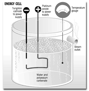
British researchers believe that they have made a
groundbreaking scientific discovery after apparently managing to
"create" energy from hydrogen atoms.
In results independently verified at Bristol University, a team
from Gardner Watts - an environmental technology company based
in Dedham, Essex - show a "thermal energy cell" which appears to
produce hundreds of times more energy than that put into it. If
the findings are correct and can be reproduced on a commercial
scale, the thermal energy cell could become a feature of every
home, heating water for a fraction of the cost and cutting fuel
bills by at least 90 per cent.
The makers of the cell, which passes an electric current
through a liquid between two electrodes, admit that they cannot
explain precisely how the invention works. They insist, however,
that their cell is not just a repeat of the notorious "cold
fusion" debacle of the late 1980s. Then two scientists claimed
to have found a way of generating nuclear energy from a
similar-looking device at room temperature. The findings were
widely challenged and the scientists, Martin Fleischmann and
Stanley Pons, accused of incompetence, fled America to set up
labs in France.
"We are absolutely not saying this is cold fusion, or that we
have found a way round the law of energy conservation," said
Christopher Davies, the managing director of Gardner Watts.
"What we are saying is that the device seems to tap into
another, previously unrecognised source of energy."
According to Mr Davies, the cell is the product of research
into the fundamental properties of hydrogen, the most common
element in the universe. He argues that calculations based on
quantum theory, the laws of the sub-atomic world, suggest that
hydrogen can exist in a so-called metastable state that harbours
a potential source of extra energy.
This theory suggests that if electricity were passed into a
mixture of water and a chemical catalyst, the extra energy would
be released in the form of heat.
After some experimentation, the team found that a small amount
of electricity passed through a mixture of water and potassium
carbonate - potash - released an astonishing amount of energy.
"It generates a lot of heat in a very small volume," said
Christopher Eccles, the chief scientist at Gardner Watts.
The findings of the Gardner Watts team were tested by Dr Jason
Riley of Bristol University, who found energy gains of between
three and 26 times what had been put in.
In a written report, Dr Riley concluded: "Using the apparatus
supplied by Gardner Watts and the procedure of analysis
suggested by the company, there appears to be an energy gain in
the system."
In tests performed for The Telegraph, the cell heated water to
near-boiling, apparently producing more than three times the
amount of energy fed into it.
Scientists admit to being astonished by the sheer size of the
energy increase produced by the cell. "I've never seen a claim
like this before," said Prof Stephen Smith of the physics
department at Essex University.
"In the case of cold fusion, people talked about getting a 10
per cent energy gain or so, which could be explained away quite
easily but this is much too big for that."
Prof Smith said he was sceptical about the theory put forward
by the company. He conceded, however, that scientists had also
been baffled by the source of energy driving radioactivity, as
the key equation involved - Einstein's famous E = MC2
- had yet to be discovered.
According to Prof Smith, if there is a flaw in the company's
claims, it lies in the measurement of the amount of electrical
energy pumped into the cell. It is possible that, as sparks pass
between the electrodes, there is an energy surge which would not
be picked up by the instruments measuring the electrical input.
Prof Smith said: "This needs to be very carefully checked, as
there could be far more energy going in than the makers think."
Prof Smith's views were echoed by Dr Riley, who said: "There's
no doubt that there was a heat rise but I'd like to see a more
thorough investigation of the electrical energy supplied into
the cell."
While many scientists are trying to solve the mystery of the
thermal energy cell, its huge commercial potential has already
caused interest.
Cambridge Consultants, one of Britain's most prestigious
technology consultancies, has teamed up with Mr Davies and his
colleagues to develop a working prototype. "We've had a
multi-disciplinary team working on this, and we're perplexed,"
said Duncan Bishop, head of process development at Cambridge
Consultants.
"We are offering to risk-share on it, as it will need about
GBP200,000 to prove the principle behind it."
According to the Gardner Watts team, it will take about six
months to carry out tests putting the reality of the effect
beyond all doubt. The company then plans to develop a prototype
capable of turning less than one kilowatt of electrical power
into 10 kilowatts of heat.
Mr Davies said: "The technology could be licensed by a company
making household boilers for the domestic market. " He added
that the plan is to have the first thermal energy cell devices
on the market within two years.
---
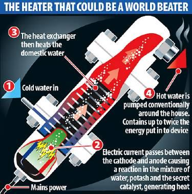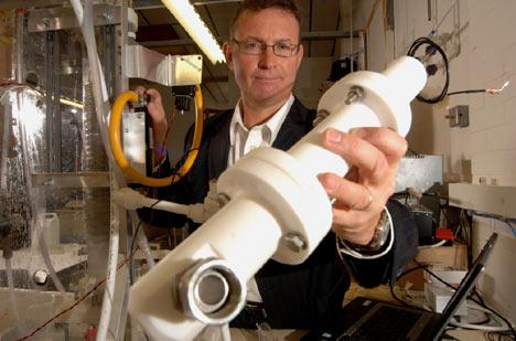
**Hot stuff: Ecowatts boss Paul Calver with
the device**
[**http://www.dailymail.co.uk/pages/live/articles/technology/technology.html?in\_article\_id=481996&in\_page\_id=1965**](http://www.dailymail.co.uk/pages/live/articles/technology/technology.html?in_article_id=481996&in_page_id=1965)
**How This 12-inch Miracle Tube Could Halve Heating Bills**
Amazing British invention creates MORE energy than you put into
it - and could soon be warming your home
It sounds too good to be true - not to mention the fact that it
violates almost every known law of physics.
But British scientists claim they have invented a revolutionary
device that seems to 'create' energy from virtually nothing.
Their so-called thermal energy cell could soon be fitted into
ordinary homes, halving domestic heating bills and making a
major contribution towards cutting carbon emissions.
Even the makers of the device are at a loss to explain exactly
how it works - but sceptical independent scientists carried out
their own tests and discovered that the 12in x 2in tube really
does produce far more heat energy than the electrical energy put
in.
The device seems to break the fundamental physical law that
energy cannot be created from nothing - but researchers believe
it taps into a previously unrecognised source of energy, stored
at a sub-atomic level within the hydrogen atoms in water.
The system - developed by scientists at a firm called Ecowatts
in a nondescript laboratory on an industrial estate at Lancing,
West Sussex - involves passing an electrical current through a
mixture of water, potassium carbonate (otherwise known as
potash) and a secret liquid catalyst, based on chrome.
This creates a reaction that releases an incredible amount of
energy compared to that put in. If the reaction takes place in a
unit surrounded by water, the liquid heats up, which could form
the basis for a household heating system.
If the technology can be developed on a domestic scale, it
means consumers will need much less energy for heating and hot
water - creating smaller bills and fewer greenhouse gases.
Jim Lyons, of the University of York, independently evaluated
the system. He said: 'Let's be honest, people are generally
pretty sceptical about this kind of thing. Our team was happy to
take on the evaluation, even if to prove it didn't work.
'But this is a very efficient replacement for the traditional
immersion heater. We have examined this interesting technology
and when we got the rig operating, we were getting 150 to 200
per cent more energy out than we put in, without trying too
hard.
People are sceptical - but somehow it works
'We are still not clear about the science involved here,
because the physics and chemistry are very different-to
everything that has gone before. Our challenge now is to study
the science and how it works.'
The device has taken ten years of painstaking work by a small
team at Ecowatts' tiny red-brick laboratory, and bosses predict
a household version of their device will be ready to go on sale
within the next 18 months.
The project, which has cost the company GBP1.4million, has the
backing of the Department of Trade and Industry, which is keen
to help poorer families without traditional central heating or
who cannot afford rocketing fuel bills.
Ecowatts says the device will cost between GBP1,500 and GBP2,000,
in line with the price of traditional systems.
The development of the groundbreaking technology results from a
chance meeting between Ecowatts chairman Chris Davies, his wife
Jane and an Irish inventor, Christopher Eccles, while the couple
were on holiday near Shannon in 1998.
After the inventor showed the couple his laboratory
experiments, Mrs Davies, immediately signed a GBP20,000 cheque on
the bonnet of her car and handed it over to Mr Eccles.
He later became chief scientist of Ecowatts' parent company
Gardner Watts, but has since left after 'falling out' with the
company, according to insiders. Sadly, Mrs Davies died three
years ago, so she will be unable to share in the success of her
husband's development of the idea.
Mr Davies, now 75, of Dedham, Essex, was unavailable for
comment last night.
But Ecowatts chief executive Paul Calver said: 'When Jane
Davies whipped out her cheque book, it turned out to be a very
good investment indeed.
'She and Chris were always interested in ecology and now it
looks as if our heat exchanger system is ready to go on sale
soon. We're producing a device in the next nine months to heat
radiators.
'Most British homes rely on gas, and the Government has
admitted there is a problem getting a substitute. Our device
will help solve that.'
Sustainable energy expert Professor Saffa Riffat, of Nottingham
University, has also led a team investigating the system.
He said: 'The concept is very interesting and it could be a
major breakthrough, but more tests are required. We will be
doing further checks.'
---
**Engadget.com**
**Nov 10th 2007**
**EcoWatts "Free Energy" Device Rebuffed, BBC Falls For It.**
**Posted by Conrad Quilty-Harper**
EcoWatts and its fake free energy gadget is back in the
limelight again, with the BBC Breakfast Show falling hook, line,
and sinker in an interview with the company's "CEO" Paul Calver.
Calver stated that "we're still getting to the question of why
it works," explaining to a BBC presenter his bewilderment at his
very own creation. The response from the interviewer? "The point
is it does." Unfortunately, the point is that it almost
certainly doesn't. Ben Goldacre used his excellent Bad Science
Guardian column this week to dig up some dirt on the dodgy
company, and managed to find a scientist who gave his stamp of
approval to a similar free energy gadget four years back: "Using
the apparatus provided, it's true, this scientist could get
incredible results: the meters would read zero, and yet water
would boil in around five minutes. Because the meters provided
weren't working." The company that provided this former gadget
along with the "broken" meters? EcoWatts.
---
**WO 00/25320**
**"Energy Generation"**
**(4 May 2000) Cl. G21B 1/00**
**Christopher Eccles**
**Abstract**
Methods and apparatus are described for releasing energy from
hydrogen and/or deuterium atoms. An electrolyte is provided
which has a catalyst therein suitable for initiating transitions
of hydrogen and/or deuterium atoms in the electrolyte to a
sub-ground energy state. A plasma discharge is generated in the
electrolyte to release energy by fusing the atoms together.
**Description**
The present invention relates to the generation of electricity,
and more particularly to the release of hydrogen and fusion of
light atomic nuclei.
Normally, fusion processes are able to be initiated only at
extremely high temperatures, as found in the vicinity of a
nuclear fusion (uranium or plutonium) detonation. This is the
principle of most thermonuclear bombs. Such a release of energy
is impractical as a means of providing the power to generate
electricity and heat for distribution, as it occurs too rapidly
with too high a magnitude for it to be manageable.
In recent years, many attempts have been made to initiate
controlled fusion processes at high temperatures by the
enclosure of a region of plasma-discharge within a confined
space, such as a toroidal chamber, using electromagnetic
restraint. Such attempts have met with little commercial success
to date as systems which employ such a technique have so far
consumed more energy than they have produced and are not
continuous processes.
Another approach which has been attempted in order to achieve
fusion of light nuclei has been the so-called "cold fusion"
technique, in which deuterium atoms have been induced to tunnel
into the crystal lattice of a metal such as palladium during
electrolysis. It is claimed that the atoms are forced together
in the lattice, overcoming the repulsive electrostatic force.
However, no clear and unambiguous demonstration of successful
cold fusion has yet been presented publicly.
The present invention provides a method of releasing energy
comprising the steps of providing an electrolyte having a
catalyst therein, the catalyst being suitable for initiating
transitions of hydrogen and/or deuterium atoms in the
electrolyte to a sub-ground energy state, and generating a
plasma discharge in the electrolyte. The applicants have
determined that this method generates substantially more energy
than the power input used to generate the plasma, whilst doing
so in a controllable manner.
Preferably, the plasma discharge is generated by applying a
voltage across electrodes in the electrolyte and an intermittent
voltage has proved particularly useful in increasing the level
of energy generation. It also provides a means of controlling
the process to maintain a consistent level of energy production
over a significant period of time.
The application of a voltage higher than necessary to generate
plasma also is beneficial to the process and will be typically
in the range of 50 V to 20,000 V and preferably between 300 V
and 2,000 V, but may be higher than 20,000 V, whereas in
conventional electrolysis techniques low voltages of about 3
volts are used and applied continuously across the electrodes.
The applied voltage may be DC or provided at a switching
frequency of up to 100 KHz. The duty cycle of the applied
voltage is preferably in the range of 0.5 to 0.001, but may be
even lower than 0.001. During the pulse period a monomolecular
layer of metal hydride may be formed at the cathode-Helmholtz
layer interface and subsequently decays to form gas in the
nascent state comprising comprising monoatomic hydrogen and/or
deuterium. The waveform of the applied voltage may be
substantially square shaped. Whilst application of DC to the
electrode does produce the metal hydride and monoatomic hydrogen
and/or deuterium, the use of a pulsed voltage has been found to
be more efficient as most dissociation of the hydride then
occurs between the pulses.
In applications where the electrolyte is flowed past the
electrodes it may be preferable to use two separate cathodes,
the first of which will be engineered to optimize production of
H/D atoms and the second of which will provide the plasma
discharge. In this instance the direction of flow of the
electrolyte is from first to second cathode. The design of the
apparatus seeks to direct the flow of electrolyte to maximize
contact of monoatomic H or D atoms with the plasma. The
characteristics and magnitude of the voltages applied to each
cathode are preferably similar, but may have different duty
periods.
In a preferred embodiment, the cathode design and applied
voltage are such as to provide a current density of 400,000 amps
per square meter or even greater. More preferably, the current
density at the cathode is 50,000 amps per square meter or above.
In carrying out a preferred method in accordance with the
invention, it has been found that the process may be assisted by
initial heating of the electrolyte, which may be water or a salt
solution, prior to applying electrical input to the vessel. A
temperature in the range of 40 to 100 C, or more preferably 40 deg
to 80 deg C, has been found to be particularly beneficial.
The ratio of water to deuterium oxide (D2)) in the electrolyte
may be varied to control the energy generation. In some
circumstances it may be preferable to use "light" water H2O
alone and in others to use D2O alone. Additionally,
the amount of catalyst added to the electrolyte may be varied as
a controlling factor and preferably lies in the range of 1 to 20
mMol.
In preferred embodiments, the method includes the step of
generating a magnetic field in the region of the electrodes. The
intensity and/or frequency of the current used to generate the
field may be adjusted to move the plasma discharge away from the
electrode from which it is struck in order to minimize erosion
and extend the operating life of the system. Only slight
separation may be required to achieve this effect.
In further preferred embodiments, the heat generated by the
process may be removed and utilized by way of a number of known
and proven technologies including the circulation of the
electrolyte through a heat exchanger, or using heat pipes to
produce heating, or alternatively to produce electricity using a
pressurized steam cycle or a low-boiling-point fluid turbine
cycle, or by other means.
The present invention further provides apparatus for carrying
out methods discloded herein comprising an anode, first and
second cathodes, a reaction vessel having an inlet and an
outlet, means for feeding an electrolyte through the vessel from
its inlet to its outlet, the electrolyte having a catalyst
therein suitable for initiating transitions of H and/or D atoms
in the electrolyte to a sub-ground energy state, menas for
applying a voltage across the anode and the first cathode to
form H and/or D atoms, and means for applying a voltage across
the anode and second cathode to generate a plasma discharge from
the first cathode.
During the methods described herein, atoms of H and/or D are
believed to undergo a fundamental change in their structure by
exchange of photons with salts in solution. The applicants
believe that this change, and the observed phenomena, can be
explained as set out below.
It is well known that a system comprising a spherical shell of
charge (the electron path) located around an atomic nucleus
constitutes a resonant cavity. Resonant systems act as the
repository of photon energy of discrete frequencies. The
absorption of photon energy by a resonant system excites the
system to a higher-energy state. For any spherical resonant
cavity, the relationship between a permitted radius and the
wavelength of the absorbed photon is:
2 pi r = n lambda
(pi = 3.14...)
where n is an integer
and lambda is the wavelength
For non-radiating or stable states, the relationship between
the electron wavelength and the allowed radii is:
(2) 2 pi [nr1] = 2 pi r(n) =
n lambda(1) = lambda(n)
where n = 1
or n = 2, 3, 4...
or n = 1/2, 1/3, 1/4...
and lambda(1) = the allowed wavelength for n = 1
r(1) = the allowed radius for n = 1
In a hydrogen atom (and the following applies equally to a D
atom), the ground state electron-path radius can be defined as
r(0). There is normally no spontaneous photon emission from a
ground state atom and thus there must be a balance between the
centripetal and the electric forces present. Thus:
(3) [ m(e) . v12 ]
/ r(0)= Ze2 / ( 4 pi . epsilon(0)
. r(0)2 )
where m(e) = electron rest mass
v1 = ground state electron velocity
e = elementary charge
epsilon(0) = electric constant (sometimes referred to
as the permitivity of free space)
Z = atomic number (for H, 1)
Looking first at the excited (higher energy) states, where the
hydrogen atom has absorbed photons of discrete
wavelength/frequency (and hence energy), the system is again
stable and normally non-radiating, and to maintain force
balance, the effective nuclear charge becomes Zeff = Z/n, and
the balance equation becomes:
(4) [ m(e) . vn2 ] / nr(0)
= [ e2 / n ]
where n = integer value of excited state (1, 2, 3...)
vn = electron velocity in the nth excited state.
He absorption of radiation by an atom thus results in an
excited state which may decay to ground state, spontaneously, or
be triggered to do so, resulting in the re-release of a quantum
of energy in the form of a photon. In any system consisting of a
large number of atoms, transitions between states are occurring
continuously and randomly and this activity gives rise to the
observable spectra of emitted radiation from H.
Each value of n corresponds to a transition which is permitted
to occur when a resonant photon is absorbed by the atom. Integer
values of n represent the absorption of energy by the atom.
Fractional values of are allowed by the relationship between
the standing wavelength of the electron and the radius of the
electron-path, given by (2), above. To maintain force balance,
transitions involving fractional values for n must effectively
increase the nuclear charge Z to a figure Zeff, and
reduce the radius of the electron-path accordingly. This is
equivalent to the atom emitting a photon of energy while in the
accepted ground state, effecting a transition to a sub-ground
state. Because the accepted ground state is a very stable one,
such transitions are rarely encountered but the applicants have
discovered that they can be induced if the atom is in close
proximity to another system which acts as a "receptor-site" for
the exact energy quantum required to effect the transition.
The emission of energy by a hydrogen atom in this way is not
limited to a single transition "down" from ground state, but can
occur repetitively and, possibly, transitions from 1/3, 1/4,
1/5, etc. states may occur as a single event if the energy
balance of the atom and the catalytic system is favorable. Of
course, the usual uncertainty principles forbid the
determination of the behavior of any individual atom, but
statistical rules govern the properties of any macroscopic
(>109) quanta system.
When a "ground-state" hydrogen atom emits a photon of around 27
eV, the transition occurs to the ao/2state as demonstrated above
and the effective nuclear charge increases to +2e. A new
electron path radius is reduced. The potential energy of the
atom in its reduced-radius state is given by
V = -{ Z(eff)e2 / [ 4 pi epsilon(o)
(a(o) / 2)]} = - { 4 x 27.178} = -108.7 eV
The kinetic energy, T, of the reduced electron path is given by
T = - [ V / 2 ] = 54.35 eV
Similarly, it can be seen that the kinetic energy of the ground
sate electron path is about 13.6 eV. Thus there is a net change
in energy of about 41 eV for the transition:
H{ Z(eff) = 1 ; r = a(o) } to H{ Z(eff)
= 2 ; r = a(o) / 2 ]
That is to say, of this 41 eV, about 27 eV is emitted as the
catalytic transfer of energy occurs, and the remaining 14 eV is
emitted on restabilization to the force balance.
The radial "ground-state" can be considered as a superposition
of Fourier components. If integral Fourier components of energy
equal to m x 27.2 eV are removed, the positive electric path
inside the electron path radius increases by
(m) x 1.602 x 10⁻¹⁹C
The resultant electric field is a time-harmonic solution of the
Laplace equations in spherical coordinates. In the case of the
reduced-radius H atom, the radius at which force balance and the
non-radiative condition are achieved is given by
R(m) = a(o) / [m+1 ]
Where m is an integer.
From the energy change equations given above, it will be
appreciated that, in decaying to this radius from the so-called
"ground-state", the atom emits a total energy equal to
(5) [ ( m + 1 )2 - 12 ] x
13.59 eV
The applicants have found that such energy emissions as take
place according to (5), above, only appear to occur when the H
or D is found in the monoatomic (or so-called "nascent") state.
Molecular H might be made to behave similarly, but the
transition is more difficult to achieve owing to the higher
energies involved.
In order to achieve the transition in monoatomic H or D, it is
necessary to accumulate the molecular form in the gas phase on a
substrate such as nickel (Ni) or tungsten (W) which favors the
dissociation of the molecule. As well as being dissociated into
the monoatomic form, the H or D should be bound to the catalytic
system to initiate the reaction. The preferred method of
achieving this is by electrolysis using cathode material which
favors dissociation.
The applicants have discovered that the catalytic systems which
encourage transitions to sub-ground-state energies are those
which offer a near-perfect energy couple to the [ m x 27.2 ] eV
needed to "flip" the atom of H or D. It appears from experiment
that the effective sink of energy provided by the catalyst need
not be precisely equal to that emitted by the atom. Successful
transitions have been achieved when there is an error of a s
much as +- 2% between the energy emitted by the atom and that
absorbed by the catalytic system. One possible explanation for
this is that, in a macroscopic sized system, although the
transitions are initiated by a close match in energy level, such
discrepancies as arise are manifested as an overall loss or gain
in the kinetic energies of the recipient ionic systems. It is
thought that spectroscopic analysis of active H or D catalytic
systems may provide evidence of this.
One catalyst that has been found to initiate the transition to
the ao/n state is rubidium in the Rb+ ionic species. If a salt
of Rb, such as the carbonate Rb2CO3 is
dissolved in either water or deuterium oxide (heavy water), a
substantial dissociation into Rb+ and (CO3)2-
ions takes place. If the Rb+ ions are bound closely to
monoatomic H or D, the transition to the ao/n state is
encouraged by the removal of a further electron from the Rb ion,
by provision of its second ioization energy of about 27.28eV.
Thus:
Rb+ +H { a(o) / p ] +27.28 eV
-->
Rb2+ + e- +H { a(o) / [ p = 1]
} + { [ ( p + 1 )2 -p2 ] x 13.59 } eV
Where p represents an integral number of such transitions for
any given H and D atom and by spontaneous re-association:
Rb2+ + e- = Rb+ +27.28 eV
Thus, the Rb catalyst remains unchanged in the reaction and
there is a net yield of energy per transition.
Other catalytic systems can be used which have ionization
energies approximating to [ m x 27.2 ] eV, such as titanium in
the form of Ti2+ ions and potassium in the form
of K+ ions.
The applicants believe that the above explanation is consistent
with currently accepted quantum theory as discussed below.
Commencing with the equations of Rydberg and Scroedinger it can
be shown that fractional numbers for the quantum theory energy
states in H yield possible transitions which result in emissions
at frequencies which are in accord with observed UV and X-ray
spectra. It is therefore possible that the conditions conducive
to initiating such transitions may be artificially reproduced in
the laboratory under certain circumstances.
The Rydberg formula for the frequency of emitted radiation from
a transition in monoatomic H is:
V = R(h)c( 1 / n(2)2 - 1 / n(1)2
)
Where:
V is the frequency of the emitted photon
R(h) is the Rydberg constant, 1.097373 c 107
m-1
C is the speed of light in vacuo, 2.997 x 10³ ms-1
and
n(1), n(2) are the transition states.
It can be seen from the above that, if the resultant energy
state of the H atom is that which requires n(2) to be
equal to 1/2 , emissions will occur which are of higher
frequency than the observed Lyman 2-1 transition in the
ultra-violet at 2.467 x 1o15 Hz (about 121 nm). There
is, indeed, an observed emission at a wavelength of about 30.8
nm, which appears to be confirmed by recent studies of galactic
cluster emissions by Bohringer, *et al*. (*Scientific
American*, January 1999) and it is difficult for the
inventor to conceive of any other quantum-mechanical event which
would give rise to such an emission, other than a transition, in
accord with the above theory, from 1 to 1/2 in nascent H.
As can be seen from the above use of the standard Rydbberg
equation, such behavior of H in the monoatomic state views the
conventional H "ground-state" as one of many stable
electronically-preferred states for single H atoms.
To summarize, a proliferation of H or D atoms is produced which
may have had significantly diminished electron-path-radii by
virtue of exchange of photons with their envronment. These atoms
appear to be relatively unreactive chemically and appear not to
readily take the molecular form H-H or D-D. This is a fortunate
property which has significance and enables fusion pathways, as
described below.
The fusion of light nuclei, H and D, to form heavier elements
such as He is one which has traditionally been encouraged by
subjecting the reactants to extremes of temperature and
pressure. This has been necessary because there is a large
electric charge barrier to overcome in order to bring nuclei
close enough for fusion to occur.
Using atoms with a diminished electron path radius, adjacent
nuclei may experience a corresponding reduction in electric
barrier and internuclear separations may become smaller. With
reductions in internuclear separation, fusion processes become
more probable, and more easily occasioned.
There are two principle fusion pathways for D atoms. The first
is:
1D2 + 1D2 = 2He3
+ 1n0
where two D nuclei fuse to produce an isotope of He and a free
neutron, which subsequently decays (half-life 6.48 x 10²
S), with emission of a beta particle of medium energy (about 0.8
MeV), and a type of neutrino, to become a stable proton.
The second is:
1D2 + 1D2 = 1T3
+ 1H1
where the two D nuclei fuse to produce the isotope of H known
as tritium (T) and a free stable proton. The tritium eventually
decays (half-life 12.3 years), with emission of a beta particle
of very low energy (about 0.018 MeV), to become 2He3.
Of the two, the second fusion path is preferred for the
peaceful exploitation of its energy yield, because the fusion
products are relatively harmless on production, and decay to
completely innocuous species within a short time, emitting
radiation which can be effectively shielded by a thin sheet of
aluminum foil or by 10 mm of acrylic plastic, for example.
When D nuclei are forced together under high temperature and
pressure conditions (as in a thermonuclear bomb), there is a
greater than 50% probability for the first pathway to be the
dominant one. This is because the high temperature process takes
no account of nuclear alignment at the point of fusion. It is
actually a matter of focusing nuclei together indiscriminately
and hoping that enough fuse to produce an explosion. The
applicants believe, however, in accord with established theory,
that it is the alignment of the nuclei with respect to the
charges in each nucleus which ultimately determines the
favorable fusion path.
In order to achieve a higher probability for the second, less
hazardous pathway, the approaching nuclei need to have time to
align electrostatically such that the proton-proton separation
is at a maximum. This can only be achieved at far lower energies
than those found in a thermonuclear bomb. By the use of entities
with diminished electron-path-radii, and correspondingly
potentially smaller internuclear distances, fusion can be
initiated at lower temperatures (and consequently lower
energies), allowing for the charge-related alignment necessary
to achieve a high probability for the second, tritium-forming,
pathway. By introducing D of diminished electron-path-radius
into the plasma discharge which is confined within the water in
the vessel itself, fusion may be initiated. Temperatures of the
order of 6000 deg K are obtained within certain plasma discharges
and this, coupled with multiple quantum transitions to produce D
of diminished electron-path-radius, produces a substantial yield
of energy from the two-stage process.
Another possible but less likely fusion pathway for hydrogen
atoms is:
1H1 + 1H1 = 1D2
+ Beta+ + tau
whereby Beta+ is produced as one of the products.
Embodiments of the invention will now be described by way of
example and with reference to the accompanying schematic
drawings, wherein:
**Figure 1** shows an apparatus for carrying out a method in
accordance with the invention on a relatively small scale;
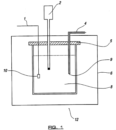
**Figure 2** shows a system for operating and measuring the
performance of the apparatus of Figure 1;
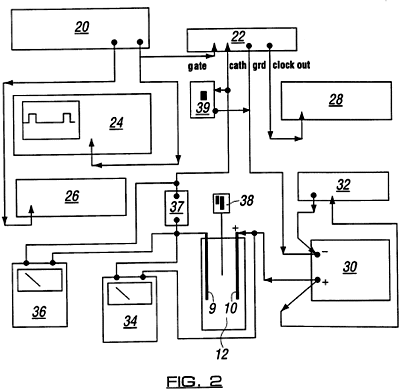
**Figure 3** shows a circuit diagram high voltage, high
frequency switching circuit for the system of Figure 2;
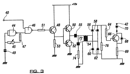
**Figure 4** shows an apparatus for carrying out a method in
accordance with the invention on a larger scale than that of the
Figure 1 apparatus; and
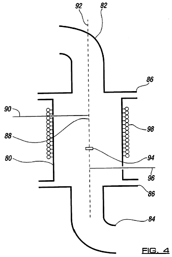
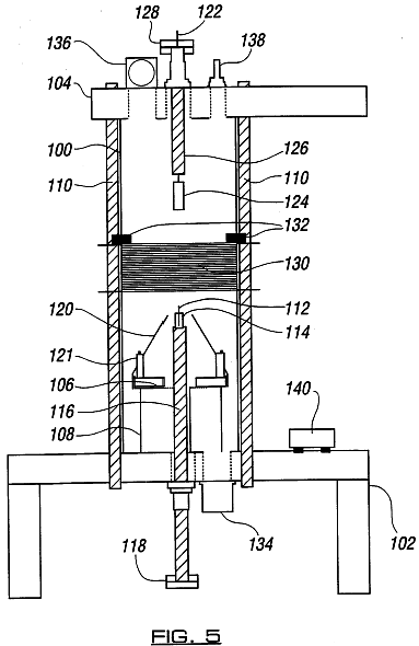
**Figure 5** shows a further apparatus for carrying out a
method of the invention which includes two cathodes.
The apparatus of Figure 1 enables the generation of energy
according to the principles of the invention in the laboratory.
Any risk of thermal runaway is minimized whilst demonstrating
that the level of energy release from the two stages is far in
excess of that which would result from any purely chemical or
electrochemical activity. It also enables easy calorimetry, safe
ducting away of off-gases, and of subsequent extraction of
liquid for titration (to demonstrate that no chemical action
takes place during the operation of the apparatus).
A 250 ml beaker is provided with a glass quilt or expanded
polystyrene surround 6 to act as insulation. This can include an
inspection cut-out so that the area around the cathode 9 can be
observed from outside. The beaker contains 200 ml of water, into
which is dissolved a small quantity of potassium carbonate so as
to give a solution of approximately 2 mMol strength. A platinum
wire 1 is earthed to the laboratory reference ground plane. The
anode 10, a sheet of platinum foil of approximately 10 mm2 in
area, is attached to this wire by mechanical crimping. A digital
thermometer 2 is inserted into the liquid in the vessel. A 0.25
mm diameter tungsten wire cathode 9 is sheathed in borosilicate
glass or ceramic tube 4 and sealed at the end immersed in the
electrolyte so as to expose 10 mm to 20 mm of wire in contact
with the liquid. The entire assembly of lead wires and the
thermometer is carried by an acrylic plate 5 which enables of
easy dismantling and inspection of the apparatus.
A supply of up to 360 volts DC, capable of supplying up to 2
amperes, is arranged external to the described apparatus. The
positive terminal of this supply is connected to one pole of an
isolated high-voltage switching unit. The other pole of the
switch is connected to the tungsten wire cathode 9 externally of
the apparatus.
To operate the apparatus, the solution 8 is initially brought
up to between 40 deg C and 80 deg C either by preheating outside the
apparatus or by passing power through a heating element in the
solution (not shown). When the solution is between these
temperatures it is either transferred to the above apparatus or,
if a heating element is used, this is turned off.
With all connections made as described, the switch is set to
operate at a duty cycle of 1% and a pulse repetition frequency
of 100 Hz. It will be seen through the inspection cut-out that
an intense plasma-arc is intermittently struck under the water
at or near the cathode. If equipment is available to monitor the
current drawn, it will be seen that the system consumes in the
region of 1 watt when the switching circuit is operating. It
will be seen by the rapid rise in temperature in the apparatus
that far more energy is being released than can be accounted for
by the electrical input. As a comparison, a heater element can
be substituted for the electrodes and operated at 1 watt and the
effects observed. There is really no need for sophisticated
calorimetry to verify that large quantities of energy are being
released close to the cathode of the equipment, such is the
magnitude of the reaction for the process, as compared to a test
with a resistive heating element of the same input power.
The data obtained from a representative one-hour session with
this apparatus is shown in Table 1, below:
**Table 1**
*Pre-Run Measurements* :
Commencing volume of electrolyte = 0.200 liter
Commencing temperature of cell = 39.200 deg C
Laboratory ambient temperature = 20.500 deg C
Specific heat capacity of vessel = 70.300 J. degC-1
Specific heat capacity of electrolyte = 4180.000 J. I-1
degC-1
Steady RMS voltage = 4.0 volts
Steady RMS current = 0.067 amps
*Post-Run Results* :
Duration of input = 3600 seconds
Final volume of electrolyte = 0.180 liter
Final temperature of cell = 93.6 deg C
Steady RMS voltage = 6.7 volts
Steady RMS current = 0.122 amps
Time-averaged power in = 0.506 watts
*Results Summary* :
Vessel gain = 3824.320 Joules
Electrolyte gain = 43181.740 Joules
Radiated power = 38681.030 Joules
Evaporated loss = 48509.240 Joules
Total Energy In = 1820.070 Joules
Total Energy Output = 134196.300 Joules
It can be seen from this table that the total energy input
during this test was measured at 1820 J and, taking as a rough
guideline that 200 ml of water requires the input of 838 J of
energy to raise it by 1 deg C, then by direct heating the water
would be expected to rise by some 2 deg C, bearing in mind
radiative losses. In fact, during the experiment the water
temperature was raised from 39.2 deg C to 93.6 deg C and considerable
steam was also liberated. Furthermore, the calculated energy
output of 134196 J does not take account of secondary effects
such as light-energy output and Faradaic electrolysis
A system suitable for operating the apparatus of Figure 1 is
illustrated in block diagram in Figure 2. A pulse generator 20
supplies a variable duty-cycle pulse waveform to to a
high-voltage switch unit 22. The pulse waveform may be monitored
on an oscilloscope 24 and its repetition frequency is displayed
on a first frequency counter 26. A second frequency counter 28
is provided to monitor the clock speed of the switch unit 22.
Power supply 30 is operable to apply a voltage between 0 and 360
V to an electrode of the apparatus 12, shown in Figure 1. The
voltage level may be read from a digital multimeter 32. The RMS
voltage across the electrodes 9 and 10 is indicated on a
multimeter 34 and the RMS current passing between the electrodes
is shown on another multimeter 36, by measuring the voltages
developed across a 1 ohm resistor 37. The temperature in the
apparatus 12 is indicated on a dip temperature probe 38. The
switch unit 22 may be bypassed by a push button switch 39 to
apply a constant voltage across the electrodes.
A circuit diagram of the switch unit 22 is shown in Figure 3.
In the system of Figure 2, input 40 is connected to the output
of pulse generator 20. The output 42 of the switch unit is
connected to the cathode of the apparatus 12. Two NAND gates 44
and 46 are two fourths of a Schmitt-trigger 2 input NAND gate
chip type 4093. NAND gate 44 operates as an astable
multivibrator, with its repetition frequency set by a preset
resistor 45. The output of gate 44 is fed to one in-out of NAND
gate 46, the other input forming circuit input 40. The output of
NAND gate 46 is connected to a three-transistor amplifier
consisting of transistors 48, 50 and 52. The amplifier is in
turn connected to one end of the primary of a transformer 54,
the other end being connected to earth. The transformer output
is fed to a bridge rectifier formed from diodes 56, 58, 60 and
62.
The rectifier output is fed via a resistor 64 to the gate of an
insulated gate bipolar transistor 6 (IGBT). The load of the
apparatus 12 is connected in the drain circuit of the IGBT. A 15
kV diode 68 is connected between the drain and the source of the
IGBT 66 to protect the IGBT from the sizeable EMI
emissions from the plasma discharges in the apparatus 12 and
avoids damage to this sensitive semiconductor. A further diode
70 is provided between the drain of the IGBT and the circuit
output 42 to act as an EMI blocker in a similar way. A standard
20 mm 5 amp quick-blow fuse 69 is connected between the source
of the IGBT and ground in order to protect the device against
over-current.
The operation of the circuit of Figure 3 is as follows. The
repetition frequency in NAND gate 44 is preferably set to
between 4 and 6 MHz. Pulse generator 20 is adjusted to set the
duty of the switching. On receipt of an external pulse from the
generator, NAND gate 46 passes a packet of 4 to 6 MHz square
waves to the amplifier. The amplifier has considerable current
gain and enable the primary of the transformer 54 to be driven
resonantly with the RC circuit formed by capacitor 72 and
resistor 74 which are connected in parallel therewith. The
transformer 54 has a step-up ratio of 2:1 and a 4 to 6 MHz
signal of approximately 19 volts appears across the bridge
rectifier. The impedance of the rectifier output is essentially
determined by a parallel resistor 76, such that the switch-on
and switch-off time of the IGBT 66 is very fast. Thus, there is
never a point in the operation of the device when it is
dissipating any measurable power. The load of the apparatus 12
is placed in the drain circuit of the IGBT, which is therefore
operating in "common-source" mode to ensure that its source
terminal never rises above the high-side ground potential. This,
again, is a configuration which uses excess input power. This
circuit ensures a rise time of the switched waveform which isles
than 10 nS and a fall time which can be as low as 30 nS at
modest supply voltages.
Preferred component values and types for the circuit of Figure
3 are as follows:
Transistors 4, 50 = 2N 3649
Transistor 52 = 2N 3645
Diodes 56, 58, 60, 62 = BAT85 Schottky
Transformer 54 = RS195-460
IGBT 66 = GT8Q101
Diode 68 = 15 kV EHT
Diode 70 = 1N1198A
Resistor 47 = 1.8 kOhm
Resistor 51 = 33 Ohm
Resistor 53 = 220 Ohm
Resistor 74 = 56 Ohm
Resistor 76 = 560 Ohm
Resistor 64 = 56 Ohm
Capacitor 49 = 10 pF
Capacitor 55 = 33 nF
Capacitor 72 = 22 pF
A second apparatus for carrying out the invention is
illustrated in Figure 4. This apparatus comprises a tubular
chamber 80, which may be constructed from a nonmagnetic metal or
metal alloy material such as, but not exclusively, aluminum or
Duralumin, or alternatively may be constructed from a
non-permeable ceramic material or from borosilicate glass. The
tubular chamber 80 is constructed in flanged form to allow of
its incorporation into a system of pipework via flanges 82 and
84 and gaskets 86. Entering the chamber 80 are two electrodes,
the cathode 88 being shaped so as to present a circular plate
opposite the cathode 88. The distance between the cathode tip
and the anode plate should be approximately equal to the radius
of the chamber 80. The cathode may be constructed from tungsten,
zirconium, stainless steel, nickel or tantalum, or any other
metallic or conductive ceramic material which may contribute to,
or occasion, the dissociative process described above. The anode
may be constructed from platinum, palladium, rhodium or any
other inert material which does not undergo any significant
level of chemical interaction with the electrolyte.
Surrounding the chamber 80, and concentric with it, is a
winding 98 of enameled copper or silver wire of diameter 0.1 to
0.8 mm consisting of up to several thousand turns of the wire.
The purpose of this winding is to create an axial magnetic field
inside the chamber 80.
Electrolyte comprising deuterium oxide, in combination with
ordinary "light" water in varying proportions, and containing
high-molarity salts of, but not exclusively of, potassium,
rubidium or lithium, or combinations of such salts, is pumped
through the chamber 80, in a direction such that the anode is
downstream of the cathode.
The anode lead wire 96 is connected to the ground plane or zero
volts. The cathode 88 is connected to a variable source of
between 50 and preferably 2000 volts negative with respect to
the grounded anode 94, but may be couple to a voltage of up to
several tens of thousands of volts negative with respect to such
anode 94. To enhance performance of the invention, the negative
voltage may be supplied in the form of pulses having a duty
cycle between 0.001 and 0.5
The winding 98 is energized with an alternating voltage such as
to provide a current flow of typically between 0.5 and 1.5 amps
initially. The frequency of the applied alternating voltage
should be variable from DC up to 15 KHz and may, in addition, be
synchronous with pulses applied to the cathode 88.
Under these conditions, a plasma arc will strike close to the
cathode 88. The intensity and frequency of the current flowing
in winding 98 may be adjusted to provide for the removal of the
plasma arc from the immediate vicinity of the cathode 88 to
avoid excessive evaporation of the material from the cathode 88.
The volume of electrolyte pumped through chamber 80 and past
the plasma arc may be varied such as to stabilize the
temperature of such electrolyte in a closed system at below its
boiling point.
Heat may be extracted from the electrolyte by passing it
through a heat exchanger before its re-introduction into the
chamber 80. Provision may be made to top-off the water-deuterium
content of the electrolyte as this becomes depleted by operation
of the apparatus. The system may operate at a range of pressures
to facilitate heat removal.
A further apparatus for carrying out the invention, similar to
that of Figure 4, is shown in Figure 5 on a scale of
approximately 1:2:5. It comprises a borosilicate reaction tube
100 supported at one end on a machined nylon support bridge 102.
A second machined nylon element 104 is mounted across the other
end of the tube. The bridge 102 and element 104 are clamped
against the tube 100 by 8 mm threaded stainless steel studs 110.
A first cathode 106 is in the form of a nickel wire mesh. It is
mounted towards one end of tube 100 on a stainless steel support
108. Electrical connection to the first cathode 106 is via a
PVS-sleeved wire (not shown).
A second cathode 112 consists of a 0.5mm diameter length of
tungsten wire provided within a drilled macor ceramic sheath
114, which is in turn placed within a 10 mm stainless steel tube
116. Tube 116 passes through the support 102 and has a perspex
end cap 118 on the external end through which the second cathode
112 passes. A PVC funnel 120 is provided around the second
cathode and is tapered towards it, with the cathode tip adjacent
the narrower open end thereof. The funnel is supported on
sleeves 121 provided on the stainless steel support 108.
The anode comprises a 0.25 mm diameter platinum wire 122 which
is connected at one end within the tube 100 to a sheet of
platinum foil 124. Like the second cathode 11s, the anode is
provided within a 10 mm diameter stainless steel tube 126, which
passes through nylon element 104 and is closed at its external
end by a Perspex end cap 128. Platinum wire 122 passes through
the end cap 128.
A plasma deflection coil 130 is mounted within tube 100 between
the anode 124 and cathodes 106, 112. Electrical power is fed to
the coil via connectors 132.
Electrolyte is supplied to the tube 100 via a brass inlet 134
provided through the support bridge 102 and flows out through
nylon element 104 via a brass outlet 136. An additional brass
outlet 138 also is provided in nylon element 104 to allow the
electrolyte to be sampled during operation of the apparatus.
Fuse holders and cable connectors for the apparatus are provided
in a unit 140 mounted on the support bridge 102.
The apparatus of Figure 5 is operated in a similar manner to
that of Figure 4, as discussed above. The primary distinction is
that two cathodes 106, 112 are employed in place of a single
cathode. In use, electrolyte is fed through the tube 100, past
the electrodes, from inlet 134 to outlet 136. A pulsed voltage
is applied to the first cathode 106 such that a layer of metal
hydride is formed on its surface during the voltage pulses and
subsequently dissociates to form nascent monoatomic H/D. The
applied voltage characteristics are selected to optimize the
production rate of the monoatomic H/D. These products are
channeled toward the second cathode 112 by the funnel 120. A
voltage is applied to the second cathode 112 to generate a
plasma discharge thereat.
The characteristics and magnitudes of the voltages applied to
the first and second cathodes may be similar, but it may be
advantageous for different duty periods to be employed for
respective cathodes. This cathode arrangement with the second
cathode downstream of the first seeks to maximize contact
between the monoatomic H/D and the plasma and therefore the
efficiency of the apparatus. This is further assisted by the
funnel 120.
---
**US Patent Application 20050236376**
**Christopher Robert ECCLES**
**( October 27, 2005 )**
**Energy Generation**
**Abstract**
Methods and apparatus are described for releasing energy from
hydrogen and/or deuterium atoms. An electrolyte is provided
which has a catalyst therein suitable for initiating transitions
of hydrogen and/or deuterium atoms in the electrolyte to a
subground energy state. A plasma discharge is generated in the
electrolyte to release energy by fusing the atoms together.
Inventors: Eccles, Christopher Robert; (Colchester, GB)
Correspondence Name and Address:
MCANDREWS HELD & MALLOY, LTD
500 WEST MADISON STREET
SUITE 3400
CHICAGO
IL
60661
U.S. Current Class: 219/121.36; 373/22
U.S. Class at Publication: 219/121.36; 373/022
Intern'l Class: A61N 001/18; B23K 009/00
**Description**
[0001] The present invention relates to the generation of
energy, and more particularly to the release of energy as a
result of both a state-transition in hydrogen and fusion of
light atomic nuclei.
[0002] Normally, fusion processes are able to be initiated only
at extremely high temperatures, as found in the vicinity of a
nuclear fusion (uranium or plutonium) detonation. This is the
principle of most thermonuclear bombs. Such a release of energy
is impractical as a means of providing the power to generate
electricity and heat for distribution, as it occurs too rapidly
with too high a magnitude for it to be manageable.
[0003] In recent years, many attempts have been made to
initiate controlled fusion processes at high temperatures by the
enclosure of a region of plasma-discharge within a confined
space, such as a toroidal chamber, using electromagnetic
restraint. Such attempts have met with little commercial success
to date as systems which employ such a technique have so far
consumed more energy than they have produced and are not
continuous processes.
[0004] Another approach which has been attempted in order to
achieve fusion of light nuclei has been the so-called "cold
fusion" technique, in which deuterium atoms have been induced to
tunnel into the crystal lattice of a metal such as palladium
during electrolysis. It is claimed that the atoms are forced
together in the lattice, overcoming the repulsive electrostatic
force. However, no clear and unambiguous demonstration of
successful cold fusion has yet been presented publicly.
[0005] The present invention provides a method of releasing
energy comprising the steps of providing an electrolyte having a
catalyst therein, the catalyst being suitable for initiating
transitions of hydrogen and/or deuterium atoms in the
electrolyte to a sub-ground energy state, and generating a
plasma discharge in the electrolyte. The applicants have
determined that this method generates substantially more energy
than the power input used to generate the plasma, whilst doing
so in a controllable manner.
[0006] Preferably, the plasma discharge is generated by
applying a voltage across electrodes in the electrolyte and an
intermittent voltage has proved particularly beneficial in
increasing the level of energy generation. It also provides a
means of controlling the process to maintain a consistent level
of energy production over a significant period of time.
[0007] The application of a voltage higher than that necessary
to generate plasma is also beneficial to the process and will be
typically in the range 50V to 20000V and preferably between 300
and 2000V, but may be higher than 20000V, whereas in
conventional electrolysis techniques low voltages of about 3
volts are used and applied continuously across the electrodes.
[0008] The applied voltage may be DC or provided at a switching
frequency of up to 100 kHz. The duty cycle of the applied
voltage is preferably in the range 0.5 to 0.001, but may be even
lower than 0.001. During the pulse period a monomolecular layer
of metal hydride may be formed at the cathode-Helmholtz layer
interface and subsequently decays to form gas in the nascent
state comprising monatomic hydrogen and/or deuterium. The
waveform of the applied voltage may be substantially square
shaped. Whilst application of DC to the electrode does produce
the metal hydride and monatomic hydrogen and/or deuterium, the
use of a pulsed voltage has been found to be more efficient as
most dissociation of the hydride then occurs between the pulses.
[0009] In applications where the electrolyte is flowed past the
electrodes it may be preferable to use two separate cathodes,
the first of which will be engineered to optimise production of
hydrogen/deuterium atoms and the second of which will provide
the plasma discharge. In this instance the direction of flow of
the electrolyte is from first to second cathode. The design of
the apparatus seeks to direct the flow of electrolyte to
maximise contact of monatomic hydrogen or deuterium atoms with
the plasma. The characteristics and magnitudes of the voltages
applied to each cathode are preferably similar, but may have
different duty periods.
[0010] In a preferred embodiment, the cathode design and
applied voltage are such as to provide a current density of
400,000 amps per square meter or even greater. More preferably,
the current density at the cathode is 500,000 amps per square
meter or above.
[0011] In carrying out a preferred method in accordance with
the invention, it has been found that the process may be
assisted by initial heating of the electrolyte, which may be
water or a salt solution, prior to applying electrical input to
the vessel. A temperature in the range 40 to 100.degree. C., or
more preferably 40 to 80.degree. C., has been found to be
particularly beneficial.
[0012] The ratio of water to deuterium oxide (D.sub.2O) in the
electrolyte may be varied to control the energy generation. In
some circumstances it may be preferable to use "light" water
H.sub.2O alone and in others to use D.sub.2O alone.
Additionally, the amount of catalyst added to the electrolyte
may be varied as a controlling factor and preferably lies in the
range 1 to 20 mMol.
[0013] In preferred embodiments, the method includes the step
of generating a magnetic field in the region of the electrodes.
The intensity and/or frequency of the current used to generate
the field may be adjusted to move the plasma discharge away from
the electrode from which it is struck in order to minimise
erosion and extend the operating life of the system. Only slight
separation may be required to achieve this effect.
[0014] In further preferred embodiments, the heat generated by
the process may be removed and utilised by way of a number of
known and proven technologies including the circulation of the
electrolyte through a heat exchanger, or using heat pipes to
produce heating, or alternatively to produce electricity using a
pressurised steam cycle or a low-boiling-point fluid turbine
cycle, or by other means.
[0015] The present invention further provides apparatus for
carrying out methods disclosed herein comprising an anode, first
and second cathodes, a reaction vessel having an inlet and an
outlet, means for feeding an electrolyte through the vessel from
its inlet to its outlet, the electrolyte having a catalyst
therein suitable for initiating transitions of hydrogen and/or
deuterium atoms in the electrolyte to a sub-ground energy state,
means for applying a voltage across the anode and the first
cathode to form hydrogen and/or deuterium atoms, and means for
applying a voltage across the anode and second cathode to
generate a plasma discharge in the electrolyte, the second
cathode being downstream from the first cathode.
[0016] During the methods described herein, atoms of hydrogen
and/or deuterium are believed to undergo a fundamental change in
their structure by exchange of photons with salts in solution.
The applicants believe that this change, and the observed
phenomena, can be explained as set out below.
[0017] It is well known that a system comprising a spherical
shell of charge (the electron path) located around an atomic
nucleus constitutes a resonant cavity. Resonant systems act as
the repository of photon energy of discrete frequencies. The
absorbtion of energy by a resonant system excites the system to
a higher-energy state. For any spherical resonant cavity, the
relationship between a permitted radius and the wavelength of
the absorbed photon is:
2.pi.r=n.lambda.
[0018] where n is an integer
[0019] and .lambda. is the wavelength
[0020] For non-radiating or stable states, the relationship
between the electron wavelength and the allowed radii is:
2.pi.[nr.sub.1]=2.pi.r.sub.(n)=n.lambda..sub.(1)=.lambda..sub.(n)
(2)
[0021] where
[0022] n=1
[0023] or
[0024] n=2, 3, 4 . . .
[0025] or p1 n=1/2, 1/3, 1/4
[0026] and
[0027] .lambda..sub.(1)=the allowed wavelength for n=1
[0028] r.sub.(1)=the allowed radius for n=1
[0029] In a hydrogen atom (and the following applies equally to
a deuterium atom), the ground state electron-path radius can be
defined as r.sub.(O). This is sometimes referred to as the Bohr
radius, a.sub.O. There is normally no spontaneous photon
emission from a ground state atom and thus there must be a
balance between the centripetal and the electric forces present.
Thus:
[m.sub.(e).v.sub.1.sup.2]/r.sub.(O)=Ze.sup.2/(4.pi...epsilon..sub.(O).r.su-
b.(O).sup.2)
(3)
[0030] where
[0031] m.sub.(e)=electron rest mass
[0032] v.sub.1=ground state electron velocity
[0033] e=elementary charge
[0034] .epsilon..sub.(O)=electric constant (sometimes referred
to as the permittivity of free space)
[0035] Z=atomic number (for hydrogen, 1)
[0036] Looking first at the excited (higher energy) states,
where the hydrogen atom has absorbed photon(s) of discrete
wavelength/frequency (and hence energy), the system is again
stable and normally non-radiating, and to maintain force
balance, the effective nuclear charge becomes Z.sub.eff=Z/n, and
the balance equation becomes:
[m.sub.(e).v.sub.n.sup.2]/nr.sub.(O)=[e.sup.2/n]/(4.pi...epsilon..sub.(O).-
[nr.sub.(O)].sup.2)
(4)
[0037] where
[0038] n=integer value of excited state (1, 2, 3 . . . )
[0039] v.sub.n=electron velocity in the nth excited state
[0040] The absorbtion of radiation by an atom thus results in
an excited state which may decay to ground state, or to a lower
excited state, spontaneously, or be triggered to do so,
resulting in the re-release of a quantum of energy in the form
of a photon. In any system consisting of a large number of
atoms, transitions between states are occurring continuously and
randomly and this activity gives rise to the observable spectra
of emitted radiation from hydrogen.
[0041] Each value of n corresponds to a transition which is
permitted to occur when a resonant photon is absorbed by the
atom. Integer values of n represent the absorbtion of energy by
the atom.
[0042] Fractional values for n are allowed by the relationship
between the standing wavelength of the electron and the radius
of the electron-path, given by (2), above. To maintain force
balance, transitions involving fractional values for n must
effectively increase the nuclear charge Z to a figure Z.sub.eff,
and reduce the radius of the electron-path accordingly. This is
equivalent to the atom emitting a photon of energy while in the
accepted ground state, effecting a transition to a sub-ground
state. Because the accepted ground state is a very stable one,
such transitions are rarely encountered but the applicants have
discovered that they can be induced if the atom is in close
proximity to another system which acts as a "receptor-site" for
the exact energy quantum required to effect the transition.
[0043] The emission of energy by a hydrogen atom in this way is
not limited to a single transition "down" from ground state, but
can occur repetitively and, possibly, transitions to 1/3, 1/4,
1/5 etc states may occur as a single event if the energy balance
of the atom and the catalytic system is favourable. Of course,
the usual uncertainty principles forbid the determination of the
behaviour of any individual atom, but statistical rules govern
the properties of any macroscopic (>10.sup.9 quanta) system.
[0044] When a "ground-state" hydrogen atom emits a photon of
around 27 eV, the transition occurs to the a.sub.O/2 state as
demonstrated above and the effective nuclear charge increases to
+2e. A new equilibrium for the force balance is now established.
The electron path radius is reduced. The potential energy of the
atom in its reduced radius-state is given by
V=-{Z.sub.(eff)e.sup.2/[4.pi..epsilon..sub.(O)/2)]}=-{4.times.27.178}=-108-
.7
eV
[0045] The kinetic energy, T, of the reduced electron path is
given by
T=-[V/2]=54.35 eV
[0046] Similarly, it can be seen that the kinetic energy of the
ground state electron path is about 13.6 eV. Thus there is a net
change in energy of about 41 eV for the transition:
H{Z.sub.(eff)=1; r=a.sub.(O)} to H{Z.sub.(eff)=2;
r=a.sub.(O)/2}
[0047] That is to say, of this 41 eV, about 27 eV is emitted as
the catalytic transfer of energy occurs, and the remaining 14 eV
is emitted on restablisation to the force balance.
[0048] The radial "ground-state" field can be considered as a
superposition of Fourier components. If integral Fourier
components of energy equal to m.times.27.2 eV are removed, the
positive electric field inside the electron path radius
increases by
(m).times.1.602.times.10.sup.-19C
[0049] The resultant electric field is a time-harmonic solution
of the Laplace equations in spherical co-ordinates. In the case
of the reduced radius hydrogen atom, the radius at which force
balance and the non-radiative condition are achieved is given by
r.sub.(m)=a.sub.(O)/[m+1]
[0050] where m is an integer.
[0051] From the energy change equations given above, it will be
appreciated that, in decaying to this radius from the so-called
"ground-state", the atom emits a total energy equal to
[(m+1).sup.2-1.sup.2].times.13.59 eV (5)
[0052] The applicants have found that such energy emissions as
take place according to (5), above, only appear to occur when
the hydrogen or deuterium is found in the monatomic (or
so-called "nascent") state. Molecular hydrogen might be made to
behave similarly, but the transition is more difficult to
achieve owing to the higher energies involved.
[0053] In order to achieve the transition in monatomic hydrogen
(H) or deuterium (D), it is necessary to accumulate the
molecular form in the gas phase on a substrate such as nickel or
tungsten which favours the dissociation of the molecule. As well
as being dissociated into the monatomic form, the hydrogen or
deuterium should be bound to the catalytic system to initiate
the reaction. The preferred method of achieving this is by
electrolysis using cathode material which favours dissociation.
[0054] The applicants have discovered that the catalytic
systems which encourage transitions to sub-ground-state energies
are those which offer a near-perfect energy couple to the
[m.times.27.2] eV needed to "flip" the atom of H or D. It
appears from experiment that the effective sink of energy
provided by the catalyst need not be precisely equal to that
emitted by the atom. Successful transitions have been achieved
when there is an error of as much as .+-.2% between the energy
emitted by the atom and that absorbed by the catalytic system.
One possible explanation for this is that, in a macroscopic
sized system, although the transitions are initiated by a close
match in energy level, such discrepancies as arise are
manifested as an overall loss or gain in the kinetic energies of
the recipient ionic systems. It is thought that spectroscopic
analysis of active H or D catalytic systems may provide evidence
of this.
[0055] One catalyst that has been found to initiate the
transition to the a.sub.O/n state is rubidium in the Rb+ ionic
species. If a salt of rubidium, such as the carbonate
Rb.sub.2CO.sub.3 is dissolved in either water or deuterium oxide
(heavy water), a substantial dissociation into Rb.sup.+ and
(CO.sub.3).sup.2- ions takes place. If the Rb.sup.+ ions are
bound closely to monatomic H or D, the transition to the
a.sub.O/n state is encouraged by the removal of a further
electron from the rubidium ion, by provision of its second
ionisation energy of about 27.28 eV. Thus:
Rb.sup.++H{a.sub.(O)/p}+27.28 eV ->
Rb.sup.2++e.sup.-+H{a.sub.(O)/[p+1]}+{[(p+1).sup.2-p.sup.2].times.13.59}eV
[0056] where p represents an integral number of such
transitions for any given H and D atom and by spontaneous
re-association:
Rb.sup.2++e.sup.-=Rb.sup.++27.28 eV
[0057] Thus, the rubidium catalyst remains unchanged in the
reaction and there is a net yield of energy per transition.
[0058] Other catalytic systems can be used which have
ionisation energies approximating to [m.times.27.2]eV, such as
titanium in the form of Ti.sup.2+ ions and potassium in the form
of K.sup.+ ions.
[0059] The applicants believe that the above explanation is
consistent with currently accepted quantum theory as discussed
below.
[0060] Commencing with the equations of Rydberg and Schrodinger
it can be shown that fractional numbers for the quantum energy
states in hydrogen yield possible transitions which result in
emissions at frequencies which are in accord with observed UV
and X-ray spectra. It is therefore possible that the conditions
conducive to initiating such transitions may be artificially
reproduced in the laboratory under certain circumstances.
[0061] The Rydberg formula for the frequency of emitted
radiation from a transition in monatomic hydrogen is:
v=R.sub.(h)c(1/n.sub.(2).sup.2-1/n.sub.(1).sup.2)
[0062] where:
[0063] v is the frequency of the emitted photon
[0064] R.sub.(h) is Rydberg constant, 1.097373 c 10.sup.7
m.sup.-1
[0065] c is the speed of light in vacuo, 2.997.times.10.sup.3
ms.sup.-1
[0066] and
[0067] n.sub.(1), n.sub.(2) are the transition states
[0068] It can be seen from the above that, if the resultant
energy state of the hydrogen atom is that which requires
n.sub.(2) to be equal to 1/2, emissions will occur which are of
higher frequency than the observed Lyman 2-1 transition in the
ultra-violet at 2.467.times.1.degree..sup.15 Hz (about 121 nm).
There is, indeed, an observed emission at a wavelength of about
30.8 nm, which appears to be confirmed by recent studies of
galactic cluster emissions by Bohringer et al (Scientific
American, January 1999) and it is difficult for the inventor to
conceive of any other quantum-mechanical event which would give
rise to such an emission, other than a transition, in accord
with the above theory, from 1 to 1/2 in nascent hydrogen.
[0069] As can be seen from the above use of the standard
Rydberg equation, such behaviour of hydrogen in the monatomic
state views the conventional hydrogen "ground-state" as one of
many stable electronically-preferred states for single H atoms.
[0070] To summarise, a proliferation of H or D atoms is
produced which may have had significantly diminished
electron-path-radii by virtue of exchange of photons with their
environment. These atoms appear to be relatively unreactive
chemically and appear not to readily take the molecular form H-H
or D-D. This is a fortunate property which has significance and
enables fusion pathways, as described below.
[0071] The fusion of light nuclei, hydrogen and deuterium, to
form heavier elements such as helium is one which has
traditionally been encouraged by subjecting the reactants to
extremes of temperature and pressure. This has been necessary
because there is a large electric charge barrier to overcome in
order to bring nuclei close enough for fusion to occur.
[0072] Using atoms with diminished electron path radius,
adjacent nuclei may experience a corresponding reduction in
electric barrier and internuclear separations may become
smaller. With reductions in internuclear separation, fusion
processes become more probable, and more easily occasioned.
[0073] There are two principle fusion pathways for deuterium
atoms. The first is:
.sup.2.sub.1D+.sup.2.sub.1D=.sup.3.sub.2He+.sup.1.sub.0n
[0074] where two deuterium nuclei fuse to produce an isotope of
helium and a free neutron, which subsequently decays (half-life
6.48.times.10.sup.2S), with emission of a .beta..sup.- particle
of medium energy (about 0.8 Mev), and a type of neutrino, to
become a stable proton.
[0075] The second is:
.sup.2.sub.1D+.sup.2.sub.1D=.sup.3.sub.1T+.sup.1.sub.1H
[0076] where the two deuterium nuclei fuse to produce the
isotope of hydrogen known as tritium (T) and a free stable
proton. The tritium eventually decays (half-life 12.3 years),
with emission of a .beta..sup.- particle of very low energy
(about 0.018 MeV), to become .sup.3.sub.2He
[0077] Of the two, the second fusion path is preferred for the
peaceful exploitation of its energy yield, because the fusion
products are (relatively) harmless on production, and decay to
completely innocuous species within a short time, emitting
radiation which can be effectively shielded by a thin sheet of
kitchen foil or by 10 mm of acrylic plastic, for example.
[0078] When deuterium nuclei are forced together under high
temperature and pressure conditions (as in a thermonuclear
bomb), there is a greater than 50% probability for the first
pathway to be the dominant one. This is because the high
temperature process takes no account of nuclear alignment at the
point of fusion. It is actually a matter of forcing nucleic
together indiscriminately and hoping that enough fuse to produce
an explosion. However, the applicants believe, in accord with
established theory, that it is the alignment of the nuclei with
respect to the charges in each nucleus which ultimately
determines the favourable fusion path.
[0079] In order to achieve a higher probability for the second,
less hazardous, pathway, the approaching nuclei need to have
time to align electrostatically such that the proton-proton
separation is at a maximum. This can only be achieved at far
lower energies than those found in a thermonuclear bomb. By the
use of entities with diminished electron-path-radii, and
correspondingly potentially smaller internuclear distances,
fusion can be initiated at lower temperatures (and consequently
lower energies), allowing for the charge-related alignment
necessary to achieve a high probability for the second,
tritium-forming, pathway. By introducing deuterium of diminished
electron-path-radius into a plasma discharge which is confined
within the water in the vessel itself, fusion is may be
initiated. Temperatures of the order of 6000 K are obtained
within certain plasma discharges and this, coupled with multiple
quantum transitions to produce deuterium of diminished
electron-path-radius, produces a substantial yield of energy
from the two-stage process.
[0080] Another possible but less likely fusion pathway for
hydrogen atoms is:
.sup.1.sub.1H+.sup.1.sub.1H=.sup.2.sub.1D+.beta..sup.++.tau.
[0081] whereby .beta..sup.+ is produced as one of the products.
[0082] Embodiments of the invention will now be described by
way of example and with reference to the accompanying schematic
drawings, wherein:
[0083] **FIG. 1** shows an apparatus for carrying out a
method in accordance with the invention on a relatively small
scale;
[0084] **FIG. 2** shows a system for operating and
measuring the performance of the apparatus of FIG. 1;
[0085] **FIG. 3** shows a circuit diagram high voltage,
high frequency switching circuit for the system of FIG. 2;
[0086] **FIG. 4** shows an apparatus for carrying out a
method in accordance with the invention on a larger scale than
that of the FIG. 1 apparatus; and
[0087] **FIG. 5** shows a further apparatus for carrying
out a method of the invention which includes two cathodes.
[0088] The apparatus of FIG. 1 enables the generation of energy
according to the principles of the invention in the laboratory.
Any risk of thermal runaway is minimised, whilst demonstrating
that the level of energy release from the two stages is far in
excess of that which would result from any purely chemical or
electrochemical activity. It also enables easy calorimetry, safe
ducting away of off-gases, and of subsequent extraction of
liquid for titration (to demonstrate that no chemical action
takes place during the operation of the apparatus).
[0089] A 250 ml beaker is provided with a glass quilt or
expanded polystyrene surround 6 to act as insulation. This can
include an inspection cut-out so that the area around the
cathode 9 can be observed from outside. The beaker contains 200
ml of water, into which is dissolved a small quantity of
potassium carbonate so as to give a solution of approximately 2
mMol strength. A platinum lead wire 1 is earthed to the
laboratory reference ground plane. The anode 10, a sheet of
platinum foil of approximately 10 mm.sup.2 in area, is attached
to this lead wire by mechanical crimping. A digital thermometer
2 is inserted into the liquid in the vessel. A 0.25 mm diameter
tungsten wire cathode 9 is sheathed in borosilicate glass or
ceramic tube 4 and sealed at the end immersed in the electrolyte
so as to expose 10 mm to 20 mm of wire in contact with the
liquid. The entire assembly of lead wires and the thermometer is
carried by an acrylic plate 5 which enables of easy dismantling
and inspection of the apparatus.
[0090] A supply of up to 360 volts DC, capable of supplying up
to 2 amperes, is arranged external to the described apparatus.
The positive terminal of this supply is connected to the
laboratory reference ground plane and the negative terminal is
connected to one pole of an isolated high-voltage switching
unit. The other pole of the switch is connected to the tungsten
wire cathode 9 externally of the apparatus.
[0091] To operate the apparatus, the solution 8 is initially
brought up to between 40.degree. C. and 80.degree. C. either by
preheating outside the apparatus or by passing power through a
heating element in the solution (not shown). When the solution
is between these temperatures it is either transferred to the
above apparatus or, if a heating element is used, this is turned
off.
[0092] With all connections made as described, the switch is
set to operate at a duty cycle of 1% and a pulse repetition
frequency of 100 Hz. It will be seen through the inspection
cut-out that an intense plasma-arc is intermittently struck
under the water at or near the cathode. If equipment is
available to monitor the current drawn, it will be seen that the
system consumes in the region of 1 watt when the switching
circuits is operating. It will be seen by the rapid rise in
temperature in the apparatus that far more energy is being
released than can be accounted for by the electrical input. As a
comparison, a heater element can be substituted for the
electrodes and operated 1 watt and the effects observed. There
is really no need for sophisticated calorimetry to verify that
large quantities of energy are being released close to the
cathode of the equipment, such is the magnitude of the reaction
for the process, as compared to a test with a resistive heating
element of the same input power.
[0093] The data obtained from a representative one-hour session
with this apparatus as shown as Table 1, below:
1 Pre Run Measurements Commencing volume of electrolyte 0.200 l
Commencing temperature of cell 39.200.degree. C. Laboratory
ambient temperature 20.500.degree. C. Spec. heat capacity of
vessel 70.300 J .multidot. .degree. C..sup.-1 Spec. heat
capacity of electrolyte 4180.000 J .multidot. I.sup.-1
.multidot. .degree. C..sup.-1 Steady RMS voltage 4.000 volts
Steady RMS current 0.067 Amps Post Run Results Duration of input
3600.000 secs Final volume of electrolyte 0.180 l Final
temperature of cell 93.600.degree. C. Steady RMS voltage 6.700
volts Steady RMS current 0.122 Amps Time-averaged power in 0.506
watts Results Summary Vessel Gain 3824.320 Joules Electrolyte
gain 43181.740 Joules Radiated power 38681.030 Joules Evaporated
loss 48509.240 Joules TOTAL ENERGY IN 1820.070 Joules TOTAL
ENERGY OUTPUT 134196.300 Joules
[0094] It can be seen from this table that the total energy
input during this test was measured at 1820 Joules and, taking
as a rough guideline that 200 ml of water requires the input of
838 joules of energy to raise it by 1.degree. C., then by direct
heating the water would be expect to rise by some 2.degree. C.,
bearing in mind radiative losses. In fact, during the experiment
the water temperature was raised from 39.2.degree. C. to
93.6.degree. C. and considerable steam was also liberated.
Furthermore, the calculated energy output of 134196 Joules does
not take account of secondary effects such as light-energy
output and Faradaic electrolysis.
[0095] A system suitable for operating the apparatus of FIG. 1
is illustrated in a block diagram in FIG. 2. A pulse generator
20 supplies a variable duty-cycle pulse waveform to a high
voltage switch unit 22. The pulse waveform may be monitored on
an oscilloscope 24 and its repetition frequency is displayed on
a first frequency counter 26. A second frequency counter 28 is
provided to monitor the clock speed of the switch unit 22. Power
supply 30 is operable to apply a voltage between 0 and 360 V to
an electrode of the apparatus 12, shown in FIG. 1. The voltage
level may be read from a digital multimeter 32. The RMS voltage
across the electrodes 9 and 10 is indicated on a multimeter 34
and the RMS current passing between the electrodes is shown on
another multimeter 36, by measuring the voltages developed
across a 1 ohm resistor 37. The temperature in the apparatus 12
is indicated on a dip temperature probe 38. The switch unit 22
may be bypassed by a push button switch 39 to apply a constant
voltage across the electrodes.
[0096] A circuit diagram of the switch unit 22 is shown in FIG.
3. In the system of FIG. 2, input 40 is connected to the output
of pulse generator 20. The output 42 of the switch unit is
connected to the cathode of the apparatus 12. Two NAND gates 44
and 46 are two fourths of a Schmitt-trigger 2 input NAND gate
chip type 4093. NAND gate 44 operates as an astable
multivibrator, with its repetition frequency set by a preset
resistor 45. The output of gate 44 is fed to one input of NAND
gate 46, the other input forming circuit input 40. The output of
NAND gate 46 is connected to a three transistor amplifier
consisting of transistors 48, 50 and 52. The amplifier is in
turn connected to one end of the primary of a transformer 54,
the other end being connected to earth. The transformer output
is fed to a bridge rectifier formed from diodes 56, 58, 60 and
62.
[0097] The rectifier output is fed via a resistor 64 to the
gate of an insulated gate bipolar transistor 66 (IGBT). The load
of the apparatus 12 is connected in the drain circuit of the
IGBT. A 15 kV diode 68 is connected between the drain and the
source of the IGBT 66 to protect the IGBT from the sizeable EMI
emissions from plasma discharges in the apparatus 12 and avoids
damage to this sensitive semiconductor. A further diode 70 is
provided between the drain of the IGBT and the circuit output 42
to act as an EMI blocker in a similar way. A standard 20 mm 5A
quick-blow fuse 69 is connected between the source of the IGBT
and ground in order to protect the device against overcurrent.
[0098] The operation of the circuit of FIG. 3 is as follows.
The repetition frequency is NAND gate 44 is preferably set to
between 4 and 6 MHz. Pulse generator 20 is adjusted to set the
duty of the switching. On receipt of an external pulse from the
generator, NAND gate 46 passes a packet of 4 to 6 MHz square
waves to the amplifier. The amplifier has considerable current
gain and enables the primary of the transformer 54 to be driven
resonantly with the RC circuit formed by capacitor 72 and
resistor 74 which are connected in parallel therewith. The
transformer 54 has a step-up ratio of 2:1 and a 4 to 6 MHz
signal of approximately 19 volts appears across the bridge
rectifier. The impedance of the rectifier output is essentially
determined by a parallel resistor 76, such that the switch-on
and switch-off time of the IGBT 66 is very fast. Thus, there is
never a point in the operation of the device when it is
dissipating any measurable power. The load of the apparatus 12
is placed in the drain circuit of the IGBT, which is therefore
operating in "common-source" made to ensure that its source
terminal never rises above high-side ground potential. This,
again, is a configuration which uses excess input power. This
circuit ensures a rise time of the switched waveform which is
less than 10 nS and a fall time which can be as low as 30 nS at
modest supply voltages.
[0099] Preferred component values and types for the circuit of
FIG. 3 are as follows:
[0100] Transistor 4, 50--2N 3649
[0101] Transistor 52--2N 3645
[0102] Diodes 56, 58, 60, 62--BAT85 Schottky
[0103] Transformer 54--RS195-460
[0104] IGBT 66--GT8Q101
[0105] Diode 68--15 kv EHT
[0106] Diode 70--1N1198A
2 Resistor Value (.OMEGA.) Capacitor Value 47 1.8k 49 10 pF 51
33 55 33 nF 53 220 72 22 pF 74 56 76 560 64 56
[0107] A second apparatus for carrying out the invention is
illustrated in FIG. 4. This apparatus comprises a tubular
chamber 80, which may be constructed from a nonmagnetic metal or
metal alloy material such as, but not exclusively, aluminium or
Duralumin, or may alternatively be constructed from a
non-permeable ceramic material or from borosilicate glass. The
tubular chamber 80 is constructed in flanged form to allow of
its incorporation into a system of pipework via flanges 82 and
84 and gaskets 86. Entering the chamber 80 are two electrodes,
the cathode 88 being sheathed in an insulating glass or ceramic
tube 90 and shaped so as to present itself along the axis of the
chamber 92. The anode 94 is connected to a similar insulated
wire 96 and is shaped so as to present a circular plate opposite
the cathode 88. The distance between the cathode tip and the
anode plate should be approximately equal to the radius of the
chamber 80. The cathode may be constructed from tungsten,
zirconium, stainless steel, nickel or tantalum, or any other
metallic or conductive ceramic material which may contribute to,
or occasion, the dissociative process described above. The anode
may be constructed from platinum, palladium, rhodium or any
other inert material which does not undergo any significant
level of chemical interaction with the electrolyte.
[0108] Surrounding the chamber 80, and concentric with it, is a
winding 98 of enamelled copper or silver wire of diameter 0.1 to
0.8 mm consisting of up to several thousand turns of the wire.
The purpose of this winding 98 is to create an axial magnetic
field inside the chamber 80.
[0109] Electrolyte comprising deuterium oxide, in combination
with ordinary "light" water in varying proportions, and
containing high-molarity salts of, but not exclusively of,
potassium, rubidium or lithium, or combinations of such salts,
is pumped through the chamber 80, in a direction such that the
anode is downstream of the cathode.
[0110] The anode lead wire 96 is connected to the ground plane
or zero volts. The cathode 88 is connected to a variable source
of between 50 and preferably 2000 volts negative with respect to
the grounded anode 94, but may be coupled to a voltage of up to
several tens of thousands of volts negative with respect to such
anode 94. To enhance performance of the invention, the negative
voltage may be supplied in the form of pulses having a duty
cycle between 0.001 and 0.5.
[0111] The winding 98 is energised with an alternating voltage
such as to provide a current flow of typically between 0.5 and
1.5 amps initially. The frequency of the applied alternating
voltage should be variable from DC up to 15 kHz and may, in
addition, be synchronous with pulses applied to the cathode 88.
[0112] Under these conditions, a plasma arc will strike close
to the cathode 88. The intensity and frequency of the current
flowing in winding 98 may be adjusted to provide for the removal
of the plasma arc from the immediate vicinity of the cathode 88
to avoid excessive evaporation of the material from the cathode
88.
[0113] The volume of electrolyte pumped through chamber 80 and
past the plasma arc may be varied such as to stabilise the
temperature of such electrolyte in a closed system at below at
its boiling point.
[0114] Heat may be extracted from the electrolyte by passing it
through a heat exchanger before its re-introduction into the
chamber 80. Provision may be made to top-up the water/deuterium
content of the electrolyte as this becomes depleted by operation
of the apparatus. The system may operate at a range of pressures
to facilitate heat removal.
[0115] A further apparatus for carrying out the invention,
similar to that of FIG. 4, is shown in FIG. 5 on a scale of
approximately 1:2.5. It comprises a borosilcate reaction tube
100 supported at one end on a machined nylon support bridge 102.
A second machined nylon element 104 is mounted across the other
end of the tube. The bridge 102 and element 104 are clamped
against the tube 100 by 8 mm threaded stainless steel studs 110.
[0116] A first cathode 106 is in the form of a nickel wire
mesh. It is mounted towards one end of tube 100 on a stainless
steel support 108. Electrical connection to the first cathode
106 is via a PVC-sleeved wire (not shown).
[0117] A second cathode 112 consists of an 0.5 mm diameter
length of tungsten wire provided within a drilled macor ceramic
sheath 114, which is in turn placed within a 10 mm stainless
steel tube 116. Tube 116 passes through the support 102 and has
a perspex end cap 118 on the external end through which the
second cathode 112 passes. A PVC funnel 120 is provided around
the-second cathode and is tapered towards it, with the cathode
tip adjacent the narrower open end thereof. The funnel is
supported on sleeves 121 provided on the stainless steel support
108.
[0118] The anode comprises an 0.25 mm diameter platinum wire
122 which is connected at one end within the tube 100 to a sheet
of platinum foil 124. Like the second cathode 112, the anode is
provided within a 10 mm diameter stainless steel tube 126, which
passes through nylon element 104 and is closed at its external
end by a perspex end cap 128. Platinum wire 122 passes through
the end cap 128.
[0119] A plasma deflection coil 130 is mounted within tube 100
between the anode 124 and cathodes 106, 112. Electrical power is
fed to the coil via connectors 132.
[0120] Electrolyte is supplied to the tube 100 via a brass
inlet 134 provided through the support bridge 102 and flows out
through nylon element 104 via a brass outlet 136. An additional
brass outlet 138 is also provided in nylon element 104 to allow
the electrolyte to be sampled during operation of the apparatus.
Fuse holders and cable connectors for the apparatus are provided
in a unit 140 mounted on the support bridge 102.
[0121] The apparatus of FIG. 5 is operated in a similar manner
to that of FIG. 4, as discussed above. The primary distinction
is that two cathodes 106, 112 are employed in place of a single
cathode. In use, electrolyte is fed through the tube 100, past
the electrodes, from inlet 134 to outlet 136. A pulsed voltage
is applied to the first cathode 106 such that a layer of metal
hydride is formed on it surface during the voltage pulses and
subsequently dissociates to form nascent monatomic
hydrogen/deuterium. The applied voltage characteristics are
selected to optimise the production rate of the monatomic
hydrogen/deuterium. These products are channelled towards the
second cathode 112 by the funnel 120. A voltage is applied to
the second cathode 112 to generate a plasma discharge thereat.
[0122] The characteristics and magnitudes of the voltages
applied to the first and second cathodes may be similar, but it
may be advantageous for different duty periods to be employed
for respective cathodes. This cathode arrangement with the
second cathode downstream of the first seeks to maximise contact
between the monatomic hydrogen/deuterium and the plasma and
therefore the efficiency of the apparatus. This is further
assisted by the funnel 120.
---
**United States Patent 6,290,836**
**( September 18, 2001 )**
**Electrodes**
**Abstract**
An electrode (1) having an active surface for contacting an
electrolyte. The electrode (1) comprises first and second
metallic materials (2, 3) arranged to provide a number of first
metallic material to second metallic material interfaces at the
active surface. The invention also relates to a method of making
such an electrode (1) and to an electrolysis cell provided with
such an electrode (1).
Inventors: Eccles; Christopher Robert (Colchester, GB)
Assignee: Eccles; Christopher R. (Colchester, GB)
Davies; Christopher J. (Dedham, GB)
Davies; Caroline J. (Dedham, GB)
Beith; Robert M. V. (Wall View, GB)
Current U.S. Class: 205/638 ; 204/278; 204/290.01;
204/292; 204/293; 205/210; 205/217; 205/218; 205/223; 205/636
Current International Class: C25B 11/00 (20060101); C25B
001/02 ()
Field of Search: 205/636,638,210,217,218,223
204/290.01,292,293,278
References Cited:
U.S. Patent Documents
4171247 October 1979 Harang et al.
4450187 May 1984 Gestaut
4496442 January 1985 Okazaki et al.
4584065 April 1986 Divisek et al.
4969980 November 1990 Yoshioka et al.
5843538 December 1998 Ehrsam et al.
Foreign Patent Documents
0405559 Jan., 1991 EP
2132742 Nov., 1972 FR
**Description**
**TECHNICAL FIELD**
This invention relates to an electrode and to a method of
making such an electrode. The invention also relates to a cell
incorporating such an electrode as its cathode and to a method
of obtaining release of gaseous products from such a cell.
**BACKGROUND ART**
During electrolysis, the mass of a substance liberated by the
passage of an electric current is strictly determined by
Faraday's Laws of Electrochemical Deposition. These laws state
that:
1. "The amount of chemical change occasioned by the passage of
an electric current is proportional to the quantity of
electricity passed"; and
2. "The masses of different substances liberated by a given
quantity of electricity are proportional to their chemical
equivalent weights."
The chemical equivalent weight of any substance is easily
determined and remains a fixed standard for that substance under
all conditions of electrolytic action. It is usually quoted in
m.g.C.sup.-1, 1 Coulomb (C) being the quantity of electricity
used when a current of one ampere is passed for one second.
If the chemical equivalent weight is represented by z, the
mass, m, of any substance liberated during an electrolytic
process is given by:
where I is the current passed in amperes and t is the time in
seconds.
During normal electrolytic processes, it is not possible to
induce a current to flow through the electrolyte unless the
voltage across the electrodes of the electrolytic cell is raised
to some specific value, which varies according to the
electrolyte and the electrode composition. This voltage,
V.sub.d, is known as the Decomposition Voltage. Hitherto, it has
not been possible to arrange for electrolytic cells to function
at voltages sufficiently low to enable of very low-power inputs
to the cell.
Any process which can be arranged to run in such a way that,
when the calorific value of a liberated gas is higher than the
power required to run the electrolytic process which liberates
that gas, will act as a net provider of energy. The apparent
surplus of energy coming, in this instance, from the bond
dissociation energies of the ions involved in the process.
An example of the operation of an electrolytic cell will serve
to illustrate the above points more clearly.
Let us first consider a cell which liberates hydrogen gas by
the electrolysis of water containing a standard electrolyte such
as H.sub.2 SO.sub.4 or Li.sub.2 SO.sub.4. If such a cell is run
such that its terminal voltage is 5 volts and the current being
passed through it is 2 amperes, it will require a power source
of at least 10 watts, allowing for small losses in wires and
contact resistances. The mass, and hence calorific value, of the
hydrogen liberated from such a cell will be in accordance with
Faraday's Laws and will be proportional to the product of
current and time as outlined above. However, the product of
current and time is not the same thing as the product of current
and voltage, which gave us the power consumption of the cell. In
the case of this cell, the power input is given simply by:
P.sub.in =V.times.I
where V is the cell voltage and I is the cell current.
To calculate the power output of such a cell, we need to know
how much energy is available from a given mass of hydrogen gas
when it combines with oxygen during combustion. This figure is
285 KJ.mol.sup.-1, where 1 KJ (kilojoule) is the energy
converted when 1 kilowatt of power is used for a duration of 1
second. Since the chemical equivalent weight of hydrogen is
known to be 0.01045 mgC.sup.-1, it can be calculated, according
to (1) above, that the cell will yield a mass, m, of hydrogen
gas given by
1 mol of hydrogen gas, as molecular hydrogen H.sub.2, has a
mass of 2.016 g. Utilising the energy content of hydrogen as it
undergoes combustion, we therefore have an energy yield from the
cell of: ##EQU1##
It can be seen, therefore, that this conventional cell only
produces just over a quarter as much energy from the full
combustion of its hydrogen yield as the electrical energy
required to make it run. Such a device is not an efficient
converter of energy.
Consider now the performance of the same cell if its current of
2 amperes were to flow using a very much smaller potential of
only 0.5 volts. The input power is given by the same equation
(2) above, namely:
=0.5.times.2=1 W
The output power, however, remains the same as in the 5 volt
example, it being dependent solely upon the parameters of
current and time.
The 0.5 volt cell, therefore, yields a supply of hydrogen gas
which is capable of being burned to provide some 2.9 times the
electrical energy input to the cell.
In the past it has not been possible to cause electrolysis
cells to operate at the small voltages necessary to achieve this
kind of "energy multiplier" effect. The natural barrier of the
established decomposition voltage always halted the process some
way before the over-unity effects of the cell became evident.
**DISCLOSURE OF THE INVENTION**
The present invention seeks to provide an electrode which when
used in an electrolytic cell enables current to pass at a low
voltage compared with conventional cells. It is also an aim of
the invention to enable the generation of a gaseous product form
an electrolyte.
According to one aspect of the present invention an electrode
having an active surface for contacting an electrolyte, is
characterised in that the electrode comprises first and second
metallic materials arranged to provide at least one first
metallic material to second metallic material interface at said
active surface.
Preferably there are a plurality of such interfaces.
Preferably the first metallic material comprises a substrate
e.g. of steel, of the electrode and the second metallic
material, e.g. nickel or a matrix of nickel and chromium, is
plated over regions of the substrate.
According to another aspect of the present invention there is
provided an electrolysis cell for obtaining the release of
gaseous products by electrolysis, comprising an electrolyte, an
anode and a cathode in the form of an electrode according to
said one aspect of the present invention. In use of the cell,
the current can be passed in such a way that decomposition
occurs at a fraction of the usual required voltage. Typically
"energy multiplier" effects of the order of 6:1 are achievable.
Suitably the electrolyte comprises dilute sulphuric acid or an
aqueous solution of lithium sulphate monohydrate, nickel
sulphate hexahydrate, chromium sulphate or palladous chloride.
According to a still further aspect of the invention there is
provided a method of making an electrode according to said one
aspect of the invention, comprising plating a substrate of a
first metallic material with a second metallic material and
removing regions of the plated second metallic material to
create said active surface with said plurality of first metallic
material to second metallic material interfaces.
According to a yet further aspect of the present invention, a
method of obtaining release of gas from an electrolysis cell
according to said further aspect of the invention, comprises
applying a decomposition voltage of no more than 1 volt,
preferably no more than 0.8 volts, e.g. from 0.2 to 0.6 volts,
across the anode and cathode of the electrolysis cell.
**BRIEF DESCRIPTION OF DRAWINGS**
An embodiment of the invention will now be described, by way of
example only, with particular reference to the accompanying
drawing, in which FIGS. 1 to 3 show three stages in the
manufacture of an electrode according to the present invention.
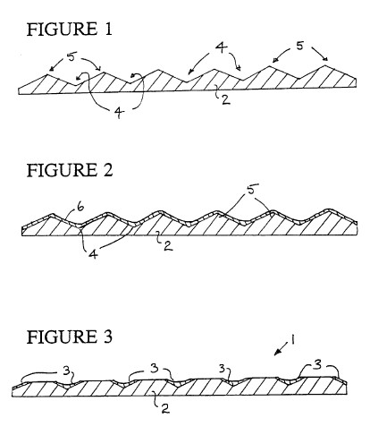
**BEST MODE FOR CARRYING OUT THE INVENTION**
A known electrolyte cell comprises an anode and a cathode as
electrodes in an aqueous solution of an electrolyte. If a
sufficiently large voltage, i.e. the "emf" of the cell, is
applied across the electrodes, gaseous products (hydrogen and
oxygen) are released at the electrodes. For any given
electrolyte in water, this value lie between 1.250 volts and
2.000 volts, depending upon the ambient conditions in the cell
(temperature, electrode metals, degree of wetting, pH of the
electrolyte etc.), and is known as the Decomposition Voltage or
DV. It is made up of three component voltages, which add
arithmetically to give the overall DV for the cell, namely: the
hydrogen over-voltage at the cathode; the oxygen over-voltage at
the anode; and the electrolyte breakdown voltage.
An electrolytic cell in accordance with the invention differs
from known electrolytic cells in that it functions as a
so-called Sub-Decomposition-Voltage (hereafter referred to as
"SDV") cell which is able to operate at voltages well below the
predicted emfs which would be expected by summing the three
component voltages above for any given set of cell
characteristics.
There are two principal parameters of an SDV electrolytic cell
which cause it to function in the way it does. The first
parameter is the nature of the electrolyte, and the second (more
important) is the physical characteristic of the cathodic
electrode. These two parameters are considered below.
**Electrolyte**
In common with nearly all electrolytic mechanisms, an SDV cell
will not work using pure water or even, to any great degree, tap
water as the electrolyte. The activity of electrolysis depends
upon the migration of ions towards charged surfaces, where they
act as either donors or recipients of electrons, and there are
simply not enough dissociated ions in pure water to enable this
to take place effectively. An electrolyte, as well as
dissociating into ions itself, will facilitate to a greater or
lesser degree the dissociation of the water in which it is
placed. The electolyte material is, nonetheless, recycled and
wholly conserved in the process and, once charged, an SDV cell,
in common with most other electrolysis devices, requires only to
be topped up with water, not fresh electrolyte. Examples of
electrolytes which have been successfully employed in SDV cells
include dilute H.sub.2 SO.sub.4, lithium sulphate monohydrate,
nickel sulphate hexahydrate, chromium sulphate, and palladous
chloride, although this is by no means an exhaustive list of the
possible substances. Those which function by the release of
SO.sub.4.sup.2- ions in solution seem also to perform better
when acidified slightly.
**The Nature of the Cathode**
The cathode of the SDV cell has an active surface comprising
two different metallic materials with a plurality of interfaces
between the different metallic materials. Conveniently the SDV
cathode 1 (see FIG. 3) consists of a substrate 2 of a first
metallic material and a plurality of isolated plated region 3 on
the substrate 2. Suitably the plated second metallic material
comprises nickel, or a matrix of nickel and chromium, so as to
create interfaces between the substrate and the plating.
At these interfaces in use of the SDV cell, a number of complex
electrochemical interactions take place. When a small voltage is
applied across the anode and cathode, H.sub.3 O+ (and other+ve)
ions are attracted towards the cathode. These ions are absorbed
into the crystal matrix of the nickel plated areas but not into
the areas of untreated steel. The sorption process takes place
in three main steps, namely: the surface adsorption of the ions,
accompanied by their partial dissociation into monatomic
hydrogen and water; followed by intergranular rift diffusion of
individual atoms of hydrogen between the nickel crystals; and,
lastly, lattice diffusion of the same hydrogen atoms from the
rifts into the actual lattice of the crystal structure. This is
not a clathrate process, there being an immediate association of
monatomic H into molecular H.sub.2 within the lattice,
accompanied by an increase in pressure. The rate-controlling
process is probably the surface adsorption as increased working
pressure within the cell appears to have little effect on the
rate of hydrogen take-up.
Lattice diffusion continues until the interface between nickel
and steel is encountered and it is at this point that molecular
hydrogen is released into the adjacent electrolyte. The entire
process maintains an equilibrium with the ion-product of the
water in the electrolyte, new H.sub.3 O+ and other ions being
formed at the same rate as molecular hydrogen is being
discharged from the cell. It is thought that there are two
catalytic, facilitating, reactions at work. Firstly, the
transition from integranular rift diffusion to lattice diffusion
is believed to be facilitated by the somewhat unbalanced nature
of the two outermost quantum groups in the nickel atom,
monatomic hydrogen being "ushered", as it were, by the weak
forces within the lattice itself. (Although nascent hydrogen is
not itself a polar entity, the existence within any mass of H of
two species, ortho- and para-, dependant on Pauli m.sub.s values
of + or -1/2, does not rule out some kind of interaction when
such a monatomic gas is confined within an electrostatically
active crystalline complex.) Secondly, at the small iron-nickel
interfaces which occur when the cathode is machined, there is a
degree of electron-sharing between adjacent iron and nickel
atoms at the periphery of the crystal structure which in some
way mitigates in favour of molecular H.sub.2. There are also
grounds for considering the existence of free protons within
such a intercrystalline confinement and there is nothing in the
electrochemistry which would rule this out.
**The Anode Process**
The anode process differs from that of a conventional cell in
that the oxygen over-voltage is rarely exceeded and the reaction
at the anode is one of the formation of a (conductive) layer of
a matrix of ferrous- and feroso-ferrous-oxide over the plain
steel electrode. There is some liberation, albeit slowly, of
gaseous oxygen at the anode but this is small in comparison with
the ejection of H.sub.2 from the cathode, which occurs
prolifically and often (as would be expected given the pressure
within the crystalline absorption mechanism at work) with some
minor violence when observed under the microscope.
There is, obviously, some likely benefit in obtaining hydrogen
from such a process which is relatively free of associated
oxygen but, to date, the gaseous mix from experimental SDV cells
has not been such as to bring the O.sub.2 level down below the
LEL for hydrogen/oxygen mixture, and such cells should not be
regarded as being intrinsically safer than conventional ones.
One method of creating an SDV electrode is described below.
The electrode which is to become the cathode in an SDV cell is
made by taking a sheet of ordinary mild steel as the substrate 2
and creating on its surface a series of irregularities, in the
form of trough regions 4 and raised regions 5 (see FIG. 1), by
etching the steel in a bath of concentrated (50-55%) sulphuric
acid. The natural impurity of most commonly available mild steel
ensures that etching will take place in a random and irregular
manner. Mostly, this is caused by the presence of finely divided
granular alpha-ferrite which appears to be preferentially
attacked by the acid.
After inspection of the surface and the determination of the
average size of the nodes or raised regions on the roughened
steel (optimally these should be at 0.03-0.05 mm distribution),
the surface is passivated in concentrated nitric acid and
further passivated in a chromic acid bath.
The roughened surface of the steel substrate 2 is then given a
25-micron coating 6 of nickel by the "electroless" process, also
known as auto-catalytic chemical deposition (see FIG. 2). This
plating process provides accretion of deposited nickel in the
trough regions 4 and thinner deposits of nickel on the raised
regions 5.
After coating, the electrode is machined or ground, e.g. using
a linishing sander and 120 grit silicon carbide paper belt, to
remove the "peaks" of the plated raised regions 5 and in
particular to remove the plated nickel from these "peaks" so as
to expose the steel of the substrate 2 (see FIG. 3). In this way
a plurality of metal-to-metal interfaces are created on the
active surface of the cathode between the nickel plated regions
on the trough regions 4 of the substrate 2 and the exposed steel
surfaces of the substrate. Constant microscopic inspection is
required to determine the existence of the correct bi-metallic
interfaces on the active surface of the electrode. If the
electrode is to be used with only one active surface (SAS
electrode), no treatment is given to the other plated surface,
which will remain electrochemically inactive during the
operation of the cell. If both surfaces are required to work
electrolytically (DAS), a similar treatment is given to the
other side. After cleaning the electrode in methyl ethyl ketone
to remove grease and other machining deposits, it is left
immersed in a 0.5N aqueous solution of nickel sulphate
hexahydrate at 55.degree. C. for 24 hours, which process acts as
an "initiator" for the later complex sequence of ion exchange
operations in the active cell.
The present invention envisages a novel cathode and SDV
electrolytic cell provided with such a cathode. The invention
also teaches a novel method of making such a cathode and a novel
method of releasing gaseous products from an SDV cell.
The invention discloses the provision of bi-metallic interfaces
on the active, electrolyte-contacting surface of an electrode
which produces hitherto unobserved electrochemical phenomena.
The use of dissimilar metallic materials on the active surface
facilitates lattice diffusion of gases within the crystal
structure of the electrode.
An SDV cell according to the invention acts as an "over-unity"
cell in respect of hydrogen gas production from the cell. The
cell operates at low voltages of no more than 1 volt, preferably
no more than 0.8 volt and typically from 0.2 to 0.6 volts.
However even lower operating voltages are feasible.
---
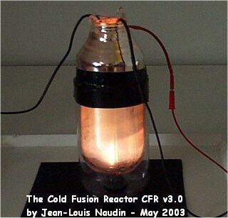
**JL Naudin Laboratory:
**
Video of Test Run # 1: ****
**"The Enhanced Cold Fusion Reactor v3.0"**
**Description**
The Cold Fusion Reactor ( CFR ) v3.0 uses a new enhanced design
with a 1000 mL Dewar vessel filled with a 600 mL of
demineralized water and 41.5 g of Potassium Carbonate, the
electrolyte solution used is 0.5 molar ( 0.5 M, ). The Dewar
vessel, used as the container for the CFR v3.0, keeps the strong
heat and the light energy produced by the reactor. The reduced
output of the Dewar neck avoid some eventual projections of the
water outside the vessel.
The CFR v3.0 runs at a very stable regime and the power
efficiency measured during all the tests conducted is more than
200%.
The Cathode used is a pure tungsten rod ( W ) 3 mm diameter and
25 mm length from tungsten TIG electrodes (WP) commonly used for
TIG and Plasma welding. The Anode used is composed of stainless
steel grid maintained with a stainless steel shaft. All
the wires connections are made with a 1.5 mm2 copper flexible
wire gained with silicon.
The CFR v3.0 is powered with a DC voltage through a bridge
rectifier connected through an adjustable isolation transformer
to the 220V AC power grid line. The voltage input has been
measured with a digital oscilloscope Fluke 123 with a Shielded
Test Lead STL 120 ( 1:1, 1 Mohms/225 pF ). The current input has
been measured with a current clamp CIE Model CA-60A ( Accuracy
DC Amps +/-1.5%, AC Amps +/-2% (40 Hz - 2 kHz), AC Amps +/-4% (2 kHz
-10 kHz), AC Amps +/-6% (10 kHz - 20kHz) ). The temperature has
been measured with a type "K" temp probe ( NiCrNi ) connected on
a VC506 digital multimeter ( -20 degC to +1200 degC with an accuracy
of +/- 3% ).
*Run # 1 ~ Test procedure :*
1) The temperature of the K2CO3 solution
in the CFR has been set initially to 83 degC.
2) The weight of the CFR has been measured initially, it was
1336 g.
3) The power supply has been switched on continuously and the
Voltage/Current datas has been recorded in the Fluke 123 digital
oscilloscope used as a data logger, up to a temperature of
102 degC.
4) Then the weight of the CFR has been measured, it was 1292 g.
The run time of the CFR has been 124.8 seconds.
The Voltage/Current datas logged give an average electrical
power input of 574.8 Watts during 124.8 seconds, so this gives :
ELECTRICAL ENERGY INPUT = 71739 Joules
The evaporated water in the CFR during the full boiling was 44
mL. We know that we need 2260 J/g to vaporize water. The
temperature rise of the 600 mL was 19 degC. So, this gives :
ENERGY OUTPUT = ( 44 x 2260 ) + ( 600 x 19 x 4.18 ) = 147092
Joules
Power OUTPUT = 1178.6 Watts, Net Power Gain = 603.8 Watts
Energy OUTPUT/INPUT = 147092 / 71739 = 2.05
*Run # 2 ~ Test procedure :*
1) The temperature of the K2CO3 solution
in the CFR has been set initially to 86 degC.
2) The weight of the CFR has been measured initially, it was
1334 g.
3) The power supply has been switched on continuously and the
Voltage/Current datas has been recorded in the Fluke 123 digital
oscilloscope used as a data logger, up to a temperature of
103 degC.
4) Then the weight of the CFR has been measured, it was 1286 g.
The run time of the CFR has been 127.2 seconds.
The Voltage/Current datas logged give an average electrical
power input of 518.2 Watts during 127.2 seconds, so this gives :
ELECTRICAL ENERGY INPUT = 65918 Joules
The evaporated water in the CFR during the full boiling was 48
mL. We know that we need 2260 J/g to vaporize water. The
temperature rise of the 600 mL was 17 degC. So, this gives :
ENERGY OUTPUT = ( 48 x 2260 ) + ( 600 x 17 x 4.18 ) = 151116
Joules
Power OUTPUT = 1188 Watts, Net Power Gain = 669.8 Watts
Energy OUTPUT/INPUT = 151116 / 65918 = 2.29
After a lot of tests runs, some small longitudinal cracks are
visible on the pure W cathode; these small fractures are
produced by the Hydrogen Embrittlement Cracking effect ( HEC )
on the tungsten.
Visit the Naudin Lab website for complete details...
---