Qiaoqiang GAN, et al. : Solar-Powered Still -- Carbon-soaked
paper & styrofoam design is 88% efficient, cheap, simple
**
[rexresearch.com](http://www.rexresearch.com/index.htm)**
---
**Qiaoqiang GAN*, et al.***
**Solar-Powered Still**
---
[**http://www.sciencedaily.com/releases/2019/08/190805112151.htm**](http://www.sciencedaily.com/releases/2019/08/190805112151.htm)**ScienceDaily, 5 August 2019****Nature Sustainability, 2019** **DOI: 10.1038/s41893-019-0348-5**
**A polydimethylsiloxane-coated metal
structure for all-day radiative cooling.** **Lyu Zhou, et al.**
*"In the future, this electricity-free
tech could help cool buildings in metropolitan areas."*
Engineers have designed a new system that can help cool
buildings in crowded metropolitan areas without consuming
electricity, an important innovation at a time when cities are
working to adapt to climate change.
The system consists of a special material -- an inexpensive
polymer/aluminum film -- that's installed inside a box at the
bottom of a specially designed solar "shelter." The film helps
to keep its surroundings cool by absorbing heat from the air
inside the box and transmitting that energy through the Earth's
atmosphere into outer space. The shelter serves a dual purpose,
helping to block incoming sunlight, while also beaming thermal
radiation emitted from the film into the sky.
"The polymer stays cool as it dissipates heat through thermal
radiation, and can then cool down the environment," says
co-first author Lyu Zhou, a PhD candidate in electrical
engineering in the University at Buffalo School of Engineering
and Applied Sciences. "This is called radiative or passive
cooling, and it's very interesting because it does not consume
electricity -- it won't need a battery or other electricity
source to realize cooling."
"One of the innovations of our system is the ability to
purposefully direct thermal emissions toward the sky," says lead
researcher Qiaoqiang Gan, PhD, UB associate professor of
electrical engineering. "Normally, thermal emissions travel in
all directions. We have found a way to beam the emissions in a
narrow direction. This enables the system to be more effective
in urban environments, where there are tall buildings on all
sides. We use low-cost, commercially available materials, and
find that they perform very well."
Taken together, the shelter-and-box system the engineers
designed measures about 18 inches tall (45.72 centimeters), 10
inches wide and 10 inches long (25.4 centimeters). To cool a
building, numerous units of the system would need to be
installed to cover a roof.
The research will be published on Aug. 5 in Nature
Sustainability. The study was an international collaboration
between Gan's group at UB, Boon Ooi's group at King Abdullah
University of Science and Technology (KAUST) in Saudi Arabia,
and Zongfu Yu's group at the University of Wisconsin-Madison.
Along with Zhou, co-first authors are Haomin Song, PhD, UB
assistant professor of research in electrical engineering, and
Jianwei Liang at KAUST. The study was funded in part by the
National Science Foundation.
**A system that works during the day and in crowded
environments**
The new passive cooling system addresses an important problem in
the field: How radiative cooling can work during the day and in
crowded urban areas.
"During the night, radiative cooling is easy because we don't
have solar input, so thermal emissions just go out and we
realize radiative cooling easily," Song says. "But daytime
cooling is a challenge because the sun is shining. In this
situation, you need to find strategies to prevent rooftops from
heating up. You also need to find emissive materials that don't
absorb solar energy. Our system address these challenges."
When placed outside during the day, the heat-emanating film and
solar shelter helped reduce the temperature of a small, enclosed
space by a maximum of about 6 degrees Celsius (11 degrees
Fahrenheit). At night, that figure rose to about 11 degrees
Celsius (about 20 degrees Fahrenheit).
**How innovative architecture can drive radiative cooling**
The new radiative cooling system incorporates a number of
optically interesting design features.
One of the central components is the polymer/metal film, which
is made from a sheet of aluminum coated with a clear polymer
called polydimethylsiloxane. The aluminum reflects sunlight,
while the polymer absorbs and dissipates heat from the
surrounding air. Engineers placed the material at the bottom of
a foam box and erected a solar "shelter" atop the box, using a
solar energy-absorbing material to construct four
outward-slanting walls, along with an inverted square cone
within those walls.
This architecture serves a dual purpose: First, it helps to
sponge up sunlight. Second, the shape of the walls and cone
direct heat emitted by the film toward the sky.
"If you look at the headlight of your car, it has a certain
structure that allows it to direct the light in a certain
direction," Gan says. "We follow this kind of a design. The
structure of our beam-shaping system increases our access to the
sky. The ability to direct the emissions improves the
performance of the system in crowded areas."
---
**WO2018102573**
**System and method for solar vapor evaporation and
condensation**
**[ [PDF](file:///C:/Users/Googool/Downloads/0gansolar/WO2018102573.pdf)
]**
Inventor(s): GAN QIAOQIANG; YU ZONGFU; LIU
ZHEJUN; SONG HAOMIN; SINGER MATTHEW; LI CHENYU +
Applicant(s): UNIV NEW YORK STATE RES FOUN
A solar vapor generator system and method are provided. In some
embodiments, the system has near perfect energy conversion
efficiency in the process of solar vapor generation below room
temperature. Remarkably, when the operation temperature of the
system is below that of the surroundings, the total vapor
generation will be higher than the upper limit that can be
produced by the input solar energy.
**Background of the Disclosure**
[0002] The advent of the steam engine was one of the key
developments that led to the first Industrial Revolution. Since
then, the use of steam has influenced many aspects of modern
life. For instance, thermal steam generation and condensation
was one of the dominant technologies for seawater desalination
before the introduction of reverse osmosis technologies.
Although membrane-based technologies became the dominant
solution to desalination, they are usually energetically
demanding with serious environmental impacts arising from
cleaning and maintenance. As a result, there is emerging global
interest in developing alternative desalination technologies to
address these issues. Solar vapor generation with no electrical
input is proving to be a promising and environmentally benign
solution, especially in resource limited areas.
However, conventional techniques for generating solar vapor
typically rely on costly and cumbersome optical concentration
systems to enable bulk heating of a liquid, resulting in
relatively low efficiencies (e.g., 30%-40%) due to heat
absorption throughout the entire liquid volume that is not
directly translated into vapor production. Recently, various
advanced and expensive metallic plasmonic and carbon-based
nanomaterials have been explored for use in solar vapor/steam
generation. However, the vaporization efficiencies of these
reported structures are still relatively low under 1 sun
illumination (e.g., 48% (10) ~ 83%). [0003] For practical
outdoor solar still applications, stable and continuous solar
illumination is not achievable in most areas of this planet due
to varying weather conditions. Even with inexpensive moderate
solar concentrators, a stable incident power higher than AM 1.5
solar light still cannot be guaranteed. Additionally, since most
solar stills are covered by glass or other similar collection
material, condensation can lead to optical scattering and a
decrease in the incident solar power. Therefore, vapor
generation under < 1 solar illumination condition is an
important, long-felt need, despite being neglected in most
previously reported work. Brief Summary of the Disclosure
[0004] The present disclosure provides an alternative approach
to solar vapor generation using a supported substrate. In an
extremely cost-efficient and effective embodiment, the substrate
is a carbon black-dyed cellulose-polyester blend (CCP) and the
support is expanded polystyrene foam (EPS). A system according
to some embodiments of the disclosed technology achieved a
record thermal conversion efficiency of -88% under
non-concentrated solar illumination of 1 kW/m<2>. This
corresponds to an optimized vapor generation rate that is ~3
times greater than that of natural evaporation. Stable and
repeated seawater desalination tests were performed in a
portable prototype both in the laboratory and an outdoor
environment, and achieved a water generation rate that was 2.4
times that of a commercial product. Also, desalination systems
according to some embodiments of the present disclosure largely
avoid the costs for seawater intake and pretreatment that are
generally required for conventional reverse osmosis processes.
Compared with previously reported advanced nanostructures, this
CP -EPS system is extremely low-cost in terms of both materials
and fabrication, environmentally benign, and safe to handle
during production. These attributes enable such a system to be
easily expanded to a large scale system. Furthermore,
embodiments of the present system may be used for simultaneous
fresh water generation and treatment from heavily contaminated
source water. Membrane filters and photocatalysts may also be
incorporated to purify contaminated source water. Considering
the challenges in contaminated/waste water treatment and reuse,
the development of low cost, electricity-free, and
multi-functional technologies represents a significant advance
in the field.
[0005] In some embodiments, the approach further utilizes cold
vapor below room temperature, and provides a near unity
conversion efficiency of absorbed solar energy. Due to the
energy contribution from the surroundings, the measured total
vapor generation is higher than the upper limit that can be
produced by a given incident solar energy. Importantly, this
breakthrough technique was realized using the extremely low cost
CCP-foam system under 1 sun illumination, with no need for
advanced and expensive nanomaterials. In addition, features for
optically absorbing and evaporative materials for solar still
systems are shown: i.e., under a given environment, a stronger
natural evaporation capability will result in a lower surface
temperature. This provides applications in solar still
technology, evaporative cooling and solar evaporated mining
applications, evaporation-driven generators and recently
reported water- evaporation-induced electricity. Description of
the Drawings
[0006] For a fuller understanding of the nature and objects of
the disclosure, reference should be made to the following
detailed description taken in conjunction with the accompanying
drawings, in which:
Figure 1 depicts the physical mechanism of vapor generation. (A)
Energy balance and heat transfer diagram of the CCP-foam under
strong solar illumination. The surface temperature, T2, is
higher than the room (ambient) temperature, Ti. (B) A photograph
of CCP-foam floating on top of water surface and its
corresponding thermal image under dark environmenta the surface
temperature is below room temperature. (C) Energy balance and
heat transfer diagram of the CCP-foam under dark environment or
low intensity illumination. (D) A photograph of a CCP-air
gap-foam structure floating on top of water and its
corresponding thermal image under dark environmenta the surface
temperature is even lower than the CCP-foam structure.
Figure 2 shows vapor generation under low density light
illumination. (A) Photographs of a CCP-foam (upper panel) and a
CCP-air gap-foam (lower panel) under 0.6 sun illumination.
(B) Thermal images of the CCP-foam (upper panel) and the CCP-air
gap- foam (lower panel) under 0.6 sun illumination. (C)
Comparison of measured water weight change versus time of
CCP-foam and CCP-air gap-foam. The upper limit that can be
produced by 0.6 sun input solar energy is plotted by the solid
curve. (D) Thermal images of the CCP-foam (upper panel) and the
CCP-air gap-foam (lower panel) under 0.2 sun illumination. (E)
Comparison of measured water weight change versus time of CCP-
foam and CCP-air gap-foam. The upper limit that can be produced
by 0.2 sun input solar energy is plotted by the solid curve.
Figure 3 shows the physical interpretation of energy balance of
solar vapor generation systems. (A) Energy flow diagram under
dark conditions: the input energy from the environment is in
balance with the evaporation energy. (B) Energy flow diagram of
a below-room-temperature system with a weak light input: the
output evaporation energy is the sum of the light input and the
environment input. (C) Energy flow diagram of a room-
temperature system: the output evaporation energy is in balance
with the surrounding and light input. (D) Energy flow diagram of
a hot system: the input solar energy is the sum of the
evaporation energy and the loss to the environment. Figure 4A
and 4B show the increased surface area under 1 sun illumination.
(4A(A))
Exemplary schematic diagram to reduce the light density by
introducing larger surface area structures. (4A(B), 4A(D)-4A(E))
Thermal distribution images and corresponding photographs of
three exemplary samples (4A(B)) a flat CCP -foam, (4A(D)) a
triangle structure with T of 37.8, (4A(E)) a triangle
structure with T of 22.9. (4B(C)) Comparison of
measured water weight change versus time of the three exemplary
CCP-foam samples (spheres)a wherein the calculated upper limits
that can be produced by 1 sun input solar energy are plotted by
solid curves. (4A(F)-4A(G)) The thermal distribution images and
corresponding photographs of CCP-air gap-foam structures with
(4A(F)) T =37.4and (4A(G)) T =22.4. (4B(H))
Comparison of measured water weight change versus time of these
two CCP-air gap-foam samples (spheres)a wherein the calculated
upper limits that can be produced by 1 sun input solar energy
are plotted by solid curves.
Figure 5 A shows the configuration of a water diffusion height
experiment for three sample substrates: white substrate (left);
CCP (center); sodium alginate treated CCP (right). Figure 5B is
a thermal image of the three sample substrates of Figure 5 A
showing the resulting water diffusion heights.
Figure 6 shows the optical absorption spectrum of the CCP and
the transmission spectrum of the diffuser. The absorption is
-96.9% by weighting absorption spectrum (topmost curve) with the
AM 1.5 solar irradiance, which contributes to a high efficiency.
The shaded area shows the solar irradiation spectrum as a
reference. The transmission spectrum (middle curve) indicates
that the transmitted light by the diffuser will basically keep
the energy distribution of AM 1.5 at different wavelengths.
Figure 7 shows an experimental setup for solar vapor generation.
CCP-foam is illuminated using the solar simulator.
Figure 8 shows an apparatus used to characterize dark
evaporation in controlled environment (a commercial glove box is
61 cm x 46 cm x 38 cm with controlled relative humidity and
temperature inside the box).
Figure 9 is an illustration of an embodiment of a solar
evaporator module floating on top of water surface, wherein each
module contains an electricity/solar-driven fan to accelerate
the convection.
Figure 10 shows an embodiment of the presently-disclosed carbon
substrate in a NaCl brine under 1 sun illumination with a
picture being recorded every 30 minutes. One can see the salt
crystal accumulated on top of the black substrate surface, which
will decrease the vapor evaporation rate. Intriguingly, the salt
crystals tended to accumulate on the substrate surface (up to
image 10), which may simplify the collection of salt in
practice.
Figure 11 shows the mass change over time of the sample under 1
sun illumination. Notice that as salt builds up on our material,
only a slight decrease in performance is observed (up to image
10). Therefore, the performance of the salt collector should be
very stable and can be replaced easily. Moreover, when the solar
simulator is turned off after 8-hour illumination, the salt will
be dissolved from the CCP surface back into the bulk water,
demonstrating the minimum maintenance requirements.
Figures 12A and 12B show a preliminary experiment in an outdoor
environment. Each container has 450 ml water with 40 gram salt.
After 10 hour test (Figure 12B), obvious salt can be obtained
from the carbon substrate surface (left container) while the
control sample did not have any output (right container).
Therefore, the presently-disclosed strategy can be used for a
solar mining using low concentration solution. At least 8 grams
of salt were obtained from the carbon substrate surface in the
experiment.
Figure 13 depicts a system according to another embodiment of
the present disclosure.
Figure 14 (A) Scanning Electron Microscope (SEM) image of
uncoated fiber-rich paper.
(B) SEM image of CCP under low and high magnifications (inset).
(C) Top line:
Absorption spectra of uncoated white paper; Bottom line:
Absorption spectra of CCP. Absorption spectra were measured by
an integration sphere; Inset: Photograph of these two pieces of
paper. (D) Comparison of water weight change versus time under
four different conditions: i) water in dark environment; ii)
water under 1 kW/m<2>illumination; iii) floating white
paper under 1 kW/m<2>illumination and iv) floating CCP
under 1 kW/m<2>illumination. (E) The surface temperature
distribution of the four samples measured in Figure 14(D)
measured using a thermal imager: the upper left panel
corresponds to i) of Figure 14(D); the upper right panel
corresponds to ii) of Figure 14(D); the lower left panel
corresponds to iii) of Figure 14(D) and the lower right panel
corresponds to iv) of Figure 14(D).
Figure 15A Photographs of a CCP with (upper panel) and without
the insulating EPS foam (lower panel) floating on top of water.
Figure 15B Photograph of the CCP-foam structure with cover foam
to eliminate evaporation from the water surface surrounding the
CCP-foam structure. Figure 15C Comparison of water mass change
due to evaporation versus time under four different conditions:
water under 1 kW/m<2>, exfoliated graphite on foam from
previous work, CCP without insulating foam, and CCP with
insulating foam.
Figure 15D Surface temperature distribution of an exemplary CCP
with (upper panel) and without the insulating EPS foam (lower
panel) floating on the water.
Figure 16 (A) The water mass change as a function of time under
1, 3, 5, 7 and 10 times concentrated solar illumination,
respectively. (B) The temperature change as a function of time
under 1, 3, 5, 7 and 10 times concentrated solar illumination,
respectively. The solid lines represent vapor temperatures
measured by a thermometer installed above the CCP- foam. The
dashed lines represent bulk water temperatures measured under
the foam, while the lines are as for Figure 16(A). (C) The solar
thermal conversion efficiency (light gray dots) and
corresponding evaporation rate (black dots) as a function of
solar intensity. (D) Direct comparison of solar thermal
conversion efficiencies obtained by previously reported
structures and an exemplary CCP-foam according to an embodiment
of the present disclosure.
Figure 17 (A) Energy balance and heat transfer diagram in an
exemplary CCP-foam architecture during the vapor generation
process. (B) Diagram of the detail near the surface of the CCP
structure during the vapor generation process.
Figure 18 (A) Evaporation rate of exemplary CCP-foam samples on
salt water and pure water as the function of cycle number. The
two solid lines are reference lines to show the stable
performance. (B) An SEM image of an exemplary CCP sample after 1
hour evaporation in salt water. (C) Evaporation rate of CCP
sample in salt water over an 8- hour evaporation period as a
function of illumination time. (D) Photographs and (E) thermal
images of an exemplary CCP-foam on salt water at times
corresponding to the evaporation rate of salt water in Figure
17(C).
Figure 19A (A) Schematic illustration of a conventional
desalination solar still. (B)
Photograph of a 5x5 CCP array with a total area of 100
cm<2>according to an embodiment of the present disclosure.
(C) and (D) are thermal images of the CCP array before (C) and
after (D) solar illumination. (E-G) Photographs of experimental
systems with (E) a CCP- foam array on salt water, (F) bare salt
water with a layer of black aluminum foil placed at the bottom,
and (G) bare salt water with no CCP-foam. (I) The photograph of
a prototype system placed outdoors on a lake. (J) The photograph
of a control experiment with a commercial product (left) and the
exemplary system (right) during the experiment.
Condensation can be seen at the inner surfaces of the covers.
Figure 19B (H) Hourly water weight change with the exemplary
CCP-foam array on the water surface (dots), black aluminum foil
at the bottom (triangles), and salt water (squares) as a
function of illumination time; the top dashed line is the hourly
bulk water temperature under CCP foam; middle dashed line is the
hourly bulk water temperature with the black aluminum foil at
the bottom of the container; bottom dashed line is the hourly
water weight change of salt water. (K) The solar intensity
(upper panel) and outdoor temperature curves (lower panel) from
8:00 am to 6:00 pm on May 6, 2016. Figure 20 (A) Comparison of
the water solution used to ultrasonically clean a CCP sample
after different amounts of time. (B) Photographs of the CCP
sample after different amounts of ultrasonic cleaning time. (C)
Optical absorption spectra of the CCP sample after ultrasonic
cleaning.
Figure 21 (A) Surface temperature distribution of a black Al
foil (left) and a CCP sample (right) placed on top of a heat
plate set at 40 A degC. (B) Direct measurement of the temperature at
three positions using a thermal couple sensor probe.
Figure 22 Photographs of an experimental setup to measure the
temperature of (A) vapor and (B) bulk water.
Figure 23 Optical absorption spectrum of a black Al foil
measured by an integration sphere.
Inset: the photograph of a black Al foil.
Figure 24 is a diagram depicting another embodiment of the
present disclosure.
Figure 25 is a diagram depicting another embodiment of the
present disclosure.
Figure 26A is a side view of an exemplary solar still according
to an embodiment of the present disclosure.
Figure 26B is a top view diagram of the solar still of Figure
26A.
Figure 26C is a photograph of the exemplary solar still
constructed according to Figures 26A and 26B.
Figure 27 is a diagram of an exemplary floating CCP-foam with
air gap for thermal isolation (side view).
Figure 28 is a chart depicting another embodiment of the present
disclosure. Detailed Description of the Disclosure
[0007] Unless defined otherwise herein, all technical and
scientific terms used in this disclosure have the same meaning
as commonly understood by one of ordinary skill in the art to
which this disclosure pertains. The disclosure includes all
combinations of all components and steps described herein.
Throughout this application, the singular form includes the
plural form and vice versa.
[0008] By utilizing extremely low-cost materials in this
invention, economically viable large-area systems are now
possible with no energy input required for operation. This
prospect is particularly attractive for addressing global
freshwater shortages, especially for individuals to purify water
for personal needs (i.e., ~2 liter/day) in developing regions.
Because embodiments of the present disclosure do require special
micro/nanofabrication processes and do not require solar
concentrators, the disclosed technology is extremely low-cost
and amenable to scaling up over large or huge areas for real
applications.
[0009] Without being bound by any theory, due to the superior
absorption, heat conversion, and insulating properties of the
presently-disclosed CCP-foam structure, most of the absorbed
energy can be used to evaporate surface water with significantly
reduced thermal dissipation compared with previously reported
architectures. Without being bound by any theory, due to the
thermal insulation between the surface liquid and the bulk
volume of the water and the suppressed radiative and convective
losses from the absorber surface to the adjacent heated vapor, a
record solar thermal conversion efficiency of > 88% under
illumination of 1 kW/m<2>(corresponding to the evaporation
rate of 1.28 kg/(m<2>h)) was realized using an embodiment
of the disclosure having no solar concentration. When scaled up
to a 100 cm<2>array in a portable solar water still
system, the outdoor fresh water generation rate was 2.4 times of
that of a leading commercial product. Furthermore, seawater
desalination was also demonstrated with reusable stable
performance.
[0010] To enhance the vapor generation rate, typically the
approach is to increase the operation temperature for a given
solar illumination. However, this will inevitably increase the
thermal loss to the surroundings mainly via conduction,
convection and radiation losses.
Therefore, high temperature solar vapor generation (e.g., with
solar concentration) inherently suffers from limits in energy
conversion efficiencies. [0011] In some embodiments, present
disclosure provides techniques which take an opposite approach,
using solar energy to generate cold vapor below room
temperature, to provide surprising results. This is a
breakthrough pathway for efficient solar vapor generation since
under illumination at low power densities, the
absorbed-light-to-vapor energy conversion efficiency can reach
-100% when the evaporation temperature is lower than the room
temperature. Under this condition, the environment will provide
additional energy for vapor generation, resulting in a total
vaporization rate that is higher than the upper limit that can
be produced using the input solar energy alone. This cold vapor
generation technique was experimentally validated and
demonstrated limit-breaking vaporization rates using an
extremely low cost CCP-foam system.
[0012] With reference to Figure 13, in a first aspect, the
present disclosure may be embodied as a solar vapor generation
system 10 having an open-topped vessel 12 for holding a
solution, for example, a water-based solution. A substrate 20 is
configured to be placed in the open-topped vessel 20. The
substrate 20 is configured to wick solution from the vessel 12.
The substrate 20 may be supported near an exposed surface of the
solution (i.e., near the top of the open-topped vessel 12) by a
support 22. The support may have a density less than water. The
support 22 may be thermally insulative and/or thermally stable.
The support 22 may be a foam. The support 22 may be configured
to not absorb water. The support 22 may comprise expanded
polystyrene foam (EPS), polyurethane foam, polyvinyl chloride
foam, polyethylene form, a phenol formaldehyde resin foam, or
other foam materials or combinations of one or more materials.
The support 22 may include an air gap, to separate at least a
portion of the substrate 20 from the support 22 allowing air to
pass between a portion of the support 22 and the substrate 20
(see, e.g., Figure 27).
[0013] The system 10 may further comprise a housing 14. The
substrate 20 and the support 22 may be located within the
housing 14. In some embodiments, at least a portion of the
vessel 12 may be located within the housing 14. The housing 14
may be configured so as to admit solar energy. For example, the
housing 14 may have a transparent top. For example, the housing
14, or a portion thereof, may be made from a transparent
plastic, a transparent glass, a transparent polymer membrane
(e.g., microwave membrane), etc. In some embodiments, an
interior surface of the cover is coated with a non-toxic,
anti-mist super-hydrophobic surface treatment. [0014] The system
10 may further comprise an air mover 30 configured to cause air
(e.g., ambient air) to move adjacent to the substrate 20. The
air mover 30 may be an electrically- powered fan 30, which may
be powered by way of, for example, a solar cell 32.
[0015] In some embodiments, a temperature of the substrate 20 is
maintained substantially at or below an ambient temperature. For
example, in embodiments having a housing 14, the housing may be
a temperature-controlled housing 14 for maintaining an ambient
temperature above the temperature of the substrate 20. By
maintaining a temperature substantially at an ambient
temperature, it is intended that the temperature of the
substrate be maintained to within 5 A degC of the ambient
temperature. In some embodiments, substantially at the ambient
temperature means to maintain the temperature to within 1, 2, 3,
or 4 A degC or any other value therebetween to within a decimal
position. In some embodiments, the substrate is maintained at a
temperature below the ambient temperature.
[0016] In some embodiments, the system 10 is used as a solar
still. For example, in such embodiments, the system 10 may be
used to desalinate water for use as drinking water. In such
embodiments, the system 10 may further comprise a condenser for
condensing the generated vapor. For example, the housing 14 may
be configured such that vapor condenses on the housing 14 (i.e.,
an inner surface of the housing) for recovery of the condensate.
In other embodiments, a condenser, such as a condensation trap,
may be located within the housing or outside of the housing.
[0017] As will be further described below under the heading
"Further Discussion," the substrate 20 may be configured as a
planar sheet generally parallel to a top surface of the
solution. In another embodiment, the substrate is tent-shaped,
comprising two planar sheets connected to one another along an
adjoining edge. The two planar sheets of a tent-shaped substrate
may connect at any angle, for example, at an angle of between
1.0 and 180.0 degrees, all values and ranges therebetween to the
first decimal place (tenths). In some embodiments, the two
planar sheets connect at an angle of between 20.0 and 45.0
degrees, inclusive and all values and ranges therebetween to the
first decimal place (tenths).
[0018] The substrate may be a porous material, such as, for
example, a fabric. The substrate may comprise paper and/or
plastic, for example, a porous fabric material comprising paper
and/or plastic. In some embodiments, the substrate is a
hydroentangled, non-woven 55% cellulose / 45% polyester blend,
such as TechniClothacent Wiper TX609, available from Texwipe. The
word "paper" does not signify, expressly or implicitly, any
equivalence between the "paper" used in some embodiments of the
subject disclosure and alternative paper material including any
prior substrate which may have been called "paper," but which
may have a different or unknown composition or arrangement of
fibers. The material may comprise material or material(s)
suitable for the purposes of the present substrate as will be
apparent in light of the present disclosure.
[0019] In some embodiments, the substrate comprises a
cellulose/polyester blend. The blend may comprise about 35% to
about 75% cellulose, including all integers and ranges
therebetween, and about 45% to about 65% polyester, including
all integers and ranges therebetween. In an embodiment, the
blend may comprise about 55% cellulose and about 45% polyester.
In another embodiment, the substrate may consist essentially of
cellulose, while in a different embodiments, the substrate does
not consist essentially of cellulose.
[0020] In some embodiments, the substrate is made from non-woven
fibers. In other embodiments, the substrate is made from woven
fibers (e.g., yarns). In other embodiments, the substrate is a
composite material. For example, the substrate may be made from
one or more non-woven layers and/or one or more woven layers. In
another example of a composite, the substrate may be made from
more than one layer, each layer made from the same or different
materials. Plastic or paper filter (virgin kraft paper) may also
be used as the substrate. In a further embodiment, the substrate
does not consist essentially of any one of the following: coral
fleece fabric, cotton, wool, nylon, jute cloth, coir mate or
polystyrene sponge.
[0021] In some embodiments, the substrate has a dark hue au
naturale. In some embodiments, the substrate is coated, dyed, or
otherwise colored to attain a dark hue. In some embodiments, the
substrate is black or substantially black. For example, the
substrate may be coated, dyed, or otherwise colored with carbon
black. In some embodiments, the carbon black comprises
nanoporous carbon black, microporous carbon black, or a mixture
thereof. In another embodiment, the carbon black consists
essentially of nanoporous carbon black. Selecting carbon black
of a particular sized porosity may be helpful in cleaning
contaminated water. However, it is not necessary for the
distillation of water, in which general purpose black carbon may
be used. Other black or dark pigments may also be used to dye or
coat the substrate.
[0022] In some embodiments, the substrate may have a length of
about 8 cm to about 14 cm and all integers and ranges
therebetween. The length was determined by the water
transportation capability of the substrate. The exemplary length
of about 10 cm to about 14 cm was used in an exemplary
embodiment for a hydroentangled (non-woven) substrate consisting
of about 55% cellulose and about 45% polyester. The width may be
greater for more substrates with greater liquid transport
potential. The length may be less than 10 cm or greater than 14
cm according to the application at hand. [0023] In some
embodiments, the substrate may have a width of about 8 cm to
about 14 cm and all integers and ranges therebetween. The width
was determined by the water
transportation capability of the substrate. The exemplary width
of about 8 cm to about 14 cm was used with a hydroentangled
(non-woven) substrate consisting of about 55% cellulose and
about 45% polyester. The width may be greater for more
substrates with greater liquid transport potential. The width
may be less than 8 cm or greater than 14 cm according to the
application at hand.
[0024] In some embodiments, the substrate has the shape of a
cross. In some embodiments, the substrate has the shape of a
square or rectangle. The substrate may be any shape suitable to
the application. [0025] In some embodiments, the substrate is
corrugated, in whole or in part (see, e.g.,
Figure 27). For the corrugation, smaller angles with straight
and sharp angle tips may be advantageous. Considering the moving
sun light, using corrugation having a smaller depth may be
better because using a large depth may cause a shadow effect
whereby some substrate will be shielded from light. An upper
limit of the corrugation depth may be selected such that the
solution can be transported to the entire surface of the
substrate. Corrugation not only significantly increases the
surface area, but also maintains the evaporated vapor at a
relatively low temperature so that energy loss to heat the water
and vapor can be suppressed, without being bound by any theory.
[0026] In some embodiments, the substrate and its support float
at the surface of the solution. For example, the solution may be
source water to be distilled. In such embodiments, where the
substrate and its support float on the source water, the
dimensions of the support and of the substrate may be selected
so that the ends of the substrate overlap the edges of the
support and contact the source water as shown in Figure 2 A.
[0027] In some embodiments, the support has a length of about 8
to about 10 cm. In some embodiments, the support has a width of
about 8 to about 10 cm. The support has a height of about 8 to
about 14 cm. The height can be greater for more absorbent
substrates or substrates with enhanced liquid transport
(wicking) capability. As before, these dimensions were optimized
for a hydroentangled (non-woven) substrate consisting of about
55% cellulose and about 45% polyester. The dimensions of the
support and of the substrate may be selected so that the ends of
the substrate overlap the edges of the support as shown in
Figure 2A. Other support sizes may be used and the above are
merely exemplary dimensions used to illustrate the present
disclosure.
[0028] Figure 24 depicts a solar vapor evaporation and
condensation system 100 according to another embodiment of the
present disclosure. A water source 104 is configured to provide
a supply of water to an open-topped vessel 112. For example, the
water source 104 may be higher than the vessel 112 such that
water flows by gravity. In some embodiments, the water source
104 may be a dark in colora for example, blacka so that the
contained water may be heated via solar heating. The system 100
may include a valve 106 configured to regulate the flow of water
from the water source 104. The valve 106 may be any suitable
type of valve, such as a manually-controlled valve. In some
embodiments, the valve 106 may be controlled automatically, for
example, based on a water level in the vessel 112. The vessel
112 may be thermally isolative. For example, the vessel 112 may
have a double-walled construction. Other thermally isolative
configurations will be apparent to the skilled person in light
of the present disclosure.
[0029] A support 122 is disposed within the vessel 112, and a
substrate 120 is disposed on the support 122. As described
above, the support 122 may be made from any suitable material,
such as, for example, EPS foam. Also as described above, the
substrate 120 may be made from a suitable wicking material, such
as, for example, CCP. Other materials may be used for the
support 122 and/or the substrate 120. The some embodiments, the
support 122 is configured to float on water contained within the
vessel 112. The substrate 120 may be configured to wick water
contained within the vessel 112. The system 100 may include a
solar concentrator 130a such as, for example, a Fresnel lensa
for increasing the solar energy directed towards the substrate
120.
[0030] The system 100 further includes a housing 140, which may
be in the shape of a cone, a dome, a pyramid, or any other shape
suitable to the purpose as is described herein. The housing 140
is arranged to contain the vessel 112 within. In this way, water
vapor evaporating from the water in the vessel 112 will condense
on an inner surface of the housing 140 and run down the inner
surface for collection in a collection container 150. The
collection container 150 may be constructed so as to encourage
condensation. For example, the collection container 150 may be
constructed using a single-layer of material, such as a plastic
or metal material. The system 100 may further include an outlet
152 whereby condensate (distillate) may be accessed for further
use/storage.
[0031] In another embodiment, a system 200 is configured to be
used in a body of water 290 (see, e.g., Figure 25). For example,
the system 200 may be designed to float in a body of water 290,
such as, for example, a lake, pond, river, man-made pools, etc.
A substrate 220 is disposed on a support 222, and configured to
wick water from the body of water 290 (e.g., the substrate 220
may overlap the support 222 and contact the water). The
substrate 220 and support 222 may be CCP-EPS foam, or other
suitable materials as further described in this disclosure. A
housing 240 is configured to contain the substrate 220 and
support 222. The housing 240 is arranged such that water vapor
evaporated from the substrate 220 is contained within the
housing 240 and caused to condense on an inner surface of the
housing 240. The housing 240 includes a collection channel 242
arranged to collect condensate which forms on the inner surface
of the housing 240. In this way, the condensate will run down
the inner surface of the housing 240 into the collection channel
242 where it is collected for use/storage. In some embodiments,
the collection channel 242 or a portion thereof is
advantageously arranged to be disposed within the bulk water 290
such that the bulk water cools the collection channel 242.
[0032] In some embodiments, the support includes an air gap 323
between a portion of the substrate 320 and a portion of the
support 322 (see, e.g., Figure 27). Such an air gap may serve as
a thermal isolator to minimize thermal dissipation into the bulk
water.
[0033] In another aspect, the present disclosure may be embodied
as a method 400 for solar vapor generation including placing a
solution, such as a water-based solution in an open- topped
vessel (see, e.g., Figure 28). A substrate may be disposed 403
in and/or on the solution. The substrate may be configured in
any way described herein. The substrate may be disposed 403 on
the solution using a support, such as a foam support, to float
the substrate at or near a top surface of the solution. The
substrate is exposed 406 to solar energy thereby causing
evaporation of the solvent (e.g., water), or increasing the rate
of evaporation of the solvent over the rate at which evaporation
would occur without a substrate and/or exposure to solar energy.
The method 400 includes maintaining 409 the substrate at a
temperature which is below the ambient temperature. The method
may include moving air adjacent to the substrate to further
increase the rate of evaporation and/or cool the substrate.
[0034] Some embodiments include chemically treating the
substrate and/or the carbon to be more hydrophilic. In some
embodiments, the substrate and/or the carbon is treated with
sodium alginate.
[0035] As previously mentioned, in some embodiments, the subject
invention provides methods and systems for solar distillation of
water comprising a substrate on a support. The substrate may be
referred to herein as a wick.
[0036] The sides, base, distillate channel, and collection
container may each independently comprise metal, plastic or
wood. The plastic may be acrylic. For the base, plastic or metal
are preferred.
[0037] Optionally, foam or other material less dense than water
may be added to ensure that the system floats (see, e.g., Figure
19A(I)). For example, a foam ring or open square may be attached
to the lower sides of the system. [0038] In an alternative
embodiment, at least an interior surface of the base may angled
so that the substrate and its support are angled to face the
sun.
[0039] Some embodiments of the presently-disclosed techniques
are particularly advantageous for use in mining applications,
and more particularly, in salt mining applications. Solar salt
mining is a common practice to obtain a plethora of different
salts ranging from table salt, NaCl, to Lithium-based salts
(e.g., Lithium Carbonate, Lithium Hydroxide, Lithium Chloride,
etc.), and Sodium/Potassium/Iodine salts for battery, food, and
medical applications. While salt processing plants have the
ability to process large amounts of raw salt product every year,
these plants rarely run at full capacity due to bottlenecks in
the production of raw salts from solar evaporation of salt
brine. Using embodiments of the present disclosure, the solar
evaporation of salt brines can be increased by 3-5x times the
natural rate. A low cost carbon nanomaterial based substrate was
developed and shown to be >88% efficient at converting solar
light into heat (see below under the heading "CCP Discussion and
Experimental Details"). This carbon substrate can easily be
applied using a roll-to-roll process for extremely feasible
scalability and modular systems, allowing the continued use of
the existing infrastructure for solar evaporation ponds while
providing greatly improved solutions to enhance salt production.
To further maintain current infrastructure, the material used
may be mechanically stable, thereby allowing the continued use
of current collection vehicles to drive over and scoop up the
raw salts. In addition to being low cost and scalable, the
present carbon-based substrate is chemically inert as to prevent
contamination and preserve purity of salt products.
[0040] In another aspect suitable for use in mining
applications, the present disclosure may be embodied as an
apparatus for improved salt separation in an evaporation pond.
The apparatus is similar to the above-described system where the
open-topped vessel is a pre-existing evaporation pond. As such,
the apparatus includes a substrate configured to wick solution
from the evaporation pond. The apparatus may include a support,
configured to support the substrate at a position near the
surface of the solution. A temperature of the substrate is
maintained below an ambient temperature. The substrate of such
an apparatus may be of any type described herein and may be
configured as a planar sheet or a tent-shaped configuration as
described herein.
[0041] In some embodiments, the substrate is configured in a
geometric shapea i.e., having a geometric circumferential shape.
In a particular example (illustrated in Figure 8), the substrate
is hexagonally shaped such that a plurality of substrates may be
arrayed to cover a large area. Other shapes and array
configurations will be apparent in light of the present
disclosure and are within the scope of the disclosure.
[0042] The substrate may configured for mechanical separation of
the salt. For example, the substrate may be a durable material
capable of withstanding mechanical separation (scraping,
beating, etc.) As such, the substrate may be reusable, such that
once the salts have been removed (substantially removed), the
substrate may be used to obtain salts again. In some
embodiments, the substrate is washable. Here again, such ability
to be washed allows for re-use of the substrate.
[0043] While solar salt mining focuses on the evaporation of
brine water to collect the salts left behind, embodiments of the
present system will also enable reclamation of the evaporated
water in a condenser unit. In this way, miners and staff may be
provided with a fresh supply of drinking water. This means for
no additional energy input, other than the natural solar
radiation, raw salt production can be enhanced 3-5x while saving
time, money, and other resources associated with providing these
often remote mining locations with clean drinking water. [0044]
In addition, the CCP structure can also be applied to
evaporation enhancement for water having only a low
concentration of salt. In such applications, accumulated salt
can re- dissolve into the water solution, providing a
"self-cleaning" feature and reducing the maintenance required
for operation. Additionally, Figure 10 shows a test embodiment
wherein salt tended to accumulate on the surface of the
substrate. This tendency may provide an advantage in collecting
the accumulated salt. For example, mechanical separation of the
salt from the substrate may be easier if the majority of
accumulated salt is on a surface of the substrate.
[0045] Additionally, the presently-disclosed process includes
the geometric assembly of the substrate. Based on geometry, the
carbon substrate can be arranged to induce higher airflow speed
which increases evaporation rates, prevents adsorption of salts
onto the surface of the substrate and easily transfers salts to
different collection containers, which aids in overall
collection and ease of use/maintenance. As such, the apparatus
for salt separation may include one or more air movers (for
example, as shown in Figure 8).
[0046] In contrast to water purification applications, solar
mining may utilize extra components/devices to accelerate the
vapor generation rate. For instance, electricity driven or solar
driven fans can be employed in the solar vapor generation for
salt mining. According to preliminary experiment results, an air
flow from 0.4 to 2 m/s can enhance the vapor generation rate by
1000% (dark environment) ~ 15% (under 3X sun illumination). In
particular, solar driven fans can be included in each solar
evaporator model (Figure 8). In addition, large scale fans can
also be installed at the edge of the pond.
**Further Discussion**
Loss channels in solar vapor generation systems and the strategy
to realize the perfect efficiency
[0047] As illustrated in Figure 1 A, major loss channels include
net radiation, convection and conduction losses. Therefore, the
power flux exchanged with the environment in the solar vapor
generation process can be described as:
P = Coptqi - es(7/2<4>- 7\<4>) - h T2- - qwater(1)
[0048] Here, a is the optical absorption coefficient, Copt is
the optical concentration, qi the normal direct solar
irradiation (i.e., 1 kW/m<2>for 1 sun at AM 1.5), e the
optical emission, s the Stefan-Boltzmann constant (i.e., 5.67x
10<"8>W/(m<2>-K<4>)), T2 the temperature at
the surface of the evaporative material, Ti the temperature of
the adjacent environment, h the convection heat transfer
coefficient, and qwater the heat flux to the bulk water. This
equation describes most major processes (if not all) involved in
the evaporation process, i.e., the absorption of light, aCoptqi,
the net radiative loss to the surroundings, es(?<4>2- ??),
the convective loss to the ambient, h(T2 - Ti), and the
radiative and conductive loss to the bulk water, qwater. By
manipulating the energy distribution among these channels,
unique solar vapor generation mechanisms can be realized. For
instance, a selective absorber and a bubble wrap cover can be
introduced to decrease the infrared thermal radiation (e) and
the convective loss (h) to the surroundings, respectively, to
produce 100 A degC steam under one sun illumination. However, for
high temperature solar vapor generation systems, these losses
can only be reduced but not eliminated completely. An important
question is what happens when T2= Ttl In this steady case (with
a stable surface temperature), the system will actually take
energy from the environment and the absorbed solar energy can
only be consumed in the liquid-to-vapor phase transition,
corresponding to near perfect solar energy conversion. Next, a
thermally isolated CCP on foam was employed as a low- cost test
bed to analyze the energy balance and heat transfers under both
dark and illuminated conditions.
**Experimental embodiments and results**
Materials [0049] In an exemplary embodiment, a substrate of
carbon-coated cellulose and polyester blend (CCP) was fabricated
using commercially available materials: paper (Texwipeacent TX609)
and carbon powder (Sid Richardson Carbon & Energy Company).
In some embodiments, evaporation performance can be further
manipulated by engineering features of carbon nanomaterial s.
For example, the light-absorbing substrate can be enhanced with
hydrophilic features. In particular, it may be advantageous to
provide a substrate that comprises a black material able to
absorb water and sunlight simultaneously and evaporate moisture
at a higher rate. To improve these characteristics, the porosity
of a carbon nanomaterial may be manipulated in some embodiments.
In some embodiments, the substrate and/or the carbon may be
chemically treated to increase hydrophilicity. In some
embodiments, the substrate and/or the carbon may be treated with
sodium alginate. [0050] In an experiment to demonstrate such
features, water diffusion height was employed as the figure of
merit to evaluate the absorptivity of materials under test
(Figure 5A). In the experiment, water diffusion height was
measured in substrates made from three sample materials: a first
sample comprising a white substrate (left sample); a second
sample comprising a substrate coated with a carbon nanomaterial
(center sample); and a third sample comprising a carbon-coated
substrate similar to the second sample and further treated with
sodium alginate (right sample). As shown by the infrared imaging
in Figure 5B, the water diffusion height of the first sample was
approximately 23 cm. In the second sample, water diffusion
height was approximately 37 cm, demonstrating improved water
absorptivity in the CCP material. In the third sample, the
hydrophilicity of the sample was improved by the sodium
alginate, resulting in a water diffusion height of approximately
43 cm.
**Methods****Sample fabrication**
[0051] 2 g carbon powder was dispersed into 400 mL water. 8 mL
acetic acid was added to make carbon powder easier to attach to
fibers. The solution was mixed in a 1000 ml beaker and blended
well using an ultrasonic cleaner (Branson Ultrasonics BransonicA(r)
B200) for 5 minutes. Subsequently, the prepared white substrate
was put into the mixed solution to vibrate and stir for 3
minutes so that carbon powders can dye the substrate uniformly.
After that, the CCP was dried at 80 A degC on a heating stage. This
procedure was repeated three to four times to realize a desired
dark color.
**Sample characterization**
[0052] The absorption spectrum using an integration sphere
spectroscopy (Thorlabs IS200-4 integrated with Ocean Optics
USB2000+, Ocean Optics Jaz, and Avantes AvaSpec- NIR256-1.7TEC
for ultraviolet, visible and infrared wavelength range,
respectively). By weighting optical absorption spectrum of CCP
(the topmost curve in Figure 6) with the AM 1.5 solar
irradiance, the optical absorption was -96.9%.
**Solar vapor generation**
[0053] To measure the water evaporation rate, a 150 mL beaker
with an inner diameter of 5 cm filled with -140 g water was
placed under an intensity -tunable solar simulator (Newport
69920), as shown in Figure 7. Three pieces of diffuser (10 inch
x 8 inch x 0.050 inch polystyrene sheet, Plaskolite) were used
to generate a uniform light distribution. As shown by the middle
curve in Figure 6, the overall transmission spectrum was almost
wavelength- independent. Therefore the diffuser will not change
the spectral feature of the incident light. The solar light
intensity was measured using a power meter (PM100D, Thorlabs
Inc.) equipped with a thermal sensor (S305C, Thorlabs Inc.) at
the same height of the CCP. The CCP was first illuminated for
approximately 30 minutes for stabilization. Then the evaporation
weight change was measured by an electronic scale (U.S. Solid,
with the resolution of 1 mg) every 10 minutes. The surface
temperature of CCP was characterized using a portable thermal
imager (FLIR ONEA(r)). To calibrate the temperature, a piece of
white substrate without illumination was adopted as a reference
for room temperature in the same thermal imaging. Its
temperature shown in the thermal distribution image was
calibrated by a thermometer (GoerTek). In this case, the error
in the temperature characterization due to distance from the
sample to the thermal imager can be minimized.
**Dark evaporation**
[0054] Water evaporation is a natural process which occurs under
any conditions regardless of solar illumination. As shown in
Figure IB, a 19.6 cm<2>CCP was attached to a foam
substrate floating on top of water. Its surface thermal
distribution was then characterized using a portable thermal
imager (FLIR ONEA(r)). The dark evaporation rate of bare water
surface was characterized in a glove box with controlled
relative humidity and temperature (ETS Model
5501-11, electro-tech system, Inc., Figure 8). In this
experiment, two sets of measurements were performed by fixing
the relative humidity and temperature inside the box,
respectively. Each condition was stabilized for 1 hour before
the characterization.
[0055] One can see that the surface temperature of the CCP is
-14.3 A+/- 0.2 A degC (T2), which is lower than that of the room
temperature (i.e., Ti = 22.3~23.3A degC). This was characterized in
a laboratory environment (with the humidity of 16-25% in winter
time at Buffalo, New York) showing that the average evaporation
rate in the dark environment was 0.275 kg/(m<2>h). Due to
natural evaporation, this process will consume 6.78><
10<5>J/(m<2>h) energy from the environment
(considering the enthalpy of vaporization at 14.3 A degC).
Therefore, the energy balance and heat transfer diagram under
dark environment (or low intensity illumination condition) is
different from that in a previously reported solar heating
situation. As shown in Figure 1C, the heat transfer is actually
from the environment to the CCP surface due to the lower
temperature of the sample. According to equation (1), the
convective input power, Peon = -h(T2 - Ti), is approximately
2.88x 10<5>J/(m<2>h) (h was assumed to be 10
W/(m<2>-K)) under dark conditions. This heat transfer
direction is valid as long as the CCP surface temperature is
lower than the surrounding temperature. In addition, the system
has no net radiation loss when T2= Ti. Instead, according to the
equation Prad = -es(?<4>2- T<4>,) (e is 0.969 for
the CCP, Figure 6), the radiative input power can be calculated
to be 1.56>< 10<5>J/(m<2>h). The remaining
input is contributed by qwater from the substrate dipped in the
water and the foam substrate (although it is suppressed
significantly). Therefore, the CCP foam system actually takes
energy from the environment rather than losing it. From this
standpoint, an advantageous material/structure for solar vapor
generation should have a higher evaporation rate under dark
conditions in oder to achieve a lower equilibrium temperature.
As a result of this insight, the foam under the CCP was removed
so as to introduce an air gap (CCP-air-foam), the evaporation
rate was then enhanced to 0.340 kg/(m<2>h), resulting in a
lower temperature of -13.6 A degC at the CCP surface as shown in
Figure ID. To examine how this arrangement influences solar
vapor generation, light illumination was used to accelerate the
vapor generation.
**Low intensity illumination**
[0056] In this experiment, a solar simulator (Newport) was
employed to illuminate the
CCP samples (Figures 2A and 7). The light beam was filtered by
an optical diffuser (Figure 6) to get a more uniform beam spot
with the power density of -0.6 kW/m<2>{i.e., equivalent to
the power of 0.6 Sun at AM 1.5). However, the temperature
distribution was not uniform even under uniform solar
illumination. One can see that the surface temperature of the
central part of the CCP-foam sample (upper panel in Figure 2B)
increased up to 35.3 A degC, while the CCP-air-foam (lower panel in
Figure 2B) surface temperature increased up to 29.7 A degC. They are
both higher than the room temperature. Therefore, the loss
channels highlighted in Figure 1 A will result in lower solar
energy conversion efficiency in these areas. One can see from
Figure 2C that these measured average evaporation rates {i.e.,
0.68 kg/(m<2>h) and 0.80 kg/(m<2>h)) are both below
the upper limit that can be produced by the input solar energy
{i.e., 0.90 kg/(m<2>h), the solid curve). It should be
noted that the CCP-air-foam sample realized a better vapor
generation rate under the same illumination, confirmed by its
lower surface temperature. [0057] To minimize these loss
channels, the incident power was reduced to -0.2 kW/m<2>.
As shown by the upper panel in Figure 2D, the central area
temperature of the CCP-foam structure was reduced to 22.9 A degC.
Other areas on this sample are all below room temperature. In
addition, the highest temperature of the CCP-air-foam structure
was 20.1 A degC (lower panel in Figure 2D), all below room
temperature. Under this situation (i.e., Figure 1C), a total
vapor generation rate of 0.39 kg/(m<2>h) was obtained for
the CCP-foam sample and 0.48 kg/(m<2>h) for the
CCP-air-foam sample, respectively, as shown by spheres in Figure
2E. Remarkably, they are all beyond the theoretical upper limit
of the vapor generation rate that can be produced by the input
solar energy (i.e., -0.30 kg/(m<2>h), the solid curve in
Figure 2E). It should be noted that the dark evaporation
"background" was not subtracted for the reasons discussed below.
**The background evaporation**
[0058] In previously reported solar vapor generation literature,
the dark evaporation was usually considered as a background
which was subtracted from the total vapor generation to obtain
the net solar-induced vapor generation. However, by simply
comparing Figures 1 A and 1C, one can see that the energy
balance and heat flow direction under dark conditions were
different from those under illuminated conditions. To test this
argument, one can simply turn off the solar light and
characterize the remaining evaporation rate immediately. Since
the surface temperature cannot return to the
sub-room-temperature operation immediately, the dark evaporation
is not the "background" of the solar vapor generation. Then the
question is: What is the "background"? Or, is there any
"background" for solar evaporation?
[0059] To interpret this intriguing problem, here the energy
balance was analyzed using a "water container" model, as
illustrated in Figure 3. Under dark conditions (Figure 3 A), the
system took energy from the environment. The energy lost to
natural evaporation, Pout, was in balance with the input energy
(Pin) from convection, conduction, radiation and others (if
any). The system temperature T2 was lower than the room
temperature Ti, and was dependent on the intrinsic evaporation
capability of the system under this environment (including
temperature, humidity, pressure, system architecture, etc.,
Figure 8 and Table 1 below). When a solar energy input was
introduced as shown in Figure 3B, the system temperature
increased. During this unsteady process, the system held more
energy from the solar input due to its thermal capacity. When
the system temperature increased up to the room temperature
(Figure 3C), the input energy channel from the environment
closed. Ultimately, the output energy consumed by the
evaporation was in balance with the input solar energy with 100%
conversion efficiency under the new steady state. When the input
solar energy was increased further (Figure 3D), the system
temperature T2 was higher than Ti. Then the energy was lost
through conduction, convection and radiation channels. In this
case, the evaporation energy was always smaller than the input
energy. Therefore, the absorbed solar energy conversion
efficiency was definitely smaller than 100% and the obtained
vapor generation rate could not surpass the theoretical upper
limit. In particular, when the light was turned off, the
evaporation rate did not change immediately due to the stored
thermal energy in the system. One can see that in this process,
no dark "background" should be considered since there was no
energy flow from the environment to the system (as illustrated
in Figure 3 A). Importantly, this physical picture pointed out a
strategy to realize the vapor generation rate beyond the solar
upper limit, as will be discussed in the next section.
**TABLE 1 : Measured dark evaporation rates of a bare water**
Image available on "Original document"
**Surpassing the solar upper limit: Reducing the power density
using larger surface areas**
[0060] As illustrated in Figure 3B, below-room-temperature
operation allows for obtaining total vapor generation rates that
surpass the solar input limit (Figure 2E). However, due to the
weak solar illumination, the total vapor generation rate was
still relatively low. A first embodiment for realizing this
below-room-temperature strategy under a practical 1 sun
illumination is to increase the actual surface area within a
given projection area, for example, as illustrated in Figure
4A(A). To demonstrate this strategy, a set of triangle
structures was fabricated with different apex angles (T) and
their surface temperature distributions was compared with a flat
sample. As shown in Figure 4A(B), the highest temperature on the
flat CCP sample was 42.6 A degC. The measured mass change and the
theoretical upper limit data were plotted in Figure 4B(C). Since
the surface temperature of the flat CCP sample was higher than
the room temperature, corresponding to the lossy system in
Figure 3D, the measured vapor generation rate (-1.21
kg/(m<2>h), see top set of spheres) was lower than that of
the theoretical limit (-1.58 kg/(m<2>h), the top curve).
[0061] When the same light was employed to illuminate the
triangle samples with larger surface areas (Figures
4A(D)-4A(E)), the temperature decreased significantly compared
with the flat sample shown in Figure 4A(B). Here four
temperature points are indicated at different areas along the
side walls. One can see that a major area of the sample in
Figure 4A(D) (6>=39) was still higher than the room
temperature. As a result, a total evaporation rate of -1.50
kg/(m<2>h) was observed, which was -88.9% of the input
solar energy (see middle set of spheres and the bottom curve in
Figure 4B(C)). This efficiency was improved compared with the
flat CCP sample in Figure 4A(B). More intriguingly, for the
sample with larger surface areas (6>=23) as shown in
Figure 4A(E), the surface temperature was decreased further with
major areas below- room-temperature. In this case, a total vapor
generation rate of -2.02 kg/(m<2>h) was observed (bottom
set of spheres in Figure 4B(C)), which was higher than the
theoretical upper limit (-1.65 kg/(m<2>h), see the bottom
curve in Figure 4B(C) and Table 2 below). Ultimately, the foam
under these two triangle samples was removed to get CCP-air
triangle samples to further enhance the convection contribution
from the surroundings and accelerate the evaporation rate. As
shown by Figures 4A(F)-4A(G), the surface temperatures can be
reduced further under the same illumination conditions,
indicating the improved vapor generation rates. As shown in
Figure 4B(H), total vapor generation rates of 1.58
kg/(m<2>h) were obtained for the sample in
Figure 4A(F) and 2.20 kg/(m<2>h) for the sample in Figure
4A(G), respectively. In particular, the best result of 2.20
kg/(m<2>h) was even faster than those reported by other
systems under 1-2 sun illumination (e.g., -1.09 kg/(m<2>h)
under 1 sun and -1.93 kg/(m<2>h) under 2 sun reported by
others, see dashed lines in Figure 4B(H)). This encouraging
result indicates the potential to realize ultra-efficient and
high performance solar stills based on extremely low cost
materials.
TABLE 2: The values of solar intensity and the enthalpy of
evaporation used in the calculation.
Solar intensity Enthalpy of (kW/m<2>) evaporation (J/g)
Upper panel of Fig. 2B 0.609 2419.5
Lower panel of Fig. 2B 0.600 2435.7
Upper panel of Fig. 2D 0.203 2448.2
Lower panel of Fig. 2D 0.203 2453.6
Left panels of Fig. 4A(B) 1.001 2399.9
Left panels of Fig. 4A(D) 1.136 2433.9 Left panels of Fig. 4A(E)
1.146 2439.1
Left panels of Fig. 4A(F) 1.127 2437.1
Left panels of Fig. 4A(G) 1.181 2444.2
**Calculation of the solar vapor generation rate**
[0062] In describing the present techniques for limit-breaking
solar vapor generation rate beyond the input solar energy limit,
the theoretical upper limit was estimated as described below.
[0063] In this calculation, the solar energy was assumed to
transfer solely to the liquid- vapor transition without any
other losses. Therefore, the obtained solar vapor generation
rate was equal to the solar intensity (J/(m<2>h)) divided
by the enthalpy of evaporation (J/kg).
[0064] The solar intensity was measured by placing the
aforementioned S305C thermal sensor perpendicular to the light
beam. For triangle structures shown in Figures 4A and 4B, the
solar intensity at different height was slightly different due
to the diffraction of the beam. In this case, the highest value
at the top position was employed to calculate the theoretical
upper limit so that the limit-breaking experiment result is
unambiguous. For instance, in the left panel of Figure 4A(G),
the strongest illumination at the top of the triangle sample,
1.181 sun as the solar intensity (i.e., 1.181 kW/m<2>=
4.2516x l0<6>J/(m<2>h)) was employed. [0065] The
enthalpy of evaporation is temperature dependent. Therefore, an
analysis was performed of the temperature distribution on the
CCP surface, which was non-uniform
(Figures 2 and 4). The energy flow condition varied on the same
CCP sample due to the nonuniform temperature distribution. Since
the enthalpy of evaporation is smaller at higher temperature,
the enthalpy of evaporation corresponding to the highest
temperature on the CCP surface was selected to calculate the
theoretical upper limit. For example, in the left panel of
Figure 4A(G), the enthalpy of evaporation of 2444.2 J/g (i.e.,
2.4442 l0<6>J/kg) at 25.6 A degC was adopted (i.e., the
highest temperature on the CCP surface). Under the 1.181 sun
solar illumination, the theoretical upper limit of the vapor
generation rate was 1.739 kg/(m<2>h).
Considering the actual optical absorption of -96.9%, the
theoretical upper limit was 1.685 kg/(m<2>h). All values
used in the calculation are listed in Table 2 above.
**CCP Discussion and Experimental Details****CCP for solar vapor generation**
[0066] A hydrophilic porous material, a fiber-rich nonwoven 55%
cellulose / 45% polyester blend (TechniClothacent Wiper TX609,
available from Texwipeacent) was selected for use in a test
embodiment. This substrate was chosen for its extremely low cost
{i.e., retail price of ~$1.05/m<2>), chemical-binder-free
make up, and has excellent water transport properties. Its
microstructure is shown in Figure 14A, having 10-20^m-wide fiber
bundles. The substrate was dyed using low cost carbon black
powders {e.g., SidRichardson Carbon & Energy Co., retail
price of $2.26/lb). [0067] Sample preparation: 0.8 g carbon
powder (Sid Richardson Carbon & Energy Co.) was dispersed
into a 160 mL water. 3 mL acetic acid was added to make carbon
powder easier to attach to fibers. The mixed solution was
blended well using an ultrasonic cleaner (Branson Ultrasonics
Bransonicacent B200) for 5 minutes. Subsequently, the 2 cm x 2 cm
white paper (TechniClothacent Wiper TX609, available from Texwipeacent)
was put into the mixed solution to vibrate for 3 minutes so that
carbon powders can dye the paper uniformly. After that, the CCP
was dried at 80 A degC on a heating stage. This procedure was
repeated three to four times to realize a dark shade (see Figure
14C).
[0068] As a result of the dying process, the fibers were coated
with carbon nanoparticles, as shown in Figure 14B. The direct
comparison between the white paper and the carbon-coated paper
is shown in the inset of Figure 14C. The optical absorption of
the CCP was very strong with the average absorption of -98%
throughout the visible to near IR domain (from 250 nm to 2.5
Aup?, measured by a spectrophotometer equipped with an
integration sphere, Shimadzu UV- 3150). This strong broadband
optical absorption is particularly useful for low-cost
solar-to-heat conversion. [0069] Stability/durability test: To
demonstrate the stability/durability of carbon powder attached
on the paper fibers, a CCP sample was cleaned ultrasonically in
clean water. The water solution was changed every 30 minutes to
visualize the effect of the ultrasonic cleaning. As shown in
Figure 20A, the amount of carbon powder washed from the CCP
decreased gradually. After 4 hours, no obvious carbon powder was
visible in the water. It was noted that there was no apparent
change in the shade of the CCP sample (Figure 20B). To evaluate
the cleaning effect of the ultrasonic vibration process, the
absorption spectrum was characterized using an integration
sphere spectroscopy (Thorlabs IS200-4 integrated with Ocean
Optics Jaz) and the optical performance was confirmed as was
almost unchanged (Figure 20C). This test provided strong
evidence to demonstrate the great durability of the CCP sample.
[0070] To demonstrate the baseline for solar vapor generation
performance, a direct comparison was performed under several
different conditions as shown in Figure 14D.
[0071] To measure the water evaporation rate, a 250 mL beaker
(open area of the beaker was 35.3 cm<2>) filled with -165
g water was placed under a solar simulator (Newport 69920). The
CCP floated on the water surface with or without the EPS foam.
The residual water surface was covered by EPS foam to eliminate
natural evaporation. Two pieces of Fresnel lens (26
cm17.8 cm, focal length: 300 mm, OpticLens) were used
to concentrate solar light. 1-10 times concentrated solar light
was calibrated using a powermeter (PM100D, Thorlabs Inc.)
equipped with a thermal sensor (S305C, Thorlabs Inc.) The
evaporation weight change was measured by an electronic scale
every 10 minutes. [0072] In a dark environment (i.e., at room
temperature of 21 A degC and humidity of 10%), the water weight loss
was 0.44 g/h. Therefore, the average evaporation rate in the
dark environment was 0.125 kg/(m<2>h), which was
subtracted from all subsequent measured evaporation rates to
eliminate the effect of natural water evaporation. Under solar
illumination using a solar simulator (Newport 69920 with the
solar intensity of 1 kW/m<2>, i.e., AMI .5), the weight
loss increased to 1.11 g/h. After that, a 4x4 cm<2>white
paper and a 4x4 cm<2>CCP were placed on top of the water
surface, and the weight change increased to 1.16 g/h and 1.48
g/h, respectively. To interpret the weight change difference, a
portable thermal imager (FLIR ONEA(r)) was used to characterize the
temperature of these samples. The thermal imaging
characterization was confirmed by a direct measurement using a
thermocouple sensor probe, indicating a reasonable accuracy
(i.e., < 0.4 A degC in the 33-35 A degC range).
[0073] To demonstrate the accuracy of the thermal imaging used
in the experiment, two samples (i.e., black Al foil and CCP
sample) were placed on a heat plate (Super-NuovaTM,
HP131725). Figure 21 A shows the thermal image when the
temperature of the heat plate was set to 40 A degC. The temperature
was then measured at three different positions using a thermal
couple sensor probe (Signstek 6802 II, see Figure 21B),
demonstrating the reasonable accuracy of the thermal imaging
(i.e., < 0.4 A degC). Therefore, the temperature change over 5-10
A degC observed in the subsequent characterization is reliable based
on the thermal imaging data. It is noted that accurate
measurement of the surface temperature is a technical challenge
since it is dependent on many factors, especially the emissivity
of the object being observed and the distance to the object.
Therefore, thermal imager estimation of the temperature in the
literature is usually not accurate.
[0074] To interpret the evaporation rate difference, the IR
thermal imager (FLIR ONE, FLIR system) was used to measure the
surface temperature of different samples. The vapor and liquid
temperatures were also measured by a thermometer equipped with
two K-Type thermocouple sensor probes (Signstek 6802 II). One of
the probes was placed above the CCP sample and covered by a
small piece of white cardboard to eliminate the heating effect
of direct illumination (Figure 22A). The other one was placed
under the CCP sample to measure the temperature of bulk water
(Fig 22B).
[0075] As shown in Figure 14E, the CCP surface temperature
increased to the highest degree of 35.4 A degC due to the enhanced
solar-to-heat conversion. [0076] However, this heating effect
was not well isolated from the bulk water (i.e., the bulk water
was heated to 31.7 A degC), resulting in less efficient vapor
generation effect. One can see that the water evaporation speed
with the CCP was 1.33 times higher than that of pure water under
the 1 kW/m<2>solar illumination.
**Efficient vapor generation using thermally isolated CCP**
[0077] A thermal-isolating strategy was employed to confine the
heating effect at the top surface for more efficient vapor
generation. The finite thickness, large contact area and fluid
transport of previously studied porous substrates led to
relatively poor thermal insulation performance {e.g., in two
previous studies, the thermal conductivities were 0.49 W/(m K)
and 0.426 W/(m K)). Without being bound by any theory, a
strategy was utilized for the test embodiment to make full use
of the capillary force of the porous paper to draw fluid up
around the support rather than through it, thus minimizing the
thermal loss to the bulk fluid below. As shown by the upper
panel in Figure 15 A, a 6-mm-thick EPS foam slab was inserted
under the CCP to thermally isolate the porous paper from the
bulk water. The thermal conductivity of this EPS foam was
0.034-0.04 W/(m K), one of the lowest thermal conductivities
available among extremely low cost materials. In this
configuration, the only contact area between the water and CCP
was at the edges of the porous paper (i.e., a line contact).
This significantly reduced the region of fluid transport
compared to placing the substrate directly on the water surface
(see the lower panel in Figure 15 A). In this case, the paper
contacting the water along the sides of the EPS foam transported
the water droplets to the upper surface to facilitate
evaporation. It should be noted that during testing, the upper
surface of the CCP was always wet, indicating that this
reduction in transport area did not limit the evaporation rate
of the system.
[0078] To eliminate water evaporation from other open areas, the
surrounding exposed water surface was covered with EPS foam with
a square hole for the CCP (Figure 15B). To demonstrate the
thermal isolation effect, the surface temperature was
characterized with and without the EPS foam under the CCP, as
shown in Figure 2C. Under solar light illumination having an
intensity of 1 kW/m<2>, the upper surface temperature of
the CCP increased from 32.9 A degC (lower panel) to 44.2 A degC with the
EPS foam insulation (upper panel). The vapor generation
performance is shown in Figure 15C. One can see that the water
mass change improved to 1.28 kg/(m<2>h), which was 3.0
times greater than that of the pure water case and 2.0 times
greater than that of CCP without EPS foam isolation. This
evaporation rate was better than the best reported data under 1
sun illumination with no solar concentration using exfoliated
graphite (i.e., circles of Figure 15C). In principle, one would
only need a -0.2 m<2>structure to produce 2 liters of
fresh water to meet an individual' s daily needs assuming
8-hours of non-concentrated solar illumination. Solar
concentration enhances this generation rate further.
Characterization of the liquid transportation rate of the CCP
[0079] A potential concern for reduced liquid flow cross section
would decrease the liquid flow rate to the CCP surface. To
characterize this practical upper limit, the liquid
transportation capability of the CCP was characterized. The
original weight of a CCP sample was measured, and then an edge
of the sample was placed into water and the IR imager was used
to monitor water flow as the function of time. The 4-cm-long
sample was saturated by water in -25 seconds after which the
weight of the wet-CCP was measured. It was noted that the flow
rate was not a constant when the paper was saturated. By
considering the small cross-sectional area of the CCP -layer
(i.e., -0.2 mm2 cm), the practical upper limit of the
CCP sample was well over 1,500 kg/m<2>/h, which is higher
than the theoretical upper limit under ?,???solar
concentration. Therefore, the reduced liquid flow rate was not a
limitation in the test system under small to moderate solar
concentration. High solar thermal conversion efficiency
[0080] In most previously reported work, the sample surface was
always wet, indicating that the performance was limited by
surface temperature only. Therefore, the ultimate performance
can be improved by introducing concentrated solar illumination.
Thus, the vapor generation performance was analyzed under
moderate solar concentration conditions to better compare with
previously reported nanostructures. In this experiment, an
inexpensive planar PVC Fresnel lens {e.g., OpticLensA(r),
$2.39/piece with the area of 26 cm17.8 cm) was employed
to focus the incident light from the solar simulator. As shown
in Figure 16 A, when the solar light was concentrated by 3, 5, 7
and 10 times, the water mass change was increased to 3.66, 6.24,
9.34, and 13.30 kg/(m<2>h), respectively. To characterize
the enhanced surface heating effect more accurately, two
thermocouple sensor probes were used to measure the temperature
of vapor and bulk water (see Figure 22). As shown by solid
curves in Figure 16B, the vapor temperature increased sharply
within the first 3 minutes and reached a steady state after 10
minutes. In contrast, the temperature of bulk water increased
slowly and continuously as shown by dashed lines in Figure 16B.
Higher concentration of light led to higher vapor and bulk water
temperatures. Using Equation (2) below, a solar conversion
thermal efficiency, ??, of 88.6% was obtained under 1 sun
illumination, and 94.8% under 10 times solar concentration, as
shown in Figure 16C. Compared with previous reports, this
CCP-foam structure realized a very high solar thermal conversion
efficiency, especially under low optical concentration
condition.
However, the test system shows that there is no need to employ
large area solar concentrating systems, in contrast to other,
more expensive systems.
[0081] To evaluate the solar-vapor generation performance
quantitatively, the solar conversion thermal efficiency, ??, was
calculated, using Equation (2):
\_ rhhLV(2)
where rh is the mass flux, hLVis the total enthalpy of
liquid-vapor phase change, Coptis the optical concentration, and
qtis the normal direct solar irradiation (i.e., 1
kW/m<2>). Particularly, the calculation of the total
enthalpy of liquid-vapor phase change, hLV, should consider both
the sensible heat and the temperature-dependent enthalpy of
vaporization. [0082] The thermal conversion efficiency, ??, is
widely employed in the literature as an important figure of
merit in evaluating the performance of solar vapor generation.
However, the detailed values for parameters employed in those
literature are slightly different. Therefore, it is necessary to
explain the calculation in detail to demonstrate that the
presently-obtained ??was unambiguously higher than previously
reported results.
[0083] The most frequently used equation for thermal conversion
efficiency is ]th<= mhlV>(Eq. (2)). The variable parameter
employed in different calculation was the total enthalpy of
liquid-vapor phase change, hLV, containing two parts: i.e., the
sensible heat and the enthalpy of vaporization (i.e., hLV= C X
(Ta T0) + Ahvap). In the present experiments, T0was the initial
temperature of water, i.e., 21 A degC. T was the vapor temperature
measured by the thermometer, which was in the range of 40 A degC to
90 A degC (see data listed in Table 3 below). In this temperature
range, the specific heat capacity of water, C, was a constant,
i.e., 4.18 J/g K.
However, the enthalpy of vaporization, Ahcap, was highly
dependent on the temperature, which was larger at lower
temperature. Recent literature employed different values of
hLVin their calculation, resulting in certain inaccuracies in
the resulting calculated ??.
[0084] For instance, a first paper directly employed a constant
Ahvapat 100 A degC (2260 kJ/kg) as hLVto calculate ???. Another
paper employed a temperature-dependent enthalpy of vaporization
Ahvapas hLVto calculate ??. These sources did not consider the
sensible heat (i.e., C x (Ta T0)). In contrast, another paper
considered the sensible heat but employed a constant Ahvapat 100
A degC (2260 kJ/kg). By considering these two terms more accurately,
the solar thermal conversion efficiencies of the
presently-disclosed structure under 1, 3, 5, 7, 10 times
concentrated solar illumination were calculated in Table 3.
Fortunately, the sensible heat (i.e., C x (Ta T0)) was much
smaller than Ahvap, especially under small solar concentration
conditions, as shown by the data listed in Table 3. Therefore,
previously reported values under 1 sun illumination are still
reliable but may contain up to > 10% difference under 10x
solar concentration.
[0085] Thus, for energy conversion efficiency estimation, the
sensible heat should be considered since this energy is actually
consumed by the vapor. But if one focuses on vapor generation
performance, this term can be neglected since it just results in
higher temperature vapor rather than generates more vapor. TABLE
3 : Accurate calculation of the solar thermal conversion
efficiency.
Image available on "Original document"
[0086] In addition, this ???actually describes the energy
consumption in the vapor and has two major components: the
energy used for water-to-vapor phase change and the energy used
to heat the water/vapor. A larger ??does not necessarily
correspond to a higher vapor generation rate. For a given value
of ??, a higher temperature of the generated vapor will actually
result in a lower generation rate since more energy is used to
heat the water. Therefore, in terms of solar vapor generation
rate, it was beneficial to analyze the theoretical upper limit
and thermal loss channels in order to estimate the opportunity
available for improvement.
**Loss channels**
[0087] Recently, a strategy was reported to demonstrate the
close to 100 A degC steam generation under one sun enabled by a
floating structure with "thermal concentration." A detailed
thermal loss analysis was performed, revealing that radiative
loss and convective loss were two major thermal loss channels in
the solar vapor generation systems. The radiative and the
convective losses per area are expressed by Equations (3) and
(4), respectively:
Prad= AGBPA deg(T\* - T ) (3)
Peon = T2- 7\) (4) where e is the emissivity of the CCP (i.e.,
0.98), s is the Stefan-Boltzmann constant (i.e., 5.67x
10<8>W/(m<2>K<4>)), T2is the temperature at
the surface of the CCP, 7 is the temperature of the adjacent
environment, and h is the convection heat transfer coefficient
(assumed to be 10 W/(m<2>K)). Using these two equations,
it was estimated that the radiative loss from the
100 A degC blackbody absorber surface to the ambient environment (20
A degC) was -680 W/m<2>and the convective loss was -800
W/m<2>. Following this theoretical estimation, when the
absorber surface was 44.2 A degC (via experimental observation), the
radiative loss to ambient was -147 W/m<2>and the
convective loss was -232 W/m<2>, corresponding to a total
of 37.9% energy loss (i.e., 14.7%+23.2%). In this case, it seems
that an efficiency -90% is impossible. An immediate question is
why one can observe a record high vapor generation rate under 1
sun.
[0088] To interpret the unique features and physics of the
proposed CCP-foam architecture, the thermal environment and heat
transfer diagram was analyzed (Figure 17 A). First, the
downwards thermal radiation was suppressed. According to the
previously reported experimental characterization, the
reflection of a 3-mm-thick EPS foam slice was in the range of
40%-60% over the spectral region of thermal emission with -10%
thermal radiation absorption. Therefore, under thermal
equilibrium condition, the temperature of the EPS-foam surface
was very close to the bottom surface of the CCP layer so that
the downwards radiative loss from the CCP layer was
significantly suppressed. Without being bound by any theory, it
appeared that the EPS foam employed in some embodiments of the
present system served as a thermal radiation shield (in addition
to its excellent thermal insulation characteristics), which was
superior over previously reported double-sided black systems.
[0089] In further analysis of the microscopic thermal
environment (Figure 17B), one can recognize that the CCP surface
was covered by a sheet of water and surrounded by heated vapor.
Without being bound by any theory, it is believed that the
absorbed solar energy of the CCP layer first exchanges thermal
energy with water sheet and vapor in this small region rather
than directly emitting thermal radiation and exchanging heat
with the surroundings through the convection. In many reported
experiments to identify the vapor temperature, a thermocouple
was usually placed on top of the absorber surface, further
demonstrating that the top surface of the absorber was
surrounded by heated vapor. Since the temperature of the
adjacent environment on top of CCP absorber was very close to
the temperature of CCP surface, the radiative and convective
loss should be very small. For instance, according to Eqs. (3)
and (4), the radiative loss from the 44.2 A degC surface under 1 sun
to the -41.6 A degC vapor environment was -1.8%) and the convective
loss was only -2.6%. Most absorbed solar energy was still used
to evaporate the water sheet on top of the absorber surface
rather than lost through these two channels. Without being bound
by any theory, it is believed that this is a major physical
mechanism for the observed high vapor generation rate. This
physical mechanism was not detailed in previous reports. [0090]
More importantly, in a real enclosed solar steam system, the
vapor cannot be released immediately and the environment inside
the system is thermally isolated from the cooler surrounding
environment. Furthermore, typical acrylic or glass slabs are
opaque to mid-infrared radiation. Consequently, thermal
radiation cannot be emitted to the environment. Additionally,
convective energy transfers are also largely suppressed when the
internal environment is heated under near-thermal equilibrium
conditions. In this case, the radiative and convective losses in
a real system should be even more negligible. Intriguingly, in a
recent report, the highest temperature of the generated steam
was observed in a vapor chamber, demonstrating the accuracy of
our physical picture. Performance for solar desalination and the
effect of the bulk water temperature
[0091] Conventional desalination technologies are usually energy
demanding {e.g., reverse osmosis membrane technology consumes ~2
kW h/m<3>) with serious environment costs. It was
estimated that a minimum energy consumption for active seawater
desalination is
~1 kW h/m<3>, excluding prefiltering and intake/outfall
pumping. Passive solar desalination technologies, such as that
of the present disclosure, are particularly attractive due to
the electricity -free operation with minimum negative impacts on
the environment.
[0092] To characterize the evaporation performance and
reusability of our CCP-foam for desalination, salt water was
prepared with 3.5 wt% NaCl and the solar water evaporation
experiment was performed repeatedly. For each cycle, two
CCP-foam samples were put on the surfaces of salt water and pure
water, respectively, and illuminated under 1 kW/m<2>for
one hour. After that, the CCP samples were dried completely and
reused for the next cycle. As shown in Figure 18 A, the
evaporation rates of 10 cycles in pure water and salt water (see
the arrows) are both stable {i.e., 1.2-1.3 kg/(m<2>h)),
demonstrating the reliability of the proposed CCP-foam.
Considering the excellent wet and dry strength and autoclavable
features of the fiber-rich nonwoven paper {e.g., TechniClothacent
Wiper TX609, available from Texwipeacent), it is particularly useful
for long term solar desalination application.
[0093] After the 1-hour recycling test, a millimeter sized salt
crystal was observed on the sample surface (see the first panel
in Figure 18D). Without being bound by any theory, it appears
that these white salt particles introduce scattering (see Figure
18B for SEM image of salt crystal plates on the CCP surface),
which should reduce the optical absorption of the CCP sample. An
immediate question is whether this salt crystallization will
significantly degrade the performance of the vapor generation in
practice, which was not mentioned in previous reports.
[0094] To investigate this issue, an 8-hour continuous
experiment was performed in pure water and salt water in a
beaker, respectively. Intriguingly, one can see that the
evaporation speeds increased continuously and saturated at the
4th~5thhour at ~1.32 kg/(m<2>h) and
-1.42 kg/(m<2>h) for salt water and pure water,
respectively, as shown by the dots connected by the solid lines
in Figure 18C. Since the CCP surface was always wet during the
8-hour test (indicating sufficient water transportation
contributed by capillary forces), the salt crystal did not grow
further to cover the entire surface. Instead, the salt crystal
area even shrank surprisingly, as shown by the photographs of
the CCP surface at different time spots (see Figure 18D). When
this experiment was repeated (usually on the next day), this
evaporation rate increase was still observed under identical
experimental conditions starting from the lower rate, indicating
the stable and reusable performance for longer term seawater
desalination. As shown by thermal images in Figure 18E, the
average surface temperature of the CCP sample increased from
44-45 A degC gradually and saturated at 53-54 A degC at the 4th~5thhour.
Therefore, the next question is what introduced this surface
temperature change.
[0095] According to the experimental data shown in Figures
14-16, the only observed gradual change is the bulk water
temperature, as shown by dashed curves in Figure 16B. To
identify this correlation, the bulk temperature was monitored
over 8 hours, as shown by the dashed curves in Figure 18C (see
the arrows). One can see that the bulk water temperature (from
22 A degC to 32-33 A degC) and the evaporation rate changed
coincidentally. This observation demonstrated that the surface
temperature of the CCP-foam is still related to the bulk liquid
temperature. The temperature of the bulk water in this
experiment reached the thermal equilibrium after -5 hours. This
may be due to the excellent thermal insulation of the EPS foam
support employed in the presently-disclosed structure. Also, it
was observed that the salt crystal shrank as the bulk and
surface temperature increased (i.e., Figure 18D). This may be
due to the higher solubility of salt in warmer water. This vapor
generation performance should improve if better thermal
insulation materials are used in the water container for small
volume test. On the other hand, if the bulk water temperature
change is negligible in larger scale vapor generation
applications, one should not expect this obvious evaporation
rate change, as is validated in the prototype system
demonstration below. A prototype solar still system
[0096] An exemplary desalination solar still system is
illustrated in Figure 19A(A): A box made by thermal insulating
materials is filled by seawater or salty water. A tilted
transparent glass covers the box to collect solar light. For
conventional solar vapor generation technology, light absorbing
materials were usually placed at the bottom of the basin to heat
the entire liquid volume with fairly low thermal efficiency
{i.e., 30%-40%).
[0097] To overcome this weakness, a 5x5 CCP array (Figure
19A(B)) was developed wherein the array included a 2x2
cm<2>for each CCP unit with the total area of 100
cm<2>. The array was placed in a polypropylene box (15 cm
in diameter with 1500 g water). However, thermal isolating walls
were not incorporated in this experiment. According to the
thermal distribution measurement, the temperature of CCP surface
increased from 18.2 A degC (Figure 19A(C) under dark condition) to
44.6 A degC (Figure 19A(D) under 1 sun illumination). Without being
bound by any theory, it is believed that the slight
nonuniformity of the temperature distribution (39.5 A degC at the
comer) in Figure 19A(D) was introduced by the intensity
distribution of the finite size of the light beam. To evaluate
its performance, the solar desalination experiment was repeated
using this large area sample (Figure 19A(E)). Meanwhile, two
control samples were characterized: (1) a layer of black
aluminum foil placed at the bottom of the box (Figure 19A(F),
its optical absorption spectrum is shown in Figure 23) and (2)
salty water with no CCP-foam
(Figure 19A(G)). As shown in Figure 19B(H), the mass change rate
for the CCP-foam array was -1.275 kg/(m<2>h) (with the
estimated thermal efficiency ??of 88.2%), which is obviously
better than those for control samples (i.e., -0.408
kg/(m<2>h) with ??of 28.2% for the bulk heating strategy,
and -0.242 kg/(m<2>h) with ??of 16.7% for the bare salt
water evaporation). It was noted that the evaporation rate in
this large scale CCP array experiment did not appear to
increase. Its bulk water temperature change was also relatively
small (20-25 A degC, as shown by the bottom dashed curve in Figure
19B(H)). It is believed that this is due to the much larger
amount of bulk water, without being bound by any theory. In
contrast, the evaporation rates of the two control samples
increased slightly, corresponding to their bulk temperature
changes, as shown by their respective dashed curves in Figure
19B(H) (see Description of the Drawings). The net water mass
change produced by this 100 cm<2>CCP-foam structure was
14.5 g after the 5 -hour operation, which was -25 times of that
produced by a single unit (i.e., 0.58 g/h, see Figure 3). In
this case, it was unnecessary to introduce a solar concentrator
to enhance the water evaporation rate, which is different from
the case for commercial concentrated photovoltaic systems. Due
to the extremely low manufacturing cost of the CCP-foam, large
area products can easily be realized using commercial paper
printing technologies at a price much lower than those for
conventional solar concentrators.
[0098] As shown in Figure 19A(I), a complete portable solar
still system was
demonstrated using an open bottom box (with the 0.01
m<2>5x5 CCP-foam array directly in contact with the open
water below with buoyancy ensured by foam (represented by dark
square visible along the exterior)), shown in the inset of
Figure 19A(I)). The clean water was collected by the distillate
channel and guided into a collection bag. This system was then
placed on a lake together with a commercial solar still product
with an effective area of 0.342 m<2>(Aquamate Solar StillA(r)
(NATO stock no. 4610-99-553-9955) at the retail price of $225),
as shown in
Figure 19A(J). It should be noted that the exemplary CCP-array
can take the lake water directly while the Aquamate Solar StillA(r)
needs to be actively fed. It is believed that the Aquamate Solar
StillA(r) uses the conventional solar still principle of heating
bulk water. The Aquamate Solar StillA(r) does not use the
presently-disclosed CCP-foam arrangement. It is likely that
there are other differences between the systems, but the
Aquamate Solar StillA(r) is a closed system, so its contents cannot
be readily ascertained. After a 10-hour operation in the outdoor
environment on a sunny-cloudy day with varying sun light
illumination conditions (see Figure 19B(K) for temperature and
sun light intensity distribution), generation productivities of
0.832 kg/(m<2>day) and 0.344 kg/(m<2>day) were
obtained for these two systems, respectively. The performance of
the CCP-foam system is -2.4 times of the Aquamate Solar StillA(r).
In addition, due to a scattering of mist formed on the cover
(Figure 19A(J)), the input light decreased significantly.
Performance may be improved by the use of a non-toxic,
super-hydrophobic surface treatment on the transparent glass
cover of embodiments of the present disclosure. The prototype
did not include corrugation or an air gap between the substrate
and the support. Cost estimation and comparison
[0099] Considering the key components for solar-to-heat
conversion employed in previously-reported literature {e.g.,
metal nanoparticles or nanorods dispersed in water, metal
nanoparticles on nanoporous anodic alumina, exfoliated graphite
on porous carbon foam, a selective absorber inserted between a
polystyrene foam disk and a bubble wrap), the cost of
embodiments of the presently-disclosed structure is the low. In
Figure 19, a complete system was demonstrated using low cost
plastic plates. It is well-known that the cost for plastic
products are extremely low. However, the cost for condensate
collection and other components are required by all solar still
systems, which was not discussed in recent literature. According
to a review article published in 2007, the net cost of materials
for conventional solar still is ~$185.2/m<2>. In contrast,
the system shown in Figure 19 is only $76.45/m<2>based on
the small scale retail price for all materials/components (see
Table 4 below). It is noted that the major cost was for the
acrylic slabs, and that these slabs can be replaced by lower
cost plastic boxes to reduce costs even further. The net cost
for mass production will be significantly lower.
---
**WO2018148482**
**ATMOSPHERIC WATER
HARVESTING SYSTEM
[ [PDF](file:///C:/Users/Googool/Downloads/0gansolar/WO2018148482A1.pdf)
]**
[0002] CROSS-REFERENCE TO RELATED APPLICATION
[0003] This application claims the benefit of U. S.
Provisional Application 62/456,853, filed on February 9,
2017, the contents of which are hereby incorporated in their
entirety.
[0004] STATEMENT OF GOVERNMENT SUPPORT
[0005] This invention was made with government support under
Grant no. CMMI 1537894 awarded by the National Science
Foundation. The government has certain rights in the
invention.
**[0006] FIELD OF THE INVENTION**
[0007] The invention is directed to materials and methods
for efficiently extracting potable water from atmospheric
moisture.
**[0008] BACKGROUND**
[0009] Providing potable water to the world's population
remains one of the greatest challenges of our time. It is
estimated that over one billion people in the world lack
sufficient access to water, and close to 2.7 billion people
find access to water scarce. The problem is especially
frustrating as water covers over 70% of the earth's surface.
However, of all the world's water, only 3% is fresh water;
the remainder is non-potable salt water. Furthermore,
two-thirds of fresh water supplies is inaccessible, as it is
locked away in glaciers. There have been numerous attempts
to convert ocean water to drinking water. Systems include
reverse osmosis and solar desalinization. However, these
solutions are only practical in coastal environments. Many
of the world's water-starved regions are far inland, away
from the oceans. Strategies other than desalinization have
also been explored, for instance moisture extraction from
the air. Conventional atmospheric moisture harvesting
devices include condensing and cooling devices. However,
these devices can be difficult and expensive to operate, and
typically require electrical inputs to function. Such
devices are not ideal for many of the most water-starved
regions. Moreover, many moisture harvesters only function
well in high humidity environments. Many regions lacking
water security, however, are arid and dry throughout the
year. More recently, researchers have explored hydrogels and
various polymers to extract water from the air. However,
while many materials that readily absorb moisture are known,
substantially less common are those materials that will also
readily release the absorbed water. Thermodynamically, a
material that absorbs water under particular conditions will
not release water under the same conditions without an
additional energy input. Conductive hydrogels have been
proposed that absorb/release moisture depending on the
charge applied to the system. However, like conventional
condensers, such systems require external electrical inputs.
[0010] There remains a need for water harvesters capable of
efficiently extracting moisture from the atmosphere, even in
low humidity environments. There remains a need for water
harvesters that do not include a complex array of engineered
parts, and that are operable without electrical energy
inputs.
**[0011] SUMMARY**
[0012] Disclosed herein are compositions and methods which
address one or more of the foregoing needs. In particular
are disclosed water harvesting polymer networks capable of
absorbing atmospheric moisture, including in low humidity
conditions. Also disclosed are water harvesting polymer
networks capable of absorbing and release moisture without
electrical energy inputs. The water harvesting polymer
networks can include one or more thermoresponsive water
storage polymers, permitting operation using solar energy.
[0013] The details of one or more embodiments are set forth
in the descriptions below. Other features, obj ects, and
advantages will be apparent from the description and from
the claims.
**[0014] BRIEF DESCRIPTION OF THE FIGURES**
[0015] Figure 1 includes a depiction of the harvester system
prepared in Example 1 in the dehydrated and hydrated states.
[0016] Figure 2 includes a depiction of SEM images of the
harvester system prepared in
[0017] Example 1 in dehydrated form.
[0018] Figure 3 includes a depiction of the moisture
absorption of the harvester system prepared in Example 1 at
different humidity levels (mass of absorbed water relative
to weight of the network).
[0019] Figure 4 includes a depiction of the moisture
absorption of a chloride-doped polypyrrole (FIG. 4A) and
poly-N-isopropylacrylamide (FIG. 4B) at 60% RH.
[0020] Figure 5 includes a depiction of SEM images of a
sample prepared by mixing preformed polypyrrole and
poly(N-isopropyl)acrylamide. Figure 6 includes a depiction
of the moisture absorption the harvester system prepared in
Example 1 at different humidity levels (mass of absorbed
water relative to weight of the harvester system).
[0021] Figure 7 includes a depiction of the moisture
absorption of an exemplary harvester system at different
ionic doping levels (mass of absorbed water relative to
weight of the harvester system).
[0022] Figure 8 includes a depiction of water
absorption/release cycles for the harvester system prepared
in Example 1.
[0023] Figure 9 depicts an FT-IR spectrum of NIP AM alone,
PPyCl alone and the interpenetrating network prepared in
Example 1.
[0024] Figure 10 depicts (a) the storage modulus (G') and
(b) loss modulus (G") of poly- NIPAM gel, poly -NIP
AM/PPy-Cl gel and the SMAG tested in a frequency sweep mode.
[0025] Figure 11 depicts the water absorption isotherms of
SMAG networks at different relative humidities.
[0026] Figure 12 depicts the moisture capturing behavior of
freestanding SMAG networks, and SMAG networks pinned to
either meshed nylon or glass sheets.
[0027] Figure 13 depicts the moisture releasing behavior of
SMAG networks with differing water content under 1 kW/m2
solar irradiation.
[0028] Figure 14 depicts outdoor AWH powered by natural
sunlight. A, Schematic illustration of (1) the water
harvester based on SMAGs for (2) the water collector. B and
C, Photograph of SMAG bags during (B) water capturing in
natural environment and (C) water releasing under solar
radiation. The obvious volume change of SMAGs indicates a
large water yield. D, Representative outdoor water capturing
process in the early morning, where ambient temperature, dew
point temperature and ambient RH were presented. E,
[0029] Representative outdoor water releasing process in
noontime, where the surficial temperature of SMAG (red
curve), condenser temperature, internal air temperature,
internal RH and solar flux were presented.
**[0030] DETAILED DESCRIPTION**
[0031] Before the present methods and systems are disclosed
and described, it is to be understood that the methods and
systems are not limited to specific synthetic methods,
specific components, or to particular compositions. It is
also to be understood that the terminology used herein is
for the purpose of describing particular embodiments only
and is not intended to be limiting. As used in the
specification and the appended claims, the singular forms
"a," "an" and "the" include plural referents unless the
context clearly dictates otherwise. Ranges may be expressed
herein as from "about" one particular value, and/or to
"about" another particular value. When such a range is
expressed, another embodiment includes-1 from the one
particular value and/or to the other particular value.
Similarly, when values are expressed as approximations, by
use of the antecedent "about," it will be understood that
the particular value forms another embodiment. It will be
further understood that the endpoints of each of the ranges
are significant both in relation to the other endpoint, and
independently of the other endpoint.
[0032] "Optional" or "optionally" means that the
subsequently described event or circumstance may or may not
occur, and that the description includes instances where
said event or circumstance occurs and instances where it
does not.
[0033] Throughout the description and claims of this
specification, the word "comprise" and variations of the
word, such as "comprising" and "comprises," means "including
but not limited to," and is not intended to exclude, for
example, other additives, components, integers or steps.
"Exemplary" means "an example of and is not intended to
convey an indication of a preferred or ideal embodiment.
"Such as" is not used in a restrictive sense, but for
explanatory purposes.
[0034] Disclosed are components that can be used to perform
the disclosed methods and systems. These and other
components are disclosed herein, and it is understood that
when combinations, subsets, interactions, groups, etc. of
these components are disclosed that while specific reference
of each various individual and collective combinations and
permutation of these may not be explicitly disclosed, each
is specifically contemplated and described herein, for all
methods and systems. This applies to all aspects of this
application including, but not limited to, steps in
disclosed methods. Thus, if there are a variety of
additional steps that can be performed it is understood that
each of these additional steps can be performed with any
specific embodiment or combination of embodiments of the
disclosed methods.
[0035] The moisture harvesting networks include
interpenetrating networks of hygroscopic polymers and
thermoresponsive water storage polymers. Interpenetrating
networks include those formed by forming one of the polymers
(by polymerization) in the presence of the already -formed
other polymer. The hygroscopic system absorbs moisture from
the air, which is stored and selectively released by the
thermoresponsive water storage system. As used herein, a
moisture harvesting network can be designated a "super
moisture absorbent gels," or "SMAG." The storage modulus
(G') and loss modulus (G") values can be used to determine
if a network includes interpenetrating polymers. For
instance, the interpenetrating networks disclosed herein
will have lower G', lower G", or both lower G' and G" values
than either the pure hygroscopic polymer, pure
thermoresponsive water storage polymer, or simple mixtures
of hygroscopic polymer and thermoresponsive water storage
polymer. A simple mixture refers to the combination of two
separately formed polymers. In certain embodiments, the
storage modulus of the interpenetrating network will be less
than the storage modulus of a simple mixture of the same
polymers, in the same amounts. For instance, the storage
modulus of the interpenetrating network can be 10% less, 25%
less, 50% less, or 75% less than the storage modulus of the
equivalent simple mixture of the same polymers. In certain
embodiments, the loss modulus of the interpenetrating
network will be less than the loss modulus of a simple
mixture of the same polymers, in the same amounts. For
instance, the loss modulus of the interpenetrating network
can be 10% less, 25% less, 50% less, or 75% less than the
loss modulus of the equivalent simple mixture of the same
polymers.
[0036] Hygroscopic polymer systems include those capable of
extracting water from the atmosphere. Hygroscopic polymers
include those that can absorb at least 50%, at least 100%,
at least 150%, at least 200%, at least 250%, at least 300%,
at least 350%, at least 400%, at least 450%, at least 500%,
at least 550%, at least 600%, at least 650%, at least 700%,
at least 750%, at least 800%, at least 850%, at least 900%,
at least 950%, or at least 1000% by weight of water,
relative to the dry weight of the polymer. Hygroscopic
polymers include those having a mass average molar mass of
less than 500,000, less than 450,000, less than 400,000,
less than 350,000, less than 300,000, less than 250,000,
less than 200,000, less than 175,000, less than 150,000,
less than 125,000, less than 100,000, less than 75,000, or
less than 50,000. Exemplary hygroscopic polymers include
polyesters, polycarbonates, poly(meth)acrylates,
polyacrylonitriles (e.g., ABS resins), poly(meth)acylamides,
polysaccharides,
[0037] polyheterocycles, and polysiloxanes.
[0038] In some instances, the hygroscopic polymer can
include one or more ionically charged polymers, for
instance, polyacrylic acids, functionalized
poly(meth)acrylates and poly(meth)acrylamides such as
aminoalkyl (meth)acrylates and (meth)acrylamides.
[0039] Exemplary conductive polymers include polypyrroles,
polyanilines, polycarbazoles, polyindoles, polyazepines and
copolymers thereof. Copolymers include polymers derived from
two or more monomers including pyrroles, anilines,
carbazoles, indoles, azepines, acrylic acids, functionalized
(meth)acrylates and (meth)acrylamides. The copolymer can be
a random copolymer, such as formed when two or more monomers
are polymerized together. The copolymer can be a block
copolymer, such as when individual monomers are polymerized
and subsequently joined together.
[0040] In some instances, the conductive polymer can include
one or more doped conductive polymers. Doped polymers
include polymers that have been oxidized (p-doping) or
reduced (n-doping). In some instances, conductive polymers
containing basic atoms can be doped under non-redox
conditions, for instance by reaction with an acid. Exemplary
acids include mineral acids such as hydrochloric acid,
hydrobromic acid, hydroiodic acid, sulfuric acid, nitric
acid, phosphoric acid, perchloric acid, and tetrafluoroboric
acid. Other acids include organic acids such as sulfonic
acids (e.g., toluenesulfonic acid, camphorsulfonic acid,
benzenesulfonic acid, methanesulfonic acid, and
trifluorosulfonic acid), as well as carboxylic acids (e.g.,
trifluoroacetic acid and trichloroacetic acid). The use of
such compounds leads to doped polymers including one or more
anions such as chloride, bromide, iodide, sulfate,
phosphate, nitrate, perchlorate, tetrafluoroborate,
sulfonate, acetates, and mixtures thereof.
[0041] Doped polymers may be characterized by the number of
holes per monomer. In some embodiments the doping level is
at least 0.010, 0.025, 0.050, 0.075, 0.100, 0.125, 0.150,
0.175, 0.200, 0.225, 0.250, 0.275, 0.300, 0.325, 0.350,
0.375, 0.400, 0.425, 0.450, 0.475, 0.500, 0.525, 0.550,
0.575, 0.600, 0.625, 0.650, 0.675, 0.700, 0.725, 0.750,
0.775, 0.800, 0.825, 0.850, 0.875, 0.900, 0.925, 0.950, or
0.975 holes per monomer. In some
[0042] embodiments, the doping level can be from 0.010-1.0;
from 0.10-1.0; from 0.20-1.0; from 0.30-1.0; from 0.40-1.0;
from 0.50-1.0; from 0.60-1.0; from 0.70-1.0; from 0.80-1.0;
from 0.90-1.0; from 0.10-0.75; from 0.20-0.75; from
0.30-0.75; from 0.40-0.75; from 0.50-0.75; from 0.10-0.50;
from 0.20-0.50; from 0.30-0.50; or from 0.40-0.50.
[0043] In certain embodiments, the hygroscopic polymer can
be a poly(pyrrole), poly(aniline), a mixture thereof, or a
copolymer thereof. Exemplary dopants include chloride,
bromide, phosphate and tetrafluoroborate. In some
embodiments, the hygroscopic polymer can have a mass average
molar mass of less than 100,000, less than 90,000, less than
80,000, less than 70,000, less than 60,000, or less than
50,000. The hygroscopic polymer can have a mass average
molar mass from 35,000-100,000, from 50,000-100,000, from
50,000- 90,000, from 50,000-80,000, from 50,000-70,000, from
50,000-60,000, from 35,000-50,000, or from 35,000-75,000.
[0044] Thermoresponsive polymers include those which
selectively retain or release water based on temperature.
Such systems exhibit a volume phase transition at a certain
temperature, resulting in a sudden change of the solvation
state. Polymers that become less soluble (or insoluble) in
water as temperature increases are characterized by a Lower
Critical Solution Temperature (LCST). Thermoresponsive
polymers that can be used in water harvesting systems can
have an LCST from about 10-80A deg C, 20-70A deg C, 25-70A deg C, 30-70A deg
C, 30-65A deg C, or 30-60A deg C.
[0045] In some instances, the thermoresponsive water storage
polymer can include one or more poly(N-alkylacrylamides),
poly(N,N dialkylacrylamides), poly(acrylic acids),
poly(vinyl ethers), or poly(vinylcaprolactams).
Thermoresponsive water storage polymers can be derived from
one or more monomers including N-alkylacrylamides, N,N-
dialkylacrylamides, vinyl ethers, acrylic acid, and
vinylcaprolactam. The thermoresponsive water storage polymer
can further include monomers such as acrylic acid and/or
acrylamide. The N-alkylacrylamide can be an
N-Ci-C4alkylacrylamide, the N,N-dialkylacrylamide can be an
N,N-di(Ci-C4)alkylacrylamide. The alkyl groups in in the
N,N-dialkylacrylamides can be the same, or can be different.
When the thermoresponsive polymer is a copolymer, it can be
a random copolymer or block copolymer. Exemplary
thermoresponsive storage polymers can be derived from
N-alkylacrylamide and/or N,N-dialkylacrylamide monomers, and
may further be derived from acrylic acid, including salts
thereof, and/or acrylamide. The thermoresponsive storage
polymer can be derived from one or more monomers such as
methylacrylamide, ethylacrylamide, n-propylacrylamide,
iso-propylacrylamide, n- butylacrylamide,
iso-butylacrylamide, sec-butylacrylamide,
tert-butylacrylamide, dimethylacrylamide, diethylacrylamide,
di-n-propylacrylamide, di-iso-propylacrylamide, N-
methyl-N-ethylacrylamide, N-methyl-N-n-propylacrylamide,
N-ethyl-N-n-propylacrylamide,
N-methyl-N-iso-propylacrylamide, and
N-ethyl-N-iso-propylacrylamide. In some instance, the
thermoresponsive polymer is derived from monomers including
N-isopropylacrylamide or N,N-diethylacrylamide, and can
further include monomers of acrylamide and/or acrylic acid.
In certain embodiments, the thermoresponsive polymer can
include block copolymers of polyethylene oxide and
polypropylene oxide.
[0046] The thermoresponsive water storage polymer can be a
crosslinked polymer.
[0047] Crosslinked polymers can be obtained by polymerizing
the monomers in the presence of one or more crosslinking
monomers. Crosslinked polymers can be derived from one or
more monomers having two or more vinyl groups. In some
instance, the crosslinking monomer will contain two, three,
four, five or six vinyl groups. Exemplary crosslinking
monomers include (Ci-Cioalkylene) bisacrylamide, such as
N,N-methylenebisacrylamide, N,N- ethylenebisacrylamide,
N,N-propylenebisacrylamide, and functionalized acrylamides
including mono and di-(C3-Cioalkenyl) acrylamide such as
N-allylacrylamide or N,N- diallylacrylamide. The molar ratio
of crosslinking monomers to other monomers can be from 1:
10,000 to 1: 100, from 1 :5,000 to 1 : 100, from 1:2,500 to
1: 100, from 1:2,000 to 1: 100, from 1: 1,500 to 1 : 100,
from 1: 1,000 to 1 : 100, from 1 :750 to 1 : 100, from 1
:500 to 1: 100, from 1:250 to 1: 100, from 1:5,000 to 1
:500, from 1 :5,000 to 1: 1,000, from 1 :5,000 to 1 :2,500,
from 1 :5,000 to 1 :3,000, from 1 :4,000 to 1,1000, from
1:4,000 to 1 :2000, from 1:7,500 to 1:2,500, or from 1 :
10,000 to 1:5,000.
[0048] The water harvesting networks can be characterized
according to the (dry) weight ratio of the hygroscopic
polymer to thermoresponsive polymer. For instance, the ratio
of hygroscopic polymer to thermoresponsive water storage
polymer can be from about 1 :0.05 - 1: 1, 1 :0.1 - 1: 1, 1
:0.25 - 1 : 1, 1:0.50 - 1: 1, 1 :0.75 - 1 : 1, 1:0.05 -
1:0.75, 1 :0.1 - 1:0.75, 1:0.25 - 1 :0.75, 1 :0.50 - 1
:0.75, 1 :0.05 - 1 :0.50, 1 :0.10 - 1 :0.50, 1 :0.25 - 1
:0.50, or 1 :0.25 - 1:0.75. In some instances, the weight
fraction of the hygroscopic polymer can be at least 50%, at
least 60%, at least 70%, at least 80%, at least 85%, at
least 90%, or at least 95%, relative to the total weight of
the polymer network.
[0049] The interpenetrating water harvesting networks can be
prepared by polymerizing one component of the network in the
presence of the already formed polymer of the other
component. For instance, monomer precursors of the
thermoresponsive water storage polymer can be combined with
a hygroscopic polymer, and then subjected the conditions
suitable to form the thermoresponsive water storage polymer.
In other embodiments, monomer precursors of the hygroscopic
polymer can be combined with a thermoresponsive water
storage polymer, and then subjected the conditions suitable
to form the hygroscopic polymer.
[0050] Because the water harvesting networks disclosed
herein include thermoresponsive water storage polymers, they
can be utilized without the use of electricity or other
artificial energy outputs. For instance, the water harvested
can be placed in a cool environment, for instance in the
shade or overnight, to absorb water. The hydrated harvester
can be placed in a collector and exposed to sunlight. As the
sun heats the network, the thermoresponsive polymer
undergoes a phase transition, releasing water into the
collector. For instance, the network can be heated to a
temperature of at least 30A deg C, at least 35A deg C, or at least
40A deg C, at which time the absorbed water will be rapidly
released from the network. Generally, at least 50% of the
water will be released in less than 60 minutes, less than 45
minutes, less than 30 minutes, less than 20 minutes, or less
than 10 minutes when the network is heated to a temperature
greater than the Lower Critical Solution Temperature (LCST)
of the
[0051] thermoresponsive water storage polymer.
**EXAMPLES**
[0052] The following examples are set forth below to
illustrate the methods and results according to the
disclosed subject matter. These examples are not intended to
be inclusive of all aspects of the subject matter disclosed
herein, but rather to illustrate representative methods,
compositions, and results. These examples are not intended
to exclude equivalents and variations of the present
invention, which are apparent to one skilled in the art.
[0053] Efforts have been made to ensure accuracy with
respect to numbers (e.g., amounts, temperature, etc.) but
some errors and deviations should be accounted for. Unless
indicated otherwise, parts are parts by weight, temperature
is in A degC or is at ambient temperature, and pressure is at or
near atmospheric. There are numerous variations and
combinations of reaction conditions, e.g., component
concentrations, temperatures, pressures, and other reaction
ranges and conditions that can be used to optimize the
product purity and yield obtained from the described
process. Only reasonable and routine experimentation will be
required to optimize such process conditions.
**[0054] Example 1: Interpenetrating network formed by
polymerizing a thermoresponsive polymer in the presence of
a hygroscopic polymer**
[0055] Pyrrole monomer, ammonium persulfate ("APS") and LiCl
(molar ratio 1 : 1 : 1) was gradually added into an aqueous
HC1 solution (3.7 % wt). The polymerization reaction was
stopped by vacuum filtering and washing. The obtained black
product was dispersed in DI water by sonication. The
resulting PPyCl polymer (50 I1/4g), N-isopropylacrylamide
[0056] ("NIP AM") monomers (567 mg), N,
N-tetramethylenediamine (10 I1/4I) and deionized water (10 mL)
were mixed together and purged with nitrogen for ten
minutes, followed by centrifugation for five min with a
speed of 7000 rpm. Then I',I'-methylenebisacrylamide (0.3
mg) and APS (0.56 mg) were added into the solution. The
polymerization was carried out for 12 h. The obtained
hydrogel was immersed into DI water overnight to remove
unreacted monomers. As shown in Figure 8, the resulting
material showed good water absorbing/releasing properties
over multiple cycles. Figure 9 depicts an FT-IR spectrum of
NIP AM alone, PPyCl alone and the interpenetrating network.
**[0057] Example 2: Interpenetrating network formed by
polymerizing a hygroscopic polymer in the presence of a
thermoresponsive polymer**
[0058] N-isopropylacrylamide monomers (567 mg), N,
N-tetramethylenediamine (10 I1/4I-) acting as accelerator and
deionized (DI) water (10 mL) were mixed together and purged
with nitrogen for 10 min (Solution E). The bubbles in the
solution E was removed by centrifugation for 5 min at a
speed of 7000 rpm. Then the N', N'-methylenebisacrylamide
and solution (100 I1/4I-, 30 mg/mL) acting as the cross linker
and ammonium persulfate solution (APS, 50 228 mg/mL) acting
as the initiator were added into 1 mL solution E under
sonication. The polymerization was carried out for 12 h. The
obtained poly-NIPAM hydrogel was immersed into hot DI water
(ca. 80 A degC) for 12 h to remove unreacted monomers.
[0059] Poly-NIPAM hydrogel (ca. 1 cm3 ) was immersed in hot
DI water (80 A degC) to be completely shrunk and then
transferred into pyrrole solution (volume ratio of pyrrole
and water is 1 : 10) overnight. The swollen hydrogel was
washed with DI water. Then, the poly -NIP AM/Py hydrogel was
immersed into a solution of ammonium persulfate (228 mg),
lithium chloride (127 mg), 37% hydrochloride (85 uL) and 10
mL DI water. The hybrid gel was formed overnight by in situ
polymerization within the poly-NIPAM hydrogel. Finally, the
obtained poly-NIPAM/PPy-Cl was immersed into hot DI water
(ca. 80 A degC) for 3 h to remove unreacted monomers. The
purification step was repeated 3 times.
[0060] The G' and G" values of pure poly-NIPAM gel, poly
-NIP AM/PPy-Cl gel and SMAG are shown in fig. S2. Their gel
states are revealed by the wide linear viscoelastic region
in the dynamic frequency sweep experiments and further
confirmed by the fact that the value of storage modulus is
higher than that of the loss modulus in each case. The
poly-NIP AM/PPy- Cl gel sample shows identical G' and G"
values with those of pure poly-NIPAM gel, which is
attributed to the similar skeleton structure brought by the
continuous and flexible polymeric network of the poly-NIPAM.
On the contrary, the G' and G" values of SMAG are
significantly lower than that of the poly -NIP AM/PPy-Cl
gel, indicating a weakened skeleton. Moreover, the G" of
SMAG and all the control samples based on poly-NIPAM show
identical trend (e.g. inflection point at -50 Hz),
indicating that the framework of SMAG was established by the
poly-NIPAM network.
**[0061] Example 3: Water harvesting evaluation**
[0062] The RH can be stabilized to a required value by a
certain super-saturated salt solution. To evaluate the
hygroscopicity, the obtained samples were attached in the
nylon mesh bag, which was suspended above the
super-saturated salt solution in an enclosed container
(without air convection) at a temperature of 25 A degC (achieved
by constant temperature oven) to create required RH level.
Additionally, since the RH is related to the air pressure, a
needle was used to connect internal space and atmosphere,
maintaining an ambient air pressure. A series of RH can be
achieved by specially selected salts.
[0063] The network prepared in Example 2 was cut into sheets
with thickness of ~5 mm were cut into small pieces with area
of 1 cm2 . The obtained tablets were completely dried in
vacuum oven at 100 A degC. The dried network (50 g) was bagged
by meshed nylon and exposed to moisture air at certain
relative humidity (RH). After that the hydrated tablets were
heated by the solar radiation (lkW m"2 ) to release the
containing water in a closed transparent container. The
volume of collected water was directly measured by a
graduated cylinder. For a typical AWH cycle at RH of 60% and
90 %, the time of water capturing and releasing were 50 min
and 10 min, respectively. For a typical AWH cycle at RH of
30 %, the time of water capturing and releasing were 280 min
and 80 min, respectively. Figure 11 depicts the water
absorption isotherms of SMAG networks at different relative
humidities.
**[0064] Example 4: Atmospheric water harvesting (AWG)**
[0065] Small SMAG tablets (Fig. 14 A) were packaged in
transparent nylon mesh bags (Fig.14A I and II), which were
exposed to air for water capturing and placed on the upper
layer of a closed container for water releasing,
demonstrating a scalable, potentially low-cost atmospheric
water harvester. The solar vaporized water (i.e. normal
mode) was condensed on the transparent condenser (Fig. 14A
III) and flowed to the bottom, converging with the directly
released water upon the express mode (Fig. 14A IV). As shown
in Fig 14 B and C, upon exposure to the moist air, the
original dry SMAG bags display a visible swelling after
several hours, indicating that the moisture can be captured
by the SMAGs. The subsequent water releasing of swollen
SMAGs was processed by placing the container under natural
sunlight.
[0066] The AWH experiment was carried out from 5:00 a.m.
(ca. 1 hour before sunrise) to 9:00 a.m. under a sunshade,
where the ambient temperature, RH and dew point temperature
were traced (Fig. 14D). In the early -morning, the RH was
around 85 %, indicating an ideal environment for rapid water
harvesting. However, the comparison of ambient temperature
(Fig. 14D) and dew point temperature (Fig. 14D) eliminated
the possibility of spontaneous water condensation. Upon
exposure to the ambient, the water uptake of SMAG tablets
can be increased to 5.4 g g"1 in four hours with an average
water capturing rate of ca. 1.3 g g"1 h"1 . Subsequently,
the hydrated SMAGs were retrieved and exposed to the
sunlight (ca. 0.7 kW m"2 ) from 10:00 a.m. to 2:00 p.m.
(Fig. 14E). The water adsorbed at the surface of SMAG
tablets can be evaporated by the solar heating, increasing
the internal RH of the container (to a saturated state).
When the SMAGs were heated to ca. 40 A degC, its surface
temperature variation was slowed down (Fig. 14E), indicating
a stimulated water releasing in the express mode. The
quantitative monitoring of water uptake (Fig. 14E) further
confirmed a major water release of 3.9 g g"1 from 10:40 to
11 :20. After that, the surface temperature of SMAG
gradually increased to ca. 63 A degC, which was an equilibrium
temperature upon evaporation cooling and solar heating due
to the water release in the normal mode. It still
contributed to a continuous water release (ca. 0.4 g g"1 h"1
) after 11 :20. Moreover, the condenser maintained a low
temperature (Fig. 14E), enabling a steady condensation of
vaporized water. The internal air temperature went beyond 40
A degC after 12:00 a.m. (Fig. 14E), suggesting that the main
water releasing process was finished. It was worth noting
that, although the environmental RH is fluctuant and the
natural sunlight is relatively weak compared with most of
drought regions around the world, the SMAG presents
efficient water production. These results indicate that the
SMAGs enables a flexible AWH adapting to the varying
environment, revealing its potential for practical
applications.
[0067] The compositions and methods of the appended claims
are not limited in scope by the specific compositions and
methods described herein, which are intended as
illustrations of a few aspects of the claims and any
compositions and methods that are functionally equivalent
are intended to fall within the scope of the claims. Various
modifications of the compositions and methods in addition to
those shown and described herein are intended to fall within
the scope of the appended claims. Further, while only
certain representative compositions and method steps
disclosed herein are specifically described, other
combinations of the compositions and method steps also are
intended to fall within the scope of the appended claims,
even if not specifically recited. Thus, a combination of
steps, elements, components, or constituents may be
explicitly mentioned herein or less, however, other
combinations of steps, elements, components, and
constituents are included, even though not explicitly
stated. The term "comprising" and variations thereof as used
herein is used synonymously with the term "including" and
variations thereof and are open, non-limiting terms.
Although the terms "comprising" and "including" have been
used herein to describe various embodiments, the terms
"consisting essentially of and "consisting of can be used in
place of "comprising" and "including" to provide for more
specific embodiments of the invention and are also
disclosed. Other than in the examples, or where otherwise
noted, all numbers expressing quantities of ingredients,
reaction conditions, and so forth used in the specification
and claims are to be understood at the very least, and not
as an attempt to limit the application of the doctrine of
equivalents to the scope of the claims, to be construed in
light of the number of significant digits and ordinary
rounding approaches.
Page 21
---
**WO2019081998**
**METHOD AND DEVICE FOR
WATER EVAPORATION
[ [PDF](file:///C:/Users/Googool/Downloads/0gansolar/WO2019081998A1.pdf)
]**
[0002] CROSS-REFERENCE TO
RELATED APPLICATIONS
[0003]
[0001] This application claims priority to U.S. Provisional
Patent Application No. 62/576,251 , filed on October 24, 2017,
entitled "METHOD AND DEVICES FOR ENHANCED WATER EVAPORATION
FROM SALTY AQUEOUS SOLUTION BY USING SUNLIGHT AS ENERGY
SOURCE," the disclosure of which is incorporated here by
reference in its entirety.
[0004]
BACKGROUND
[0005]
TECHNICAL FIELD
[0006]
[0002] Embodiments of the subject matter disclosed herein
generally relate to methods and devices for water evaporation,
and more specifically, to methods and systems for enhancing
water evaporation from salty aqueous solutions using sunlight
as energy source.
[0007]
DISCUSSION OF THE BACKGROUND
[0008]
[0003] Sunlight is the most abundant and accessible renewable
energy source. The annual solar energy incident on the Earth's
surface is 104 times the current annual
global energy consumption. One of the promising options to
utilize solar energy is the solar-driven water evaporation,
also known as solar steam generation. This method is widely
utilized in various applications. The most important
application is the solar distillation, which uses
solar-driven water evaporation to produce steam and then
collects the condensate as fresh water. [0004] Solar
distillation is able to effectively deal with a variety of
water sources, including seawater, industrial wastewater,
brine, brackish water, etc. Unlike other water-related
technologies, solar distillation does not involve any moving
parts, electronic devices and high pressure operations,
which makes it attractive and economical especially for
small to medium scale applications. The solar-driven water
evaporation process also has a great potential for many
types of water removal processes, such as in wastewater
treatment, to reduce the volume of the wastewater and to
incidentally obtain fresh water, especially in oil and
energy sectors.
[0009]
[0005] A conventional passive solar still (see "Renewables:
Wind, Water, and Solar," A comprehensive decade review and
analysis on designs and performance parameters of passive
solar still, December 2015) 100, as illustrated in Figure 1 ,
has a container 102 that holds water 104. A black photothermal
paint 106 that absorbs sunlight 108 is coated on the bottom of
the container 102. The top of the container 102 is covered
with a glass 1 10 for allowing the sunlight to enter inside
the container and heat the water. The water source 104 sits on
top of the photothermal paint 106. The sunlight 108 enters
through the glass cover 1 10 and hits the water surface first,
before reaching the bottom photothermal layer 106. The entire
water source 104 is slowly heated up during daytime due to the
direct exposure to the sunlight and also due to the heat
released by the photothermal paint 106.
[0010]
[0006] Part of the water source 104 evaporates forming vapors
1 12, which move upward and arrive at the glass cover 1 10.
Because the glass cover is cooler than the water vapors, the
water vapors condensate on the glass cover, forming a
condensate 1 14. The condensate 1 14 includes pure (distilled)
water. All the impurities and/or salts from the water source
104 are left with the water source. The purified water 1 14
falls due to the gravity (the glass cover is tilted) to an
output 1 16. In this way, pure water is separated from the
water source 104. Note that the water source 104 may be a
mixture of water and any other substances.
[0011]
[0007] This is not a zero-liquid-discharge process as the
concentrated source water 104 has to be disposed before the
formation of salt crystal on top of the photothermal layer 106
to avoid a cleaning operation. Furthermore, in a conventional
solar still as illustrated in Figure 1 , as the water
evaporation goes on, the salt concentration increases in the
water source 104, which undesirably decreases the water
evaporation rate and therefore degrades the system's
performance.
[0012]
[0008] In industrial practice, disposal of brine water is
chosen instead of drying out the source water completely in
solar-still based operations. Disposal of a small quantity of
brine is not a problem, but brine disposal at a large scale is
a great challenge because a continuous disposal of highly
concentrated brine on land or sea would cause soil
salinization, affect vegetation, and impact the health of
marine life. Most of the current clean water production
technologies, such as reverse osmosis (RO), membrane
distillation (MD), ion exchange, etc., generate a large
quantity of brine wastewater and the water production plants
using these technologies are all facing great challenge in
brine disposal management.
[0013]
[0009] In the last decade, the interfacial heating idea was
introduced to the solar-driven water evaporation processes to
reduce heat loss and to ensure a fast response in steam
generation by concentrating all of the heat that is generated
by the photothermal materials within a thin top surface water
layer (see, "The emergence of solar thermal utilization: solar
driven steam generation," J. Mater. Chem. A, 2017, 5, 7691
-7709). Unlike in the conventional solar still method
discussed above, the photothermal material 106 is placed on
top of the water surface in this method. In some of the
variations of this method, the source water is pulled up from
a bulk water body by capillary effect, in a confined water
path, to diminish the heat loss by decreasing the heat
transfer from the top water layer to the water body. The
advantage of this type of design is that the energy
utilization efficiency is greatly increased.
[0014]
[0010] In all of the existing interfacial heating photothermal
system designs, there is one commonality: the light adsorption
surface of the photothermal material is
physically/geometrically the same as the water evaporation
surface. In these designs, the photothermal material is
located right at the water/air interface and the water
evaporates directly above/from the photothermal material
surface and into the overlying air.
[0015]
[0011] However, there is an intrinsic problem as a result of
these designs. Salt crystallization and solid precipitation
appear on the surface of the photothermal material as water
evaporates, leaving behind solid deposits on the surface of
the photothermal material. As the amount of crystallized salt
and other solids
[0016]
accumulates on the photothermal material surface, the light
capture capability of the photothermal material is suppressed
considerably, which would necessitate frequent physical
cleaning and rinsing of the salt/solid off the surface.
[0017]
[0012] It has been reported that as the salt accumulated on a
graphene-oxide (GO) photothermal membrane, the water
evaporation rate was reduced from 2.0 to 0.5 kg.m2 /h, representing a 75% decrease in
performance (see, Environmental Science & Technology
2017 Sep 27, doi: 10.1021/acs.est.7b03040). [0013] Thus, the
existing methods and devices are limited in the sense that
their efficiency decreases over time as the salt accumulates
on the light absorbent material. Therefore, there is a need
for a method and device for water purification that
overcomes the limitations noted above.
[0018]
SUMMARY
[0019]
[0014] According to an embodiment, there is a solar-powered
system that includes a support portion and an evaporation
portion having a pumping layer and a photothermal layer. The
support portion pumps a fluid to the evaporation portion, the
pumping layer evaporates the fluid based on solar power; and
the photothermal layer is insulated from the pumping layer.
[0020]
[0015] According to another embodiment, there is a
solar-powered system that includes a support portion and an
evaporation portion having a pumping layer and a transparent
non-porous, layer covering a first face of the pumping layer.
The support portion pumps a fluid to the evaporation portion,
and the pumping layer evaporates the fluid at a second face,
opposite the first face, based on solar power.
[0021]
[0016] According to yet another embodiment, there is a method
for evaporating water from a source, the method including a
step of placing a solar- powered system into a water source,
and a step of evaporating water from the water source with the
solar-powered system. The solar-powered system includes a
support portion and an evaporation portion having a pumping
layer and a
[0022]
photothermal layer. The photothermal layer is insulated from
the pumping layer.
[0023]
BRIEF DESCRIPTON OF THE DRAWINGS
[0024]
[0017] The accompanying drawings, which are incorporated in
and constitute a part of the specification, illustrate one or
more embodiments and, together with the description, explain
these embodiments. In the drawings:
[0025]
[0018] Figure 1 illustrates a traditional solar still;
[0026]
[0019] Figure 2 illustrates a solar-powered system that has a
pumping and evaporation layer separated from a photothermal
layer;
[0027]
[0020] Figure 3 illustrates another solar-powered system that
has a pumping and evaporation layer separated from a
photothermal layer;
[0028]
[0021] Figure 4 illustrates a variation of the solar-powered
system of Figure 2;
[0029]
[0022] Figure 5 illustrates another variation of the
solar-powered system of Figure 2;
[0030]
[0023] Figure 6 illustrates yet another variation of the
solar-powered system of Figure 2;
[0031]
[0024] Figure 7 illustrates still another variation of the
solar-powered system of Figure 2;
[0032]
[0025] Figure 8 illustrates another variation of the
solar-powered system of Figure 2;
[0033]
[0026] Figure 9 illustrates yet another variation of the
solar-powered system of Figure 2;
[0034]
[0027] Figure 10 illustrates various shapes of an evaporation
portion of the solar-powered system; and
[0035]
[0028] Figure 1 1 is a flowchart of a method for evaporating
water with a solar- powered system. DETAILED DESCRIPTION
[0036]
[0029] The following description of the embodiments refers to
the
[0037]
accompanying drawings. The same reference numbers in different
drawings identify the same or similar elements. The following
detailed description does not limit the invention. Instead,
the scope of the invention is defined by the appended claims.
The following embodiments are discussed, for simplicity, with
regard to a solar- powered system that is used to evaporate
water from a water source. However, the invention is not
limited to this scenario, but it may be used to evaporate
water of another fluid from a fluid source.
[0038]
[0030] Reference throughout the specification to "one
embodiment" or "an embodiment" means that a particular
feature, structure or characteristic described in connection
with an embodiment is included in at least one embodiment of
the subject matter disclosed. Thus, the appearance of the
phrases "in one embodiment" or "in an embodiment" in various
places throughout the specification is not necessarily
referring to the same embodiment. Further, the particular
features, structures or characteristics may be combined in any
suitable manner in one or more
[0039]
embodiments.
[0040]
[0031] According to an embodiment, the photothermal material
part, which is responsible for light adsorption, and the water
evaporation surface of a solar- powered system are physically
separated from each other so that the salt that is formed due
to the water evaporation does not contaminate the photothermal
material part. This novel configuration provides a rational
solution to the long-standing problem of salt
solid-accumulation-led-performance-degradation in solar
distillation systems. This novel design offers a variety of
options to suits varying application purposes, including solar
desalination with zero-liquid discharge, salt recovery from
wastewater, salt mineral extraction from salt lakes, and brine
treatment for all kind of water plants.
[0041]
[0032] Figure 2 shows a schematic of a solar-powered system
200 that prevents the accumulation of salt/solid on the
surface of the photothermal material by separating the water
evaporation interface, where the salt/solid accumulation takes
place, from the light incident interface of the photothermal
material. According to this embodiment, the solar-powered
system 200 (called system herein) has a support portion 201 A
and an evaporation portion 201 B. The evaporation portion 201
B, as discussed later, is responsible for absorbing and
transforming the sunlight into heat and using the heat to
evaporate the water. The evaporation portion 201 B is shown in
Figure 2 as being cup-shaped and being attached and supported
by the support portion 201 A. The evaporation portion 201 B
has an inner surface 200A that bears the function of absorbing
light 202 and generating heat while the outer surface 200B is
endowed with the function of evaporating the water at a water
evaporation interface 204. The water evaporation interface 204
is defined as a border or boundary between the water in the
liquid phase and water in the vapor phase (the vapors happen
because of the evaporation of the water in the liquid phase).
The water evaporation interface may coincide or not with the
outer surface 200B of the evaporation portion 201 B.
[0042]
[0033] With the solar-powered system 200 of Figure 2, the salt
crystallization and solid accumulation occurs only on the
outer surface 200B and therefore, it will not affect the light
absorption capability of the inner surface 200A. Results of a
few experiments carried on for the system shown in Figure 2
have shown that in this case, the salt 224 is loosely
accumulated on the outer surface 200B, at the water
evaporation interface 204, and thus does not significantly
affect the water evaporation rate therein.
[0043]
[0034] The wall of the evaporation portion 201 B of the system
200 is a multilayered structure that includes, in this
embodiment, a support layer 210, a pumping layer 212, and a
photothermal layer 214. The support layer 210 may be made of
any material (e.g., metal or composite or plastic, etc.) that
has enough mechanical strength to support the pumping and
photothermal layers. As the entire system may have a height H
between 5 cm to 10 m (even higher), it is up to the support
layer 210 to maintain the cup shape of the system. Note that
the support layer 210 in this embodiment extends in both the
support portion 201 A and the evaporation portion 201 B, i.e.,
the support layer 210 extends all the way through the system
200. However, in one embodiment, it is possible that the
support layer 210 extends only from the top of the system to
point A (only in the evaporation portion 201 B), and the
pumping layer 212 acts as a support element for the top (cup)
portion of the system. The support layer 210 also has the
scope of physically separating the pumping layer 212 from the
photothermal layer 214. For transferring the heat from the
heat photothermal layer 214 to the pumping layer 212, the
support layer 210 may have a thermal conductivity of at least
1 W nr1 k-1 .
[0044]
[0035] The pumping layer 212 is configured to "pump" (or
supply) water from a source 220 (the source may be a
container, the sea, ocean, lake, etc.) to the evaporation
portion 201 B of the system. The pumping may be passive or
active. A passive pumping is achieved by using capillarity,
i.e., the pumping layer may have plural small channels (or may
be porous) 213 (only two are illustrated for simplicity, but
one skilled in the art would understand that there are many
small channels that extend all the way from the source 220 to
the top of the pumping layer). In this way, the fluid
(typically water) 222 from the solution 224 (e.g., brine)
stored by source 220 is transported (pumped) to a proximity of
the photothermal layer 214.
[0045]
[0036] In other words, the solar-powered system 200 includes a
support portion 201 A and an evaporation portion 201 B having
a pumping layer 212 and a photothermal layer 214. The support
portion 201 A pumps the water 222 to the evaporation portion
201 B and the pumping layer 212 evaporates the water 222 based
on the solar power. The photothermal layer 214 is insulated
from the pumping layer 212 either by another layer 210, or by
other means, as discussed later.
[0046]
[0037] An active pumping may be achieved by using a motor 230
and one or more pipes 232, as illustrated in Figure 3, for
mechanically pumping the fluid 222 from the solution 224 to
the proximity of the photothermal layer 214. Other mechanisms
may be used for actively pumping the fluid 222 to the
proximity of the photothermal layer 214.
[0047]
[0038] The photothermal layer 214 is located on the support
layer 210, opposite to the pumping layer 212. The photothermal
layer 214 is configured to capture sunlight 202 from the sun
and convert it to heat. The photothermal layer 214 can be a
porous or nonporous material. The photothermal layer 214 is
directly exposed to the sunlight.
[0048]
[0039] In case that the photothermal layer 214 is porous, the
other functionality of the support layer 210 is to keep the
water from the pumping layer 212 from getting into the
photothermal layer 214, i.e., the support layer 210 has to be
non-porous in this case to not transport the water from the
outer surface 200B to the inner surface 200A. In case that the
photothermal layer 214 is non-porous, the support layer 210
can be porous or non-porous or can be omitted. As discussed
above, the pumping layer 212 is a porous layer for water
evaporation. The pore size of this layer should be less than 1
mm to ensure a strong capillary force to pull water from the
solution 224.
[0049]
[0040] The water from the solution 224, which may be the salty
source water of interest, such as sea water, brine water, and
wastewater, spontaneously moves from the source 220 to the
interface 204 (porous water evaporation layer) due to the
capillary force and transpiration effect. Under the sunlight
illumination, the photothermal layer 214 captures the sunlight
202 and converts the solar energy to heat. The heat energy is
transferred to the support layer 210 and then to the pumping
layer 212 and the interface 204 to accelerate the water
evaporation rate there. The salt 224 will precipitate on the
surface of the pumping layer 212 with a loosely stacked
structure and it will drop off the outer surface from time to
time without the need of manual intervention. In some cases,
some additives need to be added to the source brine to control
the structure of the salt crystal and thus, to make the salt
easily removable. In some cases, the pumping layer 212 may
need to be cleaned after a long time operation. After the
water 222 evaporates, the water vapors 226 (see Figure 2) may
be recovered with known mechanisms (e.g., condensation
mechanisms).
[0050]
[0041] The entire system 200 may be attached with a support
mechanism 230 to the source 220. In one application, the
support mechanism includes a flange and bolts. In another
application, the support mechanism 230 may be a floating
platform (for example, a barge or a boat) that floats in the
ocean (the source 220) and the system 200 extracts
independently and autonomously distilled water from the sea
water. In still another application, more than one system 200
is attached to the source 220. In yet another application, the
system 200 is a small system (e.g., in the order of cm) and
many such systems are released on a salty source (e.g., sea,
ocean or a brine storage container) for separating the water
from the salt. Those skilled in the art would understand that
the device described in Figures 2 and 3 may be used for other
chemical processes that require a source of energy.
[0051]
[0042] The system 200 may be modified to have a different
shape than the cup shape shown in Figure 2. For example, as
illustrated in Figure 4, a similar system 400 may have only
one arm 401 . Although Figure 2 shows the system 200 having
two straight arms (in fact the system 200 in Figure 2 has the
evaporation portion shaped as a cup and the two arms
correspond to a cross-section through the cap) and Figure 4
shows the system 400 having a single straight arm, those
skilled in the art would understand that these arms may be
curved or more arms may be used (for example, plural arms that
open up as the petals of a flower).
[0052]
[0043] Different configurations for the layers discussed above
may be used. For example, Figure 5 shows a configuration in
which system 500 includes the photothermal layer 214 and the
pumping layer 212, but no support layer 210. For this
configuration, the photothermal layer 214 is nonporous. In
this case, the support layer 210 is not needed. In other
words, the photothermal layer 214 directly contacts with the
pumping layer 212. The photothermal layer 214 or the pumping
layer 212 or both is selected to provide the mechanical
strength to support the entire structure. [0044] Figure 6
shows a system 600 for which the pumping layer 212 is porous
and it acts as both the photothermal layer 214 and water
evaporation layer at the same time. A nonporous transparent
layer 602 is coated/covered on the sun receiving side of the
pumping layer 212 to prevent water evaporation from and off
the sun receiving side of the pumping layer and thus, to
prevent the possibility of salt precipitation on the inner
surface of the pumping layer. The nonporous transparent layer
602 can also be given the role of co-photothermal material to
absorb sunlight to certain extent in this case. The mechanical
strength of the system can be provided by the nonporous
transparent layer 602, or by the pumping layer 212, or by both
of them.
[0053]
[0045] Figure 7 shows a system 700 in which the pumping layer
212 is porous and acts as both the photothermal layer and the
water evaporation layer at the same time. A transparent
nonporous film or plate 702 (top cover) covers the top of the
cup structure as shown in the figure and the top cover 702
keeps the water vapor from escaping from the cup structure. In
other words, the top cover 702 forms a cavity 704 with the
inner surface of the pumping layer 212. Thus, this structure
prevents continuous water evaporation at the inner surface
212A of the pumping layer 212. The system 700 effectively
stops the salt precipitation on the inner surface 212A of this
structure and allows water evaporation and precipitation only
on the outer surface 212B of the pumping layer 212.
[0054]
[0046] Figure 8 shows a system 800 having a solid cone
structure. In this embodiment, the top layer is the
photothermal layer 214, which captures sunlight and converts
solar energy to heat. The middle layer 802 is a thermal
conducting layer, which passes the heat from the photothermal
layer 214 to the pumping layer 212. The pumping layer 212 may
have a porous structure and acts as the water evaporation
layer. The thermal conducting layer 802 fills in the entire
cup of the evaporation portion.
[0055]
[0047] Figure 9 shows a system 900 in which the cup structure
of the previous systems is changed to a solid disk structure.
In this embodiment, the top layer is the photothermal layer
214, which captures sunlight and converts solar energy to
heat. The middle layer is a thermal conducting layer 210,
which passes the heat from photothermal layer 214 to the
pumping layer 212. The pumping layer 212 possess a porous
structure, acting as the water evaporation layer, as in the
previous embodiments.
[0056]
[0048] A common idea of these embodiments is to stop the
continuous water evaporation on the surface of the
photothermal layer facing the sunlight, and therefore, to
prevent the surface of the photothermal layer from being
covered by salts/solid. Thus, those skilled in the art, having
the advantage of this document, would be able to design other
systems that separate the water evaporation from the
photothermal layer so that no salt is deposited on this layer.
[0057]
[0049] The photothermal layer used in these embodiments may
include all types of existing and potentially possible
materials that have strong light absorption capability in the
solar spectrum range, such as metal nanoparticle (gold,
silver, copper, cobalt, iron, nickel, aluminum, and there
alloys), carbon based materials (carbon black, carbon
nanotubes, graphene, graphene oxide, reduced graphene oxide,
etc.), black metal oxides (C03C , Mn02, T12O3, Fe304 , CuCr204 , FeCr204 , CuMn204 ,
MnFe204 , ZnFe204 , MgFe204
, etc.), black metal chalcogenides (M0S2, MoSe2,
WSe2, CdS, CdTe, etc.), black paint and black
cement materials, and black polymer materials.
The spectrally selective absorber materials of
the photothermal layer are especially desired,
which may provide best performance.
[0058]
[0050] The water evaporation material of the pumping layer
should be porous and hydrophilic to ensure strong water
absorption capability and to make sure there is a strong
capillary force to pull and spread water onto the entire water
evaporation interface. This material may be paper, quartz
glass fibrous membrane, carbon paper, copper foam, carbon
foam, polymer foam, macroporous silica, etc. A thickness of
any of these layers may be in the nanometer to centimeter
range, except for the support layer, which may be thick enough
to support the other layers.
[0059]
[0051] During solar distillation application, a device
incorporating any of the systems discussed above may be placed
directly on top of the salty source water of interest and/or
self-float there. The device may also be physically away from
the salty water surface, with a water supply path (as shown in
Figure 2) provided by a hydrophilic porous materials (e.g.,
cotton, silica, polymer, metal oxides, carbon, etc.) to
continuously deliver water to the water evaporation surfaces
(e.g., the outer surface in all structures).
[0060]
[0052] Although same of the embodiments discussed above
disclose a cup- shaped evaporation portion of the system, one
skill in the art would understand that other shapes may be
implemented for these systems. For example, as illustrated in
Figure 10, the evaporation portion of the system may have,
instead of the conical shape 1000 used for the embodiment of
Figure 2, a semi-spherical shape 1002, a cylindrical shape
1004 or a cubical shape 1006.
[0061]
[0053] A method for evaporating water from a source, based on
one of the systems discussed above, includes a step 1 100 of
placing a solar-powered system 200 into a water source 220 and
a step 1 102 of evaporating water 222 from the water source
220 with the solar-powered system. The solar-powered system
includes a support portion 201 A, and an evaporation portion
201 B having a pumping layer 212 and a photothermal layer 214.
The photothermal layer 214 is insulated from the pumping layer
212.
[0062]
[0054] One or more of the advantages of the systems discussed
above are as follow: (1 ) no water evaporation occurs on the
light adsorption surface of the photothermal material and
thus, no salt accumulates on the surface of the photothermal
material that is facing the sunlight. Thus, the light
adsorption performance in these systems is not affected by
water evaporation and salt accumulation and therefore, there
is no need for regular maintenance, which is expensive. A
constant and non-degrading solar energy harvesting is thus
achieved for the embodiments discussed above, which none of
the current solar distillation systems is able to do. Thus,
the rational of separating the light adsorption surface from
the water evaporation surface would offer benefit for any
practical solar distillation application. (2) The systems
discussed above allow for the crystallized salt or other
solids on the water evaporation surface to leave the surface
on its own gravity, which minimizes human intervention. (3)
Given the loose nature of the
surface-water-evaporation-induced salt accumulation, the
effect of the surface accumulated salt solid on the surface
water evaporation rate is insignificant. (4) The surface of
the water evaporation interface can be further modified to be
salt-resistant so that salt crystal or other solids, once
formed, would leave the surface
[0063]
immediately, leaving behind no solid residue. This would
further improve the photothermal material's long-term
operation performance. [0055] Thus, the solar-distillation
structures discussed above promise a constantly high
photothermal performance, reduce the maintenance requirement
of the system during applications, and extends the system's
operation longevity, all leading to much reduced operational
cost for the same level of products delivered.
[0064]
[0056] The solar-driven water evaporation process used by the
systems discussed above has three emerging application
directions: (1 ) solar-driven seawater desalination, which,
with its unmatched energy efficiency (i.e., 80% at lab scale),
is regarded as having a potential of becoming the
next-generation seawater desalination technology, especially
for small scale plants; (2) brine treatment - brine disposal
is a long-lasting problem in many industrial processes,
including SWRO, mineral extraction, solar distillation, etc.
These devices can be placed on top of the conventional
evaporation pond to accelerate the water evaporation
efficiency; and (3) salt extraction out of salty water for the
purpose of metal salts mining from salt lakes or sea water and
salt resource recovery from some waste salt water. This is a
largely uncharted territory for solar-driven water
evaporation, but represents a future growth point of the
utilization of solar energy.
[0065]
[0057] The disclosed embodiments provide methods and
mechanisms for separating an evaporation interface from a
photothermal layer. It should be understood that this
description is not intended to limit the invention. On the
contrary, the embodiments are intended to cover alternatives,
modifications and equivalents, which are included in the
spirit and scope of the invention as defined by the appended
claims. Further, in the detailed description of the
embodiments, numerous specific details are set forth in order
to provide a comprehensive understanding of the claimed
invention. However, one skilled in the art would understand
that various embodiments may be practiced without such
specific details.
[0066]
[0058] Although the features and elements of the present
embodiments are described in the embodiments in particular
combinations, each feature or element can be used alone
without the other features and elements of the embodiments or
in various combinations with or without other features and
elements disclosed herein.
[0067]
[0059] This written description uses examples of the subject
matter disclosed to enable any person skilled in the art to
practice the same, including making and using any devices or
systems and performing any incorporated methods. The
patentable scope of the subject matter is defined by the
claims, and may include other examples that occur to those
skilled in the art. Such other examples are intended to be
within the scope of the claims.
---
**US2015353385 --** **HYDROPHOBIC
PHOTOTHERMAL MEMBRANES, DEVICES INCLUDING THE
HYDROPHOBIC PHOTOTHERMAL MEMBRANES, AND METHODS FOR
SOLAR DESALINATION** **US9358750 --** **METHOD OF PRODUCING
NANOPATTERNED ARTICLES, AND ARTICLES PRODUCED THEREBY**
**US2017267577 --** **COMPOSITIONS AND
METHODS FOR MICROPATTERNING SUPERHYDROPHOBIC
SURFACES** **US10307716 --** **Grafted membranes
and substrates having surfaces with switchable
superoleophilicity and superoleophobicity and
applications thereof**
---
---
---
[**https://phys.org/news/2017-01-academics-ultimate-solar-powered-purifier.html**](https://phys.org/news/2017-01-academics-ultimate-solar-powered-purifier.html)
**Academics build ultimate solar-powered
water purifier**
**by Cory Nealon**
*Move over Bear Grylls! Academics build
ultimate solar-powered water purifier
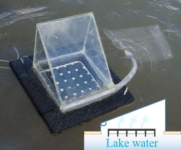*
From the top left corner, moving clockwise, the four images
depict: University at Buffalo students performing an experiment,
clean drinking water, water evaporating, and black carbon wrapped
around plastic in water with evaporated vapor on a|more
You've seen Bear Grylls turn foul water into drinking water with
little more than sunlight and plastic.
Now, academics have added a third element a carbon-dipped paper a
that may turn this survival tactic into a highly efficient and
inexpensive way to turn saltwater and contaminated water into
potable water for personal use.
The idea, which could help address global drinking water
shortages, especially in developing areas and regions affected by
natural disasters, is described in a study published online today
(Jan. 30, 2017) in the journal Global Challenges.
"Using extremely low-cost materials, we have been able to create a
system that makes near maximum use of the solar energy during
evaporation. At the same time, we are minimizing the amount of
heat loss during this process," says lead researcher Qiaoqiang
Gan, PhD, associate professor of electrical engineering in the
University at Buffalo School of Engineering and Applied Sciences.
Additional members of the research team are from UB's Department
of Chemistry, Fudan University in China, the University of
Wisconsin-Madison and the lab of Gan, who is a member of UB's New
York State Center of Excellence in Materials Informatics and UB's
RENEW Institute, an interdisciplinary institute dedicated to
solving complex environmental problems.
**Solar vapor generator**
To conduct the research, the team built a small-scale solar still.
The device, which they call a "solar vapor generator," cleans or
desalinates water by using the heat converted from sunlight.
Here's how it works: The sun evaporates the water. During this
process, salt, bacteria or other unwanted elements are left behind
as the liquid moves into a gaseous state. The water vapor then
cools and returns to a liquid state, where it is collected in a
separate container without the salt or contaminants.
"People lacking adequate drinking water have employed solar stills
for years, however, these devices are inefficient," says Haomin
Song, PhD candidate at UB and one of the study's leading
co-authors. "For example, many devices lose valuable heat energy
due to heating the bulk liquid during the evaporation process.
Meanwhile, systems that require optical concentrators, such as
mirrors and lenses, to concentrate the sunlight are costly."
The UB-led research team addressed these issues by creating a
solar still about the size of mini-refrigerator. It's made of
expanded polystyrene foam (a common plastic that acts as a thermal
insulator and, if needed, a flotation device) and porous paper
coated in carbon black. Like a napkin, the paper absorbs water,
while the carbon black absorbs sunlight and transforms the solar
energy into heat used during evaporation.
The solar still coverts water to vapor very efficiently. For
example, only 12 percent of the available energy was lost during
the evaporation process, a rate the research team believes is
unprecedented. The accomplishment is made possible, in part,
because the device converts only surface water, which evaporated
at 44 degrees Celsius.
**Efficient and inexpensive**
Based upon test results, researchers believe the still is capable
of producing 3 to 10 liters of water per day, which is an
improvement over most commercial solar stills of similar size that
produce 1 to 5 liters per day.
Materials for the new solar still cost roughly $1.60 per square
meteraa number that could decline if the materials were purchased
in bulk. (By contrast, systems that use optical concentrators can
retail for more than $200 per square meter.) If commercialized,
the device's retail price could ultimately reduce a huge projected
funding gap a $26 trillion worldwide between 2010 and 2030,
according to the World Economic Forum a needed for water
infrastructure upgrades.
"The solar still we are developing would be ideal for small
communities, allowing people to generate their own drinking water
much like they generate their own power via solar panels on their
house roof," says Zhejun Liu, a visiting scholar at UB, PhD
candidate at Fudan University and one the study's co-authors.
---
**DOI: 10.1002/gch2.201600003**
**Extremely Cost-Effective and Efficient
Solar Vapor Generation under Nonconcentrated Illumination
Using Thermally Isolated Black Paper, Global Challenges (2017)**
**Abstract**
Passive solar vapor generation represents a promising and
environmentally benign method of water purification/desalination.
However, conventional solar steam generation techniques usually
rely on costly and cumbersome optical concentration systems and
have relatively low efficiency due to bulk heating of the entire
liquid volume. Here, an efficient strategy using extremely
low-cost materials, i.e., carbon black (powder), hydrophilic
porous paper, and expanded polystyrene foam is reported. Due to
the excellent thermal insulation between the surface liquid and
the bulk volume of the water and the suppressed radiative and
convective losses from the absorber surface to the adjacent heated
vapor, a record thermal efficiency of a88% is obtained under 1 sun
without concentration, corresponding to the evaporation rate of
1.28 kg (m2 h)a1. When scaled up to a 100 cm2 array in a portable
solar water still system and placed in an outdoor environment, the
freshwater generation rate is 2.4 times of that of a leading
commercial product. By simultaneously addressing both the need for
high-efficiency operation as well as production cost limitations,
this system can provide an approach for individuals to purify
water for personal needs, which is particularly suitable for
undeveloped regions with limited/no access to electricity.
---
[**http://www.sciencemag.org/news/2017/02/sunlight-powered-purifier-could-clean-water-impoverished**](http://www.sciencemag.org/news/2017/02/sunlight-powered-purifier-could-clean-water-impoverished)**DOI: 10.1126/science.aal0699**
**Sunlight-powered purifier could clean water
for the impoverished**
**By Robert Service**
**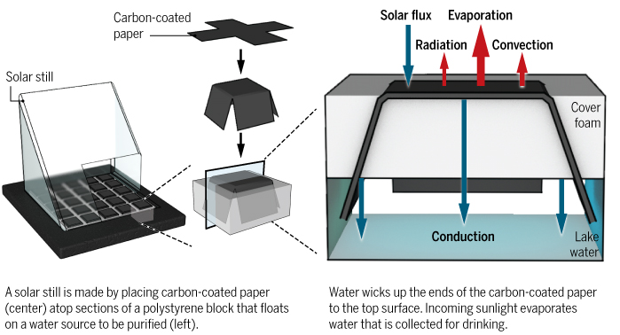**
One-tenth of the worldas population lacks clean water. Now,
researchers report they have developed a cheap solar still, which
uses sunlight to purify dirty water up to four times faster than a
current commercial version. The raw materials cost less than $2
per square meter. The technology will aallow people to generate
their own drinking water much like they generate their own power
via solar panels on their house roof,a says Zhejun Liu, a visiting
scholar at the State University of New York (SUNY) in Buffalo and
one of the studyas co-authors.
Solar stills have been around for millennia. Most are simple
black-bottomed vessels filled with water, and topped with clear
glass or plastic. Sunlight absorbed by the black material speeds
evaporation, which is trapped by the clear topping, and funneled
away for drinking water. Most pollutants donat evaporate, and so
are left behind. But much of the sunas energy is wasted in the
slow heating of a full vessel of water. Even the best stills need
to be about 6 square meters in size to produce enough water for a
single person for a day.
In recent years, researchers have improved stills using two
approaches. First, they design their stills so that only the very
top layer of water in the vessel is heated and evaporated, which
means less energy is lost. Second, theyave turned to nanomaterials
to absorb more of the sunas rays. But efficient light-absorbing
nanomaterials can cost hundreds of dollars per gram, making them
unrealistic for widespread use in developing countries where the
technology is needed most.
Qiaoqiang Gan, an electrical engineer at SUNY Buffalo, saw that
problem firsthand. His lab was already developing new
nanomaterials as absorbers for solar power cells, and wanted to
also use them in a solar still. But it quickly became apparent
that the materialas cost would never allow the technology to be
viable. So Gan began looking for cheap alternatives.
His teamas new device has three main components. Gan and his
colleagues start with a fiber-rich paperasort of like the paper
used to make currency. They coat this with carbon black, a cheap
powder left over after the incomplete combustion of oil or tar.
Next, they take a block of polystyrene foamathe stuff used to make
coffee cupsaand cut slices through it making 25 connected
sections. The foam floats on the untreated water and acts as an
insulating barrier to prevent sunlight from heating up too much of
the water below. The researchers then layer pieces of their paper
over each section, folding the ends down so that they dangle into
the water. The paper wicks water upward, wetting the entire top
surface of each of the 25 sections. Finally, a clear acrylic
housing sits on top.
During operation, evaporated water from the carbon paper is
trapped by the acrylic and funneled to a collection vessel, and
the paper wicks up additional water to replace it. Gan and his
colleagues report this week in Global Challenges that the setup
not only works, but that itas 88% efficient at channeling the
energy in sunlight into evaporating water. This allows a
1-square-meter-sized device to purify 1 liter of water per hour,
which is about four times faster than commercially available
versions, Gan says.
Equally important Gan adds, is that the still is cheap. He
estimates the materials needed to build it cost roughly $1.60 per
square meter, compared with $200 per square meter for commercially
available systems that rely on expensive lenses to concentrate the
sunas rays to speed evaporation. At that price, providing the
minimal water needed for a family of four might cost as little as
$5 for the raw materials per device. That cheap cost may not only
help people in impoverished regions, but also help aid workers
deploy cheap water purifiers to people affected by natural
disasters that wipe out safe drinking water sources. aWe think
this is an immediate application,a Gan says.
The new work is agood progress,a says Gang Chen, a mechanical
engineer at the Massachusetts Institute of Technology in
Cambridge, who has developed his own version of the technology in
recent years, which uses slightly different materials. The new
setup not only uses cheaper starting materials than anything on
the market, but makes freshwater much more quickly, he notes.
aThis is really important in solving many water challenges.a
The authors of the report have formed a company a Suny Clean Water
a to commercialize the work and are already in discussions with
other companies around the world to make the new technology
available.
---
[**http://onlinelibrary.wiley.com/doi/10.1002/gch2.201600003/full**](http://onlinelibrary.wiley.com/doi/10.1002/gch2.201600003/full)**DOI: 10.1002/gch2.201600003**
**Extremely Cost-Effective and Efficient
Solar Vapor Generation under Nonconcentrated Illumination
Using Thermally Isolated Black Paper**
**Zhejun Liu, e tal.**
**Abstract**Passive solar vapor generation represents a promising and
environmentally benign method of water purification/desalination.
However, conventional solar steam generation techniques usually
rely on costly and cumbersome optical concentration systems and
have relatively low efficiency due to bulk heating of the entire
liquid volume. Here, an efficient strategy using extremely
low-cost materials, i.e., carbon black (powder), hydrophilic
porous paper, and expanded polystyrene foam is reported. Due to
the excellent thermal insulation between the surface liquid and
the bulk volume of the water and the suppressed radiative and
convective losses from the absorber surface to the adjacent heated
vapor, a record thermal efficiency of a88% is obtained under 1 sun
without concentration, corresponding to the evaporation rate of
1.28 kg (m2 h)a1. When scaled up to a 100 cm2 array in a portable
solar water still system and placed in an outdoor environment, the
freshwater generation rate is 2.4 times of that of a leading
commercial product. By simultaneously addressing both the need for
high-efficiency operation as well as production cost limitations,
this system can provide an approach for individuals to purify
water for personal needs, which is particularly suitable for
undeveloped regions with limited/no access to electricity.
**1 Introduction**
Efficient solar energy-to-heat conversion for vapor/steam
generation is essential for various applications ranging from
large scale absorption chillers, desalination systems to compact
and portable applications including drinking water purification
and sterilization systems.[1-5] Conventional solar steam
generation techniques usually rely on costly and cumbersome
optical concentration systems to heat a bulk liquid.[6] Even
though some highly absorbing materials are utilized to enhance
solar absorption, such as charcoal,[7] sponge,[8] or cotton
cloth,[9] the energy conversion efficiency is still relatively low
(e.g., 30a40%[10]) due to the heat dissipation in the entire
liquid volume. Therefore, there is a significant need to develop
more efficient, self-powered, and highly portable solar energy
harvesting systems for vapor/steam generation. Low-cost and
broadband light absorbing micro/nanomaterials show promise in this
regard.
In recent years, plasmonic nanoparticles (NPs) and their
assemblies have been widely studied because of their unique light
and heat localization properties. In particular, it was revealed
that the localized heat effect can be used for new solar
vapor/steam generation that cannot be addressed using conventional
technologies that heat the entire fluid volume. For instance,
plasmonic metallic NPs[11-13] and nanorods[14, 15] dispersed in
aqueous solutions can generate vapor bubbles. However, due to
limited solar absorption bands, the resulted solar thermal
conversion efficiencies of these earlier works are relatively low.
For example, it was reported that Au NPs dispersed in water
obtained a solar thermal conversion efficiency of 24% (i.e., only
24% of the solar energy was transferred to generate vapor).[16] To
overcome this bandwidth limitation, broadband dark metallic
nanostructures (e.g., Au and Al-based NPs[17-20]) were developed
to enhance the overall solar-to-heat conversion efficiency (e.g.,
57.3% under illumination of 20 kW ma2 (i.e., 20 sun
concentration)[17] and 92.6% under illumination of 6 kW ma2 (i.e.,
6 sun concentration) using ultrabroadband black gold membrane
structures,[18] 77.8% under illumination of 4.5 kW ma2 (i.e., 4.5
sun concentration) using airlaid-paper-based Au NP structure[19]).
However, the intrinsically high cost of Au-based nanomaterial
(e.g., retail price of $395 mga1 for Au nanoshells[21]) is a
significant bottleneck for practical applications using these
systems. This is especially true when absorbing NPs are dispersed
throughout the bulk of a liquid (e.g., ref. [16]) and a
significant number is effectively wasted due to absorption and
scattering of the incident light by the NPs above.
To overcome this issue, floating substrates such as carbon
foam,[22] paper,[19] and nanoporous anodic alumina[17, 18, 20]
have been employed to localize the absorbing material at the
surface of water for more efficient and cost-effective solar steam
generation. In these platforms, the substrates functioned as
thermally insulating layers that reduce the heat transfer between
the vaporization region (i.e., the water surface) and the bulk
liquid. Due to the capillary action of these porous supports,
localized evaporation was realized with improved thermal
efficiencies (e.g., 64% under 1 kW ma2 illumination using
exfoliated graphite on carbon foam[22]). Additionally, it was
reported that the use of solar concentrators further improved the
thermal efficiencies of these systems, up to 85a90% (e.g., ref.
[17-20, 22]). However, in order to achieve these high
efficiencies, these platforms still require specialized
fabrication of highly absorbing, structured nanomaterials (e.g.,
black gold or aluminum NPs on nanoporous anodic alumina[17, 18,
20]) and/or porous hydrophilic supports (e.g., porous carbon foams
at the retail price of a$1.5 in.a3[23]), as well as costly solar
concentrating systems. These requirements impose prohibitively
high costs for practical applications over large areas.
In this work, we report an efficient carbon-based solar vapor
generation system based on carbon-coated paper (CP) affixed to
expanded polystyrene (EPS) foam. Due to the superior absorption,
heat conversion, and insulating properties of our CP-foam
structure, most of the absorbed energy can be used to evaporate
surface water with significantly reduced thermal dissipation
compared with previously reported architectures.[24-26]
Remarkably, we realized a record solar thermal conversion
efficiency of >88% under illumination of 1 kW ma2 with no solar
concentration. Furthermore, seawater desalination was also
demonstrated with reusable stable performance. By utilizing
extremely low-cost materials, and circumventing the need for solar
concentrators, economically viable large area systems will be
possible with no energy input required for operation. This
prospect is particularly attractive for addressing global
freshwater shortages, especially for individuals to purify water
for personal needs (i.e., a2 L da1) in developing regions.
**2 Results****2.1 CP for Solar Vapor Generation**In previously reported pioneering works based on porous
materials (e.g., ref. [17-20, 22]), capillary force is essential
to assist the enhanced vapor generation process since it is much
easier to vaporize small droplet diffused into the pores than to
heat and vaporize the bulk volume. In principle, hydrophilic
porous materials are generally suitable for this purpose.[27] In
this work, we selected a fiber-rich nonwoven paper (Texwipe
TX609[28]) as our support since it is extremely low-cost (i.e.,
retail price of a$1.05 ma2), chemical-binder-free, and has
excellent water transport properties. Its microstructure is shown
in Figure 1A, consisting of 10a20 I1/4m wide paper-fiber bundles. We
then dye it using low-cost carbon black powders (e.g., Sid
Richardson Carbon & Energy Co., retail price of $2.26 lba1;
see Section S1 in the Supporting Information for fabrication
details and stability/durability test results). As a result, the
paper fibers were coated with carbon nanoparticles, as shown in
Figure 1B. The direct comparison between the white paper and the
carbon-coated paper is shown in the inset of Figure 1C. The
optical absorption of the CP is very strong with the average
absorption of a98% throughout the visible to near IR domain (from
250 nm to 2.5 I1/4m, measured by a spectrophotometer equipped with an
integration sphere, Shimadzu UV-3150). This strong broadband
optical absorption is particularly promising for low-cost
solar-to-heat conversion. It should be noted that although the
latest reported Al-nanoparticle structure is also inexpensive if
implemented in yield productions,[20] the inflammability of 5a30
nm sized Al-NPs imposes a potential safety issue (see the Safety
Data Sheet of Al NPs,[29] code H261[30]). Therefore, the proposed
CP structures are also superior since they are environmentally
benign and safe to handle during production.
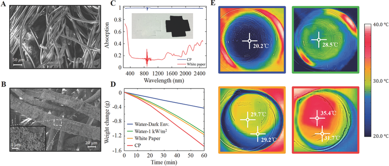

To demonstrate the baseline for solar vapor generation
performance, we first performed a direct comparison under several
different conditions as shown in Figure 1D (see Section S2 in the
Supporting Information for experiment details). In this
experiment, the open area of the beaker is 35.3 cm2, containing
a165 g water. In the dark environment (i.e., at room temperature
of 21 A degC and humidity of 10%), the water weight loss is 0.44 g
ha1. Therefore, the average evaporation rate in the dark
environment is 0.125 kg (m2 h)a1, which will be subtracted from
all subsequent measured evaporation rates to eliminate the effect
of natural water evaporation. Under the solar illumination using a
solar simulator (Newport 69920 with the solar intensity of 1 kW
ma2, i.e., AM1.5), the weight loss increased to 1.11 g ha1. After
that, we put a 4 A 4 cm2 white paper and a 4 A 4 cm2 CP on top of
the water surface, the weight change increased to 1.16 and 1.48 g
ha1, respectively. To interpret the weight change difference, we
employed a portable thermal imager (FLIR ONE) to characterize the
temperature of these samples. The thermal imaging characterization
was confirmed by a direct measurement using a thermocouple sensor
probe (see Section S3 in the Supporting Information), indicating a
reasonable accuracy (i.e., acurrency0.4 A degC in the 33a35 A degC range). As
shown in Figure 1E, the CP surface temperature increased to the
highest number of 35.4 A degC due to the enhanced solar-to-heat
conversion. However, this heating effect is not well isolated from
the bulk water (i.e., the bulk water was heated to 31.7 A degC),
resulting in the inefficient vapor generation effect. One can see
that the water evaporation speed with the CP is 1.33 times higher
than that of pure water under the 1 kW ma2 solar illumination,
which is only an incremental improvement. Next, we will discuss
the thermal-isolating strategy to confine the heating effect at
the top surface for more efficient vapor generation.
**2.2 Efficient Vapor Generation Using Thermally Isolated CP**
One of the most attractive features claimed by previously reported
nanomaterials for solar-vapor generation is the surface heating
effect with no need to heat the bulk volume of the water (e.g.,
ref. [17-20, 22]). According to pioneering studies employing
carbon foams,[22] nanoporous alumina,[17, 18, 20] and floating
paper,[19] porous supports transport small water droplets to the
upper surface directly through the structure of the support.
Although they are also designed to serve as thermal insulators,
the finite thickness, large contact area, and fluid transport of
the porous substrates lead to relatively poor thermal insulation
performance (e.g., the thermal conductivities are 0.49 W (m K)a1
in ref. [19] and 0.426 W (m K)a1 in ref. [22]], respectively).
Therefore, a better thermal isolation will improve the solar vapor
generation performance. In this work, we propose a better strategy
to make full use of the capillary force of the porous paper to
draw fluid up around the support rather than through it, and thus
minimize the thermal loss to the bulk fluid below. As shown by the
upper panel in Figure 2A, we inserted a 6 mm thick EPS foam slab
under the CP to thermally isolate the porous paper from the bulk
water. The thermal conductivity of this EPS foam is 0.034a0.04 W
(m K)a1,[31] one of the lowest thermal conductivities available
among extremely low-cost materials. In this configuration, the
only contact area between the water and CP is at the edges of the
porous paper (i.e., a line contact). This significantly reduces
the region of fluid transport compared to placing the paper[19] or
carbon foam[22] directly on the water surface (see the lower panel
in Figure 2A). In this case, the paper contacting the water along
the sides of the EPS foam transports the water droplets to the
upper surface to facilitate evaporation. It should be noted that
during testing, the upper surface of the CP was always wet,
indicating that this reduction in transport area does not limit
the evaporation rate of the system. A more detailed
characterization of the liquid transportation capability of the CP
is shown in Section S4 (Supporting Information).
To eliminate the water evaporation from other open areas, the
surrounding exposed water surface was covered with EPS foam with a
square hole for the CP (Figure 2B). To demonstrate the thermal
isolation effect, we then characterized the surface temperature
with and without the EPS foam under the CP, as shown in Figure 2C.
Under the solar light illumination with the intensity of 1 kW ma2,
the upper surface temperature of the CP increased from 32.9 A degC
(lower panel) to 44.2 A degC with the EPS foam insulation (upper
panel). The vapor generation performance is shown in Figure 2D.
One can see that the water mass change is improved to 1.28 kg (m2
h)a1, which is 3.0 times greater than that of the pure water case
and 2.0 times greater than that of CP without EPS foam isolation.
This evaporation rate is better than the best reported data under
1 sun illumination with no solar concentration using exfoliated
graphite (i.e., circles taken from Figure 2D of ref. [22]). In
principle, one would only need a a0.2 m2 structure to produce 2 L
of freshwater to meet an individual's daily needs assuming 8 h of
nonconcentrated solar illumination. Solar concentration will
enhance this generation rate further, as will be discussed next.
**2.3 High Solar Thermal Conversion Efficiency**
In most previously reported works,[17-20, 22] the sample surface
is always wet, indicating that the performance is limited by
surface temperature only. Therefore, the ultimate performance can
be improved by introducing concentrated solar illumination. Next,
we will analyze the vapor generation performance under moderate
solar concentration conditions to better compare with previously
reported nanostructures. In this experiment, an inexpensive planar
PVC Fresnel lens (e.g., OpticLens, $2.39 per piece with the area
of 26 cm A 17.8 cm) was employed to focus the incident light from
the solar simulator. As shown in Figure 3A, when the solar light
was concentrated by 3, 5, 7, and 10 times, the water mass change
was increased to 3.66, 6.24, 9.34, and 13.30 kg (m2 h)a1,
respectively. To characterize the enhanced surface heating effect
more accurately, we then employed two thermocouple sensor probes
to measure the temperature of vapor and bulk water (see Figure S3
in the Supporting Information). As shown by solid curves in Figure
3B, the vapor temperature increased sharply within the first 3 min
and reached a steady state after 10 min. In contrast, the
temperature of bulk water increases slowly and continuously as
shown by dashed lines in Figure 3B. To evaluate the solar-vapor
generation performance quantitatively, we then calculate the solar
conversion thermal efficiency, I*th, which is described by Equation
(1)[22]
display math(1)
where math formula is the mass flux, hLV the total enthalpy of
liquid-vapor phase change, Copt the optical concentration, and qi
the normal direct solar irradiation (i.e., 1 kW ma2).
Particularly, the calculation of the total enthalpy of
liquid-vapor phase change, hLV, should consider both the sensible
heat and the temperature-dependent enthalpy of vaporization (see
Section S4 for details of this equation and calculation in the
Supporting Information). Using Equation (1), we obtained the solar
conversion thermal efficiency, I*th, of 88.6% under 1 sun
illumination, and 94.8% under 10 times solar concentration, as
shown in Figure 3C. Compared with previously reported exfoliated
graphite,[22] Au NPs,[18] and black gold membranes,[17] this
CP-foam structure realized a very high solar thermal conversion
efficiency especially under low optical concentration condition
(see direct comparison in Figure 3D calculated by similar data
processing procedures; see Section S5 in the Supporting
Information for more details). It should be noted that since the
reported CP structure does not require any special
micro/nanofabrication process, the system is extremely low-cost
(cheaper than that of the concentrator) and amenable to scaling up
over large or huge areas for real applications. Therefore, there
is no need to employ large area solar concentrating systems for
real applications.
**Figure 3.**
**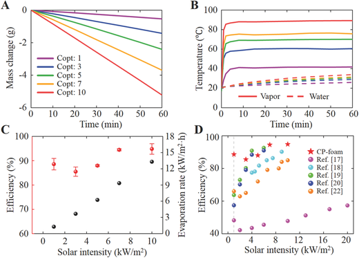**
A) The water mass change as a function of time under 1, 3, 5, 7,
and 10 times concentrated solar illumination, respectively. B) The
temperature change as a function of time under 1, 3, 5, 7, and 10
times concentrated solar illumination, respectively. The solid
lines represent vapor temperatures measured by a thermometer
installed above the CP-foam. The dashed lines represent bulk water
temperatures measured under the foam, while line colors are as for
the legend of (A). C) The solar thermal conversion efficiency (red
dots) and corresponding evaporation rate (black dots) as a
function of solar intensity. D) Direct comparison of solar thermal
conversion efficiencies obtained by previously reported structures
(data from refs. [17-20, 22]) and the CP-foam.
In addition, this I*th actually describes the energy consumption in
the vapor, and has two major components: the energy used for
water-to-vapor phase change, and the energy used to heat the
water/vapor. A larger I*th does not necessarily correspond to a
higher vapor generation rate. For a given value of I*th, a higher
temperature of the generated vapor will actually result in a lower
generation rate since more energy is used to heat the water.
Therefore, in terms of solar vapor generation rate, it is
necessary to analyze the theoretical upper limit and thermal loss
channels in order to estimate the opportunity available for
improvement.
**2.4 Theoretical Upper Limit**
The ideal condition for solar vapor generation is to convert
liquid water to vapor at ambient temperature with no energy used
to heat either the bulk or evaporated water. Radiative loss and
convective loss are both assumed to be zero. In this case, based
on our experimental conditions (i.e., at ambient temperature of 21
A degC), the ideal vapor generation rate is 1.466 kg (m2 h)a1 assuming
I*th = 1 and hLV in Equation (1) is 2455.6 kJ kga1 at ambient
temperature.[32] Based on this ideal vapor generation rate, we can
straightforwardly estimate I*th obtained in our experiment, i.e.,
1.28/1.466 = 87.3%, which only considers the energy used to
produce vapor at room temperature. Detailed thermal loss
mechanisms are automatically excluded in this simple estimation.
However, this theoretical upper limit is unlikely realized since
thermal losses are inevitable in these systems. Additionally,
under 10A solar concentration, this theoretical maximum is 14.66
kg (m2 h)a1. Therefore, even if these theoretical upper limits can
somehow be further approached using advanced (and likely
expensive) nanomaterials in the near future, the opportunity for
improvement is relatively limited. As a result, the more pressing
issue in developing technologies for high performance solar vapor
generation is cost, which is the primary advantage of our proposed
structure and system.
**2.5 Loss Channels**
Recently, a new strategy was reported to demonstrate the close to
100 A degC steam generation under 1 sun enabled by a floating
structure with athermal concentration.a[33] A detailed thermal
loss analysis was performed, revealing that radiative loss and
convective loss are two major thermal loss channels in the solar
vapor generation systems. The radiative and the convective losses
per area are expressed by Equations (2) and (3), respectively
where Iu is the emissivity of the CP (i.e., 0.98), I the
StefanaBoltzmann constant (i.e., 5.67 A 10a8 W (m2 K4)a1), T2 the
temperature at the surface of the CP, T1 the temperature of the
adjacent environment, and h the convection heat transfer
coefficient (assumed to be 10 W (m2 K)a1[33]). Using these two
equations, it was estimated that the radiative loss from the 100
A degC blackbody absorber surface to the ambient environment (20 A degC)
is a680 W ma2 and the convective loss is a800 W ma2. Following
this theoretical estimation, when the absorber surface is 44.2 A degC
(our experimental observation), the radiative loss to ambient is
a147 W ma2 and the convective loss is a232 W ma2, corresponding to
a total of 37.9% energy loss (i.e., 14.7 + 23.2%). In this case,
it seems that an efficiency a90% is impossible. But why can we
observe a record high vapor generation rate under 1 sun?
To interpret the unique features and physics of the proposed
CP-foam architecture, the thermal environment and heat transfer
diagram is analyzed in Figure 4A. First, the downward thermal
radiation is suppressed. According to the previously reported
experimental characterization, the reflection of a 3 mm thick EPS
foam slice is in the range of 40a60% over the spectral region of
thermal emission with a10% thermal radiation absorption.[34]
Therefore, under thermal equilibrium condition, the temperature of
the EPS-foam surface is very close to the bottom surface of the CP
layer so that the downward radiative loss from the CP layer is
significantly suppressed. In this case, the EPS foam employed in
our system actually serves as a thermal radiation shield (in
addition to its excellent thermal insulation characteristics),
which is superior over previously reported double-sided black
systems (e.g., ref. [22, 35]).
**Figure 4.**A) Energy balance and heat transfer diagram in the CP-foam
architecture during the vapor generation process. B) Zoom-in
diagram near the surface of the CP structure during the vapor
generation process.
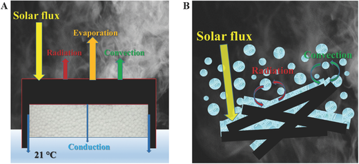
If we further analyze the microscopic thermal environment (Figure
4B), one can recognize that the CP surface is covered by a sheet
of water and surrounded by heated vapor. The absorbed solar energy
of the CP layer will first exchange thermal energy with water
sheet and vapor in this small region rather than directly emit
thermal radiation and exchange heat with the surroundings through
the convection. In particular, in many reported experiments to
identify the vapor temperature, a thermocouple was usually placed
on top of the absorber surface (e.g., ref. [18, 20, 22, 33]),
further demonstrating that the top surface of the absorber is
surrounded by heated vapor. Since the temperature of the adjacent
environment on top of CP absorber is very close to the temperature
of CP surface, the radiative and convective loss should be very
small. For instance, according to Equations (2) and (3), the
radiative loss from the 44.2 A degC surface under 1 sun to the a41.6
A degC vapor environment is a1.8% and the convective loss is only
a2.6%. Most absorbed solar energy is still used to evaporate the
water sheet on top of the absorber surface rather than being lost
through these two channels. This is the major physical mechanism
for the observed high vapor generation rate. This is also
applicable to other reported solar vapor generation systems (e.g.,
ref. [17, 19, 22, 27, 36-38]) since they are also covered by a
film of water and/or surrounded by heated vapor. However, this
physical mechanism was not detailed in previous reports.
More importantly, in a real enclosed solar steam system, the vapor
cannot be released immediately and the environment inside the
system is thermally isolated from the cooler surrounding
environment. Furthermore, typical acrylic or glass slabs are
opaque to mid-infrared radiation. Consequently, thermal radiation
cannot be emitted to the environment. Additionally, convective
energy transfers are also largely suppressed when the internal
environment is heated under near-thermal equilibrium conditions.
In this case, the radiative and convective losses in a real system
should be even more negligible, demonstrating the potential to
develop practical solar steam systems using extremely low-cost
materials. Intriguingly, in the latest report,[33] the highest
temperature of the generated steam was observed in a vapor
chamber, demonstrating the accuracy of our proposed physical
picture. In the next section, we will continue to demonstrate its
application for seawater desalination, a process to remove salts
and minerals to generate freshwater, representing a key solution
to address the emerging water scarcity faced by this world.[3-5]
2.6 Performance for Solar Desalination and the Effect of the Bulk
Water Temperature
Conventional desalination technologies are usually energy
demanding (e.g., reverse osmosis membrane technology consumes a2
kW h ma3[5]) with serious environment costs. It was estimated that
a minimum energy consumption for active seawater desalination is
a1 kW h ma3,[3] excluding prefiltering and intake/outfall pumping.
Passive solar desalination technology is particularly attractive
due to the electricity-free operation with minimum negative
impacts on the environment. To characterize the evaporation
performance and reusability of our CP-foam for desalination, here
we prepared salt water with 3.5 wt% NaCl and performed the solar
water evaporation experiment repeatedly. For each cycle, two
CP-foam samples were put on the surfaces of salt water and pure
water, respectively, and illuminated under 1 kW ma2 for 1 h. After
that, the CP samples were dried completely and reused for the next
cycle. As shown in Figure 5A, the evaporation rates of ten cycles
in pure water and salt water are both stable (i.e., 1.2a1.3 kg (m2
h)a1), demonstrating the reliability of the proposed CP-foam.
Considering the excellent wet and dry strength and autoclavable
features of the fiber-rich nonwoven paper (Texwipe TX609[28]), it
is particularly attractive for long term solar desalination
application, which is still under test.
**Figure 5.**A) The evaporation rate of CP-foam samples on salt water (blue
spheres) and pure water (red spheres) as the function of cycle
number. The two solid lines are guide for the eye to show the
stable performance. B) The SEM image of a CP sample after 1 h
evaporation in salt water. C) The evaporation rate of CP sample in
salt water over an 8 h evaporation period as a function of
illumination time. D) Photographs and E) thermal images of a
CP-foam on salt water at times corresponding to the blue spheres
in Figure 5C.
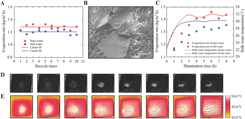
Noticeably, after the 1 h recycling test, a millimeter sized salt
crystal can be observed on the sample surface (see the first panel
in Figure 5D). Obviously, these white salt particles will
introduce scattering (see Figure 5B for scanning electron
microscope (SEM) image of salt crystal plates on the CP surface),
which should reduce the optical absorption of the CP sample. An
immediate question is whether this salt crystallization will
significantly degrade the performance of the vapor generation in
practice, which was not mentioned in previous reports (e.g., ref.
[19, 20] performed their experiments for 1a4 h only). To clarify
this issue, we then performed an 8 h continuous experiment in pure
water and salt water in a beaker, respectively. Intriguingly, one
can see that the evaporation speeds increased continuously and
saturated at the fourth to fifth hour at a1.32 and a1.42 kg (m2
h)a1 for salt water and pure water, respectively, as shown in
Figure 5C. Since the CP surface is always wet during the 8 h test
(indicating sufficient water transportation contributed by
capillary forces), the salt crystal did not grow further to cover
the entire surface. Instead, the salt crystal area even shrank
surprisingly, as shown by the photographs of the CP surface at
different time spots (see Figure 5D). When we repeated this
experiment (usually on the next day), this evaporation rate
increase can still be observed under identical experimental
conditions starting from the lower rate, indicating the stable and
reusable performance for longer term seawater desalination. As
shown by thermal images in Figure 5E, the average surface
temperature of the CP sample increased from 44 to 45 A degC gradually
and saturated at 53a54 A degC at the fourth to fifth hour. Therefore,
the immediate next question is what introduced this surface
temperature change?
According to the experimental data shown in Figures 1-3, the only
observed gradual change is the bulk water temperature, as shown by
dashed curves in Figure 3B. To identify this correlation, we
monitored the bulk temperature over 8 h, as shown by dotted curves
in Figure 5C. One can see that the bulk water temperature (from 22
to 32a33 A degC) and the evaporation rate changed coincidentally. This
observation demonstrated that the surface temperature of the
CP-foam is still related to the bulk liquid temperature. Due to
the excellent thermal insulation of the EPS foam support employed
in our structure, the temperature of the bulk water in this
experiment reached the thermal equilibrium after a5 h. Also, due
to the higher solubility of salt in warmer water, we observed that
the salt crystal shrank as the bulk and surface temperature
increases (i.e., Figure 5D). This vapor generation performance
should be improved if better thermal insulation materials are used
in the water container for small volume test. On the other hand,
if the bulk water temperature change is negligible in larger scale
vapor generation applications, one should not expect this obvious
evaporation rate change, as will be further validated in the
prototype system demonstration below.
**2.7 A Prototype Solar Still System**
A typical desalination solar still system is illustrated in Figure
6A: A box made by thermal insulating materials is filled by
seawater or salty water. A tilted transparent glass covers the box
to collect solar light. For conventional solar vapor generation
technology, light absorbing materials were usually placed at the
bottom of the basin to heat the entire liquid volume with fairly
low thermal efficiency (i.e., 30a40%[7]). To overcome this
weakness, we developed a 5 A 5 CP array as shown in Figure 6B
(i.e., 2 A 2 cm2 for each CP unit with the total area of 100 cm2),
which was placed in a polypropylene box (15 cm in diameter with
1500 g water). However, thermal isolating walls have not been
incorporated in this experiment. According to the thermal
distribution measurement, the temperature of CP surface increased
from 18.2 A degC (Figure 6C under dark condition) to 44.6 A degC (Figure
6D under 1 sun illumination). The slight nonuniformity of the
temperature distribution in Figure 6D was introduced by the
intensity distribution of the finite size of the light beam. To
evaluate its performance, we repeated the solar desalination
experiment using this large area sample (Figure 6E). Meanwhile,
two control samples were characterized: (1) a layer of black
aluminum foil placed at the bottom of the box (Figure 6F, its
optical absorption spectrum is shown in Figure S4 in the
Supporting Information) and (2) salty water with no CP-foam
(Figure 6G). As shown in Figure 6H, the mass change rate for the
CP-foam array is a1.275 kg (m2 h)a1 (with the estimated thermal
efficiency I*th of 88.2%), which is obviously better than those for
control samples (i.e., a0.408 kg (m2 h)a1 with I*th of 28.2% for
the bulk heating strategy, and a0.242 kg (m2 h)a1 with I*th of
16.7% for the bare salt water evaporation). It should be noted
that the evaporation rate in this large scale CP array experiment
did not increase obviously. Its bulk water temperature change is
also relatively small (20a25 A degC, as shown by the red dashed curve
in Figure 6H) due to the much larger amount of bulk water. In
contrast, the evaporation rates of those two control samples
increased slightly, corresponding to their bulk temperature
changes, as shown by green and blue dashed curves in Figure 6H.
The net water mass change produced by this 100 cm2 CP-foam
structure is 14.5 g after 5 h operation, which is a25 times of
that produced by a single unit (i.e., 0.58 g ha1, see Figure 3).
In this case, it is unnecessary to introduce a solar concentrator
to enhance the water evaporation rate, which is different from the
case for commercial concentrated photovoltaic systems. Due to the
extremely low manufacturing cost of the CP-foam, huge area
products can easily be realized using commercial paper printing
technologies at the price much lower than those for solar
concentrators. Therefore, portable or large scale systems directly
floating on seawater surfaces are possible to meet some low-end
freshwater generation needs, as will be demonstrated next. In this
case, the costs for seawater intake and pretreatment for
conventional reverse osmosis processes are largely avoided, which
provides a potential solution to low-cost freshwater generation
applications.
**Figure 6.**
A) Schematic illustration of a conventional desalination solar
still. B) Photograph of a 5 A 5 CP array with a total area of 100
cm2. C,D) Thermal images of CP array before (C) and after (D)
solar illumination. EaG) Photographs of experimental systems with
(E) the CP-foam array on salt water, (F) bare salt water with a
layer of black aluminum foil placed at the bottom, and (G) bare
salt water with no CP-foam. H) Hourly water weight change with the
CP-foam array on the water surface (red dots), black aluminum foil
at the bottom (green triangles), and salt water (blue squares) as
a function of illumination time. I) The photograph of a prototype
system paced on Lake Lasalle at the University at Buffalo. J) The
photograph of a control experiment with a commercial product
(left) and our system (right) during the experiment. Obvious mist
can be seen at the inner surfaces of the covers. K) The solar
intensity (upper panel) and outdoor temperature curves (lower
panel) from 8:00 a.m. to 6:00 p.m. on May 6, 2016 at the
University at Buffalo.
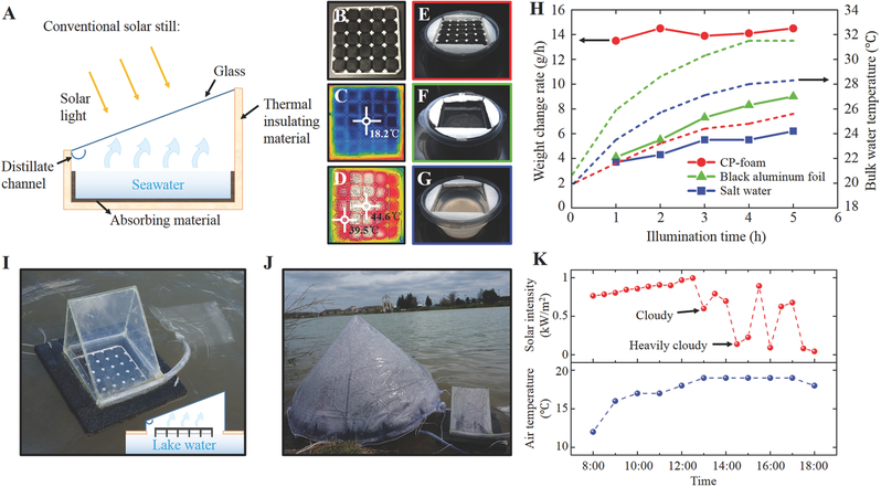
As shown in Figure 6I, a complete portable solar still system was
demonstrated by covering an open bottom box with a transparent
acrylic slab (with the 0.01 m2 5 A 5 CP-foam array directly in
contact with the open water below, see the inset of Figure 6I).
The clean water is collected by the distillate channel and guided
into a collection bag. We then placed this system on Lake Lasalle
at the University at Buffalo together with a commercial solar
still product with an effective area of 0.342 m2 (Aquamate Solar
Still at the retail price of $225), as shown in Figure 6J. It
should be noted that our CP-array can take the lake water
directly, while the commercial system needs to be actively fed.
After a 10 h operation in the outdoor environment on a
sunnyacloudy day at Buffalo with varying sunlight illumination
conditions (see Figure 6K for temperature and sunlight intensity
distribution), we obtained the generation productivities of 0.832
and 0.344 kg (m2 d)a1 for these two systems, respectively. The
performance of the CP-foam system is a2.4 times of the commercial
product. In addition, due to the scattering of the mist formed on
the cover (Figure 6J), the input light decreased significantly,
which is the next technical issue to optimize the performance of a
real system. A nontoxic superhydrophobic surface treatment for
antimist on the transparent glass cover[39] will improve the
system performance, which is still under investigation but beyond
the scope of this work. Consider the low-cost of the core elements
for solar-to-heat conversion, the solar still system can be
developed at a very low-cost (see Section S7 in the Supporting
Information), which is particularly promising for the distribution
in developing regions and in areas affected by natural disasters
where drinking water supply is temporarily interrupted.
**3 Conclusion**
In summary, we have developed an extremely cost-effective and
efficient carbon-based solar vapor generation system based on CP
supported by floating EPS foam. Due to the efficient solar
absorption of the CP, the superior thermal insulation of the EPS
foam support and suppressed radiative and convective loss in the
heated vapor environment, most of the absorbed solar energy is
confined within a thin surface layer of liquid, resulting in
efficient heat conversion and vapor generation. As a result, our
system achieved a record thermal conversion efficiency of a88%
under nonconcentrated solar illumination of 1 kW ma2. This
corresponds to an optimized vapor generation rate that is a3 times
greater than that of natural evaporation. In addition, stable and
repeated seawater desalination tests were performed in a portable
prototype both in the laboratory and an outdoor environment, and
achieved a water generation rate that was 2.4 times that of a
commercial product. Furthermore, by analyzing the theoretical
upper limit for solar vapor generation rates, we show that the
opportunity for improvement in vapor generation rates is
relatively limited. This indicates that the area that offers the
most potential for improvement is in the reduction of cost.
Compared with previously reported advanced nanostructures, this
CPaEPS system is extremely low-cost in terms of both materials and
fabrication, environmentally benign, and safe to handle during
production. These attributes enable this system to be easily
expanded to large scales, something that is of particular interest
in regions where access to freshwater is limited. It should be
noted that activated carbon structures and materials are widely
used in water and gas treatment applications (e.g., ref. [40]).
These functionalities are inherently compatible with our CP
structure, which may enable simultaneous freshwater generation and
treatment from heavily contaminated source water. Considering the
challenges in contaminated/waste water treatment and reuse, the
development of low-cost, electricity-free, and multifunctional
technologies represents new research avenues in carbon-based solar
vapor generation.
The shortage of freshwater and sanitation is one of the most
pervasive challenges afflicting people throughout the world. It
was predicted that by 2025, over half the nations in the world
will face freshwater stress, and by 2050, a75% of the world's
population could face water scarcity. Therefore, it is essential
to develop technologies for disinfection and decontamination of
water, and to increase water supplies through economic and
sustainable ways (i.e., at lower cost, smaller energy consumption,
and smaller environmental impacts). Membrane-based separations for
water purification and desalination are dominant technologies,
which, unfortunately, are usually energetically demanding with
serious environmental costs. There is emerging global interest in
developing new technologies to address these issues. Successful
demonstration of the portable solar steam generation system
represents a revolutionary product to beat the conventional
products both in performance and retail price, which is
particularly attractive for addressing global freshwater
shortages, especially in developing regions.
---
[**https://phys.org/news/2017-01-academics-ultimate-solar-powered-purifier.html**](https://phys.org/news/2017-01-academics-ultimate-solar-powered-purifier.html)
**Academics build ultimate solar-powered
water purifier**
---
**Related :**[**http://www.sciencemag.org/news/2016/08/solar-still-made-bubble-wrap-could-purify-water-poor**](http://www.sciencemag.org/news/2016/08/solar-still-made-bubble-wrap-could-purify-water-poor)
**Solar still made of bubble wrap could
purify water for the poor**
**By** **Robert F. Service**
Solar stills can make tainted water or seawater fit to drink. But
to produce more than a trickle, devices typically require
expensive lenses or other equipment. Not anymore. Today,
researchers report that theyave created a cheap solar still from
bubble wrap and other simple materials.
Solar stills have been used for thousands of years. The most basic
versions are water-filled vessels with black bottoms that absorb
the sunas rays, increasing evaporation of the water inside. Glass
or other clear material on top captures the vapor, and the
condensate drips into a collection vessel. To speed up this
process, modern versions use lenses or mirrors to collect about
100 times more sunlight. But the high cost of these solar
concentrators, typically on the order of $200 per square meter,
makes them unaffordable for many people.
Two years ago, researchers led by Gang Chen, a mechanical engineer
at the Massachusetts Institute of Technology in Cambridge,
unveiled an efficient solar absorber made from a layer of graphite
on floating carbon foam. The two layers were perforated, allowing
the water below to wick up to the graphite, where it was warmed by
the sun. The device worked, but much of the energy in the sunlight
radiated away. To boil water, the still needed additional devices
to concentrate 10 times the ambient sunlight to overcome the
infrared losses.
Chen and his colleagues wanted to do away with the extras. They
kept their idea of a spongy insulator floating on water. For their
current experiment, the researchers replaced the graphite solar
absorber with a thin layer of a bluish metal and ceramic composite
material used in commercial solar water heaters. This material
selectively absorbs visible and ultraviolet rays from the sun, but
it doesnat radiate heat in the infrared. Between this layer and
the foam, they placed a thin sheet of copper, an excellent heat
conductor. The researchers then punched holes through the
sandwichlike layers as before.
A problem remained. Much of the energy absorbed by the composite
was being swept away by convection, heat lost to the air moving
above the stillas top surface. The fix came from Chenas
16-year-old daughter, who was designing a cheap greenhouse for a
science fair experiment. She found that a top layer of bubble wrap
acted as an excellent insulator. So Chen and his student George Ni
covered their solar still in bubble wrap. And in todayas issue of
Nature Energy they report that their setup allowed them to boil
and distill water with no extra solar concentrator. Down the road,
Chen estimates that this will allow them to make large-area solar
stills for about one-twentieth the cost of conventional
technology.
aThis work certainly represents a key step forward,a write
materials scientists Wen Shang and Tao Deng from Shanghai Jiao
Tong University in China in a commentary accompanying the report.
Chen believes the low-cost apparatus could help purify wastewater
near fracking sites, for example. Typically, companies work to
evaporate water from wastewater ponds to concentrate and remove
the contaminants. A cheap solar sponge could speed the cleanup.
To be useful for desalination or other drinking water
applications, the device needs another plastic or glass layer on
top to collect the water vapor. This could increase the systemas
efficiency by trapping more heat and boosting evaporation, Chen
says.
Creating a purification system would be no small task. Chen
estimates it would require 20 to 40 square meters of the solar
still material to provide 50 liters of water per day, the minimum
that United Nations says a person needs for daily life.
---
**Related :**[**http://onlinelibrary.wiley.com/doi/10.1002/adma.201500135/full**](http://onlinelibrary.wiley.com/doi/10.1002/adma.201500135/full)
**A Bioinspired, Reusable, Paper-Based System
for High-Performance Large-Scale Evaporation**
**Yanming Liu, et al.**
**Abstract**
A bioinspired, reusable, paper-based gold-nanoparticle film is
fabricated by depositing an as-prepared gold-nanoparticle thin
film on airlaid paper. This paper-based system with enhanced
surface roughness and low thermal conductivity exhibits increased
efficiency of evaporation, scale-up potential, and proven
reusability. It is also demonstrated to be potentially useful in
seawater desalination.
---