Genepax Water Energy System -- articles & patents
 **[rexresearch.com](../index.htm)**
---
**Mitsuru
SUEMATSU**
**Genepax Water Energy System**
---
**Genepax : **
**Contact:**
**Jun Onishi [PR Manager]**
**Email: press@genepax.co.jp**
---
****
**New Fuel Cell System 'Generates
Electricity with Only Water, Air'**
**by** **Kouji Kariatsumari**
**(Nikkei Electronics)**
Genepax Co Ltd explained the technologies used in its new fuel
cell system "Water Energy System (WES)," which uses water as a
fuel and does not emit CO2.
The system can generate power just by supplying water and air
to the fuel and air electrodes, respectively, the company said
at the press conference, which took place June 12, 2008, at the
Osaka Assembly Hall.
The basic power generation mechanism of the new system is
similar to that of a normal fuel cell, which uses hydrogen as a
fuel. According to Genepax, the main feature of the new system
is that it uses the company's membrane electrode assembly (MEA),
which contains a material capable of breaking down water into
hydrogen and oxygen through a chemical reaction.
Though the company did not reveal the details, it "succeeded in
adopting a well-known process to produce hydrogen from water to
the MEA," said Hirasawa Kiyoshi, the company's president. This
process is allegedly similar to the mechanism that produces
hydrogen by a reaction of metal hydride and water. But compared
with the existing method, the new process is expected to produce
hydrogen from water for longer time, the company said.
With the new process, the cell needs only water and air,
eliminating the need for a hydrogen reformer and high-pressure
hydrogen tank. Moreover, the MEA requires no special catalysts,
and the required amount of rare metals such as platinum is
almost the same as that of existing systems, Genepax said.
Unlike the direct methanol fuel cell (DMFC), which uses
methanol as a fuel, the new system does not emit CO2. In
addition, it is expected to have a longer life because catalyst
degradation (poisoning) caused by CO does not occur on the fuel
electrode side. As it has only been slightly more than a year
since the company completed the prototype, it plans to collect
more data on the product life.
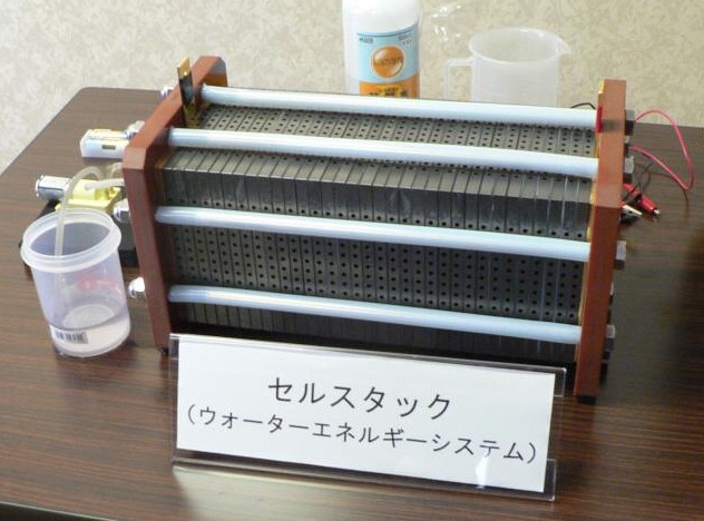
At the conference, Genepax unveiled a fuel cell stack with a
rated output of 120W and a fuel cell system with a rated output
of 300W. In the demonstration, the 120W fuel cell stack was
first supplied with water by using a dry-cell battery operated
pump. After power was generated, it was operated as a passive
system with the pump turned off.
This time, the voltage of the fuel cell stack was 25-30V.
Because the stack is composed of 40 cells connected in series,
it is expected that the output per cell is 3W or higher, the
voltage is about 0.5-0.7V, and the current is about 6-7A. The
power density is likely to be not less than 30mW/cm2 because the
reaction area of the cell is 10 x 10 cm.
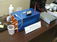
Meanwhile, the 300W fuel cell system is an active system, which
supplies water and air with a pump. In the demonstration,
Genepax powered the TV and the lighting equipment with a
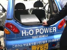
lead-acid battery charged by using the system. In addition, the
300W system was mounted in the luggage room of a compact
electric vehicle "Reva" manufactured by Takeoka Mini Car
Products Co Ltd, and the vehicle was actually driven by the
system.
Genepax initially planned to develop a 500W system, but failed
to procure the materials for MEA in time and ended up in making
a 300W system.
For the future, the company intends to provide 1kw-class
generation systems for use in electric vehicles and houses.
Instead of driving electric vehicles with this system alone, the
company expects to use it as a generator to charge the secondary
battery used in electric vehicles.
Although the production cost is currently about YEN2,000,000
(US$18,522), it can be reduced to YEN500,000 or lower if Genepax
succeeds in mass production. The company believes that its fuel
cell system can compete with residential solar cell systems if
the cost can be reduced to this level.
---
[**http://techon.nikkeibp.co.jp/english/NEWS\_EN/20080616/153301/**](http://techon.nikkeibp.co.jp/english/NEWS_EN/20080616/153301/)
( Jun 16, 2008 )
**Genepax President Interviewed on 'Water
Energy System'**
by
**Kouji Kariatsumari**
**( Nikkei Electronics )**
**Genepax's New Fuel Cell System**
Kiyoshi Hirasawa, president of Genepax Co Ltd, unveiled part of
the reaction mechanism of the company's new fuel cell system
called "Water Energy System" in an interview with Nikkei
Electronics.
The system, which is capable of generating power with water and
air, was first presented June 12, 2008. As reported in our
previous article, the system produces hydrogen through a
chemical reaction between water and a metal (or a metal
compound) on the fuel electrode side (See related article).
Genepax uses a metal or a metal compound that can cause an
oxidation reaction with water at room temperature, the company
said. Metals that react with water include lithium, sodium,
magnesium, potassium and calcium. The main feature of the Water
Energy System is that it can be operated for a longer period of
time by controlling the reaction of the metal or the metal
compound, the company said.
According to Genepax, the metal or the metal compound is
supported by a porous body such as zeolite inside the fuel
electrode of the membrane electrode assembly (MEA). The products
of the hydrogen generation reaction dissolves in water, and the
water containing them will be discharged with water inside the
system. Upon the completion of the reaction, the generation of
hydrogen and power stops.
Considering the commercialization of the system, Genepax is
conducting evaluation tests and plans to release test data.
---
[**http://en.wikipedia.org/wiki/Genepax**](http://en.wikipedia.org/wiki/Genepax)
**News Release**
...Genepax demonstrated the car in the Japanese city of Osaka
on 12 June 2008. Genepax Claims that one liter (2.1 pints) of
any kind of waterrain, river or sea (even tea, stated the press
release)is all that is needed to run the engine for about an
hour at a speed of 80 km/h (50 mph). However, their claims that
a 300 watt (0.4 horsepower) engine could drive the car (the
weight of which has not been specified) at this speed and for
this duration despite wind resistance / Automobile drag
coefficients and other energy-draining forces warrants further
investigation.
The demonstration vehicle was a Takeoka Reva, a small electric
car whose manufacturer claims a range of 85 km running on its
standard set of batteries, which take 8 hours to charge off the
mains at 100 V on a 15 A circuit. A charge of up to 12 kWh for a
range of 85 km suggests that the micro car draws about 40 times
more power than the claimed rating of the fuel cell. This would
indicate that during the test drive the fuell cell could have
contributed little more than 2% of the power used, the remainder
being drawn from the previously charged batteries...
---
[**http://www.youtube.com/watch?v=Jivb7lupDNU#at=27**](http://www.youtube.com/watch?v=Jivb7lupDNU#at=27)[**http://www.reuters.com/video/2008/06/13/water-fuel-car-unveiled-in-japan?videoId=84561**](http://www.reuters.com/video/2008/06/13/water-fuel-car-unveiled-in-japan?videoId=84561)
**Japanese company Genepax presents its
eco-friendly car that runs on nothing but water.**
The car has an energy generator that extracts hydrogen from
water that is poured into the car's tank. The generator then
releases electrons that produce electric power to run the car.
Genepax, the company that invented the technology, aims to
collaborate with Japanese manufacturers to mass produce it.
**[ [FLV](reutersvideo.flv)
]
3.5 MB**
---
**WATER ENERGY SYSTEM**
**JP2006244714**
**Mitsuru SUEMATSU**
**2006-09-14**
**[ [PDF](JP2006244714.pdf) ]**
**Abstract --**- PROBLEM TO BE SOLVED: To provide a water
energy system generating electric power using pure water as fuel
under normal temperature. SOLUTION: The water energy system 1
has a cell in which a fuel electrode 3 and an oxygen electrode 4
are faced with each other through a catalyst 2 same as a general
fuel cell. The fuel electrode 3 is formed by carrying platinum
on a sintered body of fine powder of zeolite, coral sand, and
carbon black, the oxygen electrode 4 is formed by carrying
ruthenium on the sintered body of fine powder of zeolite and
carbon black. Electric power is generated under normal
temperature by supplying pure water 5 to the fuel electrode 3
and air to the oxygen electrode 4.
The present invention relates to water energy
system capable of water as a fuel, power generation is
performed at room temperature atmosphere.
Various fuel cells have been proposed in the prior art.
Fuel cells are devices that generate electricity by utilizing
an electrochemical reaction, depending on the type of material
constituting the cell, the material various kinds are used as
fuel.
For example, organic materials such as aldehydes and methanol
is used.
Here, in a general fuel cell, to be able to supply hydrogen
efficiently for the fuel electrode, is reformed through a fuel
reformer before being supplied to the fuel electrode directly
to the fuel.
As the system for oxidation is supplied to the fuel electrode
of the cell to the fuel directly, for example, direct methanol
fuel cells are known.
The object of the present invention is that without using a
fuel such as methanol, we propose a water energy system
capable of performing power generation under normal
temperature by using pure water.
In order to solve the above problems, it is opposed disposed
sandwiching an electrolyte and oxygen electrode and the fuel
electrode, and pure water is supplied to the fuel electrode,
supplying oxygen to the oxygen electrode, water energy system
of the present invention, the subject to the electrochemical
reactions occurring at the oxygen electrode and the fuel
electrode causes the output DC power from these poles, as the
fuel electrode, the platinum is supported on a sintered body
of fine powders of carbon black zeolites, and coral sand and
is characterized in that using, as the oxygen electrode, is
used in which ruthenium is supported on a sintered body of
fine powders of carbon black and zeolites.
According to the experiments of the present inventors, in the
water energy system according to the present invention, when
supplying pure water directly to the fuel electrode, hydrogen
contained therein is oxidized and decomposed efficiently, and
a power generating operation efficiently at room temperature
under be done has been confirmed.
Therefore, according to the present invention, as
conventional, without the use of fuel gases such as methanol,
it is possible to realize a fuel cell system capable of
performing efficient power generation through a simple
mechanism.
The following describes an embodiment of a water energy system
with reference to the drawings, the present invention has been
applied.
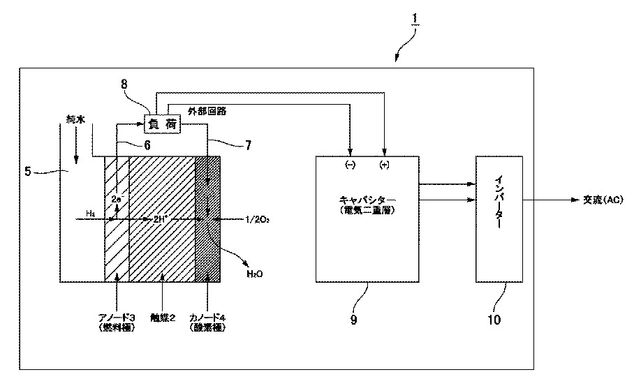
Figure 1 is a schematic diagram of the water energy system
according to the present embodiment.
The water energy system 1 is a system that generates power by
an electrochemical reaction of the catalyst with water, a
basic configuration is the same as that of a general fuel
cell.
As shown in the figure, the water energy system 1, is
sandwiched between the catalyst 2, the cell of the
configuration are oppositely disposed (cathode) fuel electrode
3 oxygen electrode 4 (anode) is a structure which is connected
to a large number of series are.
Is shown only one cell in FIG.
The fuel electrode 3, by the catalytic, hydrogen pure water 5
is supplied directly contained therein is electrolysis
negative hydrogen ions and electrons.
The catalyst, oxygen air is supplied from the outside to the
oxygen electrode and the other four are included therein are
generated water by reduction reaction with hydrogen ions.
Through a recovery passage (not shown), water is produced is
caused to circulate on the side of the fuel electrode 3.
Oxygen electrode 4 and the fuel electrode 3 is connected to
the external load 8 via conductor 6, 7 being drawn from them.
Motor is driven by direct current, an external load 8, and the
like lamp.
It is also possible to, or instead of the external load 8,
with this, stored in a secondary battery 9, such as electric
double layer capacitor, the conductors 6 and 7, is used as
capable of supplying AC power source AC via an inverter 10 .
In the present embodiment, as the fuel electrode 3, is used as
the platinum is supported on a sintered body of fine powders
of carbon black zeolites, and coral sand.
As the oxygen electrode 4, I have used as the ruthenium is
supported on a sintered body of fine powders of carbon black
and zeolites.
I will explain the power generating operation of water energy
system 1 of this configuration.
When supplied to the fuel electrode 3 of pure water 5,
hydrogen and oxygen is produced which is electrolyzed,
hydrogen splits into negative hydrogen ions and electrons by
the electrochemical reaction.
This reaction is an oxidation reaction because hydrogen emit
electrons.
Hydrogen ions produced move to the oxygen electrode 4 through
the catalyst 2.
There are ion-permeable but electron is not passed, the
negative electrons are extracted to the outside via conductor
6 catalyst 2.
Meanwhile, the air has been fed to the oxygen electrode 4, the
hydrogen ions that are supplied through the catalyst 2, and
the electrons supplied via an external circuit to the
reduction reaction, the oxygen contained therein is water are
produced.
Generating electricity by it.
Is a schematic diagram of the water energy system according to
the present invention.
1 Water energy system
2 catalyst
3 fuel electrode
4 oxygen electrode
5 pure water
6 and 7 leads
8 load
9 secondary battery
10 inverter
---
**WATER ENERGY SYSTEM** **JP2005281847** **KR20060098203** **KR20060062306**
**[ [PDF](JP2005281847A.pdf) ]**
Inventor: SUEMATSU MITSURU
Applicant: SUEMATSU MITSURU; MAEDA JUNICHIRO
2005-10-13
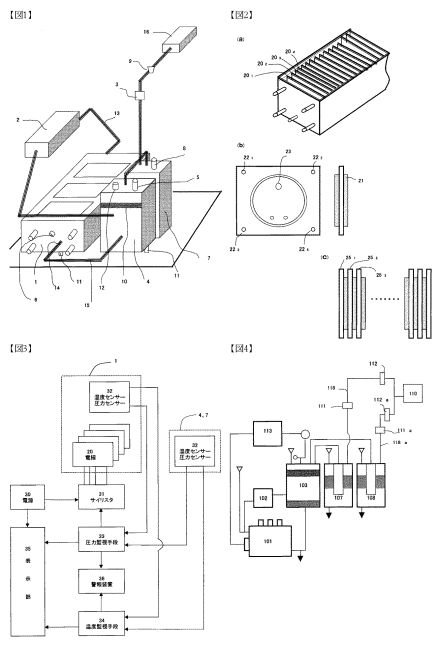
PROBLEM TO BE SOLVED: To provide a compact and simple system
capable of electrolyticall decomposing a 10% caustic soda
solution to produce oxyhydrogen gas under low pressure, thereby
using the oxyhydrogen gas instead of ordinary fuel such as
propane gas. ; SOLUTION: The water energy system is composed of:
an electrolyzer 1 injected with a caustic soda solution of a
prescribed concentration as electrolytic water; a plurality of
electrodes arranged on the electrolyzer at prescribed intervals
and each having a gas port for gas passage on the upper part;
spacers arranged between the plurality of electrodes and forming
a prescribed region between each electrode; an electricity
control circuit of applying prescribed voltage current; a cooler
2 of cooling produced gas introduced from the gas exhaust port
13 of the plurality of electrodes; a defoaming apparatus 4 where
a ceramic catalyst for removing foam coexisting in the cooled
produced gas is arranged at the inside; and a water solution
mixer 7 of mixing the gas from the defoaming apparatus into
water and a prescribed filler. The gas from the mixer is fed to
a gas stove 16 or the like, and is burnt.
---
**HYDROGEN GENERATING DEVICE, FUEL CELL AND
POWER GENERATION SYSTEM**
**WO2007094084**
**JP2010073325**
PROBLEM TO BE SOLVED: To provide a power generation module used
for a power generation system in which power generation is
carried out under normal temperature by using pure water as
fuel. ; SOLUTION: The power generation module 4 of a power
generation system is formed by laminating gaskets 43, partition
plates 44, and current collector plates 45 at both sides of an
electrode assembly 42 as a center, between a pair of clamp
plates 41. Pure water is supplied to an anode-side electrode
plate 47 from a pure water supply groove provided on the surface
of the partition plate through pure water supply holes 41c to
45c from outside of the clamp plate 41, and air taken in from an
air intake formed at outer peripheral end surface of the
separation plate is supplied to a cathode-side electrode 48 from
an air supply groove provided on another surface thereof. A
desired power generation capacity can be obtained by adding and
connecting in series electrode joint bodies 42 and partition
plates 44.
---
**Drive Unit, Hydraulic Working Machine,
and Electric Vehicle**
**US7971671**
**TECHNICAL FIELD**
The present invention relates to a drive unit that has a low noise
level, does not emit exhaust gas, and is suitable for use in a
hydraulic backhoe or other construction working machine or other
hydraulic working machines, electric vehicles, and the like.
**BACKGROUND ART**
A construction working machine such as a front-end loader for
digging holes or the like in residential or other areas is a
hydraulic vehicle, and is constructed so that a hydraulic pump of
a hydraulic drive mechanism is driven by a gasoline engine or a
diesel engine to generate operating hydraulic pressure. Hydraulic
working machines are often limited to nighttime use in residential
and other areas due to engine noise.
Furthermore, working machines and vehicles driven by gasoline
engines or diesel engines emit carbon dioxide. Air pollution from
exhaust gas is currently a global issue and is a problem that
requires an urgent resolution.
Therefore, it has been suggested that a hydraulic pump be driven
using an electric motor in order to address the noise issue and to
avoid air pollution from exhaust gas. However, a small-size,
high-output power source suitable for mounting on a working
machine is not currently available.
**DISCLOSURE OF THE INVENTION**
In view of this situation, an object of the present invention is
to provide a drive unit having a built-in small-size, high-output
power generator suitable for mounting in a hydraulic working
machine, electric vehicle, or other vehicle.
Aimed at attaining the stated object, the drive unit of the
present invention is characterized in having:
an electric motor; and
a power generator for supplying electric power to the electric
motor;
wherein the power generator is provided with a power generator
module, a fuel supply component for supplying liquid fuel for
hydrogen generation to the power generator module, and an air
supply component for supplying air to the power generator module;
wherein the power generator module is provided with a power
generator module structured so that an anode-side electrode plate
supplied with the liquid fuel and a cathode-side electrode plate
supplied with hydrogen contained in the air are disposed facing
each other, an electrolyte membrane being sandwiched between the
electrode plates;
wherein the anode-side electrode plate is an electrode plate in
which platinum is supported on a sintered body of a
microparticulate powder made of zeolite, coral sand, and carbon
black; and
wherein the cathode-side electrode plate is an electrode plate in
which ruthenium is supported on a sintered body of a
microparticulate powder made of zeolite and carbon black.
According to experiments conducted by the present inventors, it
has been confirmed that the hydrogen contained in the liquid fuel
supplied to the anode-side electrode plate undergoes efficient
oxidative decomposition in a power generator module using such
electrode plates, ensuring that power can be generated efficiently
at normal temperature. It is therefore possible to efficiently
generate power by a simple structure without using methanol or
other fuel gases as in the past.
The power generator module in the present invention is provided
with a pair of collector plates, a plurality of partition plates,
and a plurality of electrode assemblies. The electrode assemblies
are stacked and bonded structures in which an electrolyte film is
sandwiched between the anode-side electrodes and the cathode-side
electrodes. The electrode assemblies sandwich the partition plates
and are serially connected. The electrode assemblies positioned on
both edges sandwich the corresponding partition plates and are
connected to the collector plates. Furthermore, each of the
partition plates is provided with an anode-side face in which a
fuel supply groove is formed, a cathode-side face in which an air
supply groove is formed, an external circumferential end face in
which an air intake is formed, and a fuel supply port passing in
the thickness direction of the corresponding partition plate in an
area disposed at a distance from the formation region of the fuel
supply groove and the air supply groove. The air intake
communicates with the air supply groove via an air duct formed in
the interior of the partition plate; and the fuel supply port
communicates with the fuel supply groove via a fuel duct formed in
the interior of the partition plate. Fuel supply ports passing in
the thickness direction in an area that corresponds to the fuel
supply ports of the partition plates are formed in the electrode
assemblies and the collector plates in a corresponding manner; the
partition plates are stacked while disposed opposite the
anode-side face in the anode-side electrode plates of the
electrode assemblies; and the partition plates are stacked while
disposed opposite the cathode-side face in the cathode-side
electrode plates.
In this arrangement, the electrode assemblies and the partition
plates can be bonded in a liquid-tight state by being stacked with
interposed frame gaskets. In this case, each of the frame gaskets
may be provided with a fuel supply port passing in the thickness
direction of the frame gasket in an area corresponding to the fuel
supply port.
Increasing the number of electrode assemblies in the power
generator module thus configured allows power generation capacity
can be increased in a simple manner.
Next, the hydraulic working machine of the present invention is
characterized in having a hydraulic drive mechanism provided with
a hydraulic pump, and a drive unit for driving the hydraulic pump,
the drive unit having the aforementioned construction being used
as the drive unit. A hydraulically driven working machine that has
a low noise level and does not emit exhaust gas can be implemented
because the hydraulic pump is driven by the electric motor and
because a small-size power generator that capable of delivering a
high output is used as the power source of the electric motor.
Furthermore, the electric vehicle of the present invention is
characterized in being equipped with a drive unit having the
aforementioned construction.
**BRIEF DESCRIPTION OF THE DRAWINGS****FIG. 1 is a schematic block diagram showing a drive unit
for the hydraulic pump of a working machine to which the present
invention has been applied;**
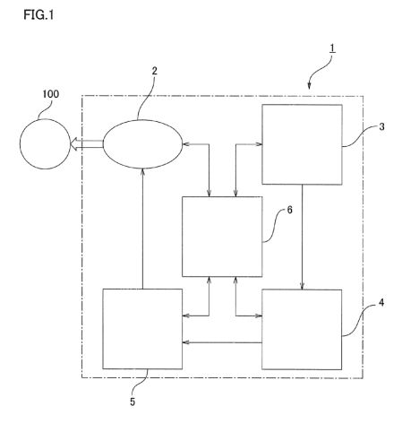
**FIG. 2 is a schematic block diagram showing the power generator
of FIG. 1;**
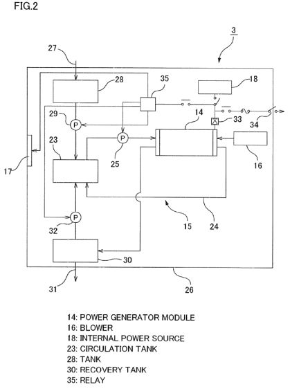
**FIG. 3 is a perspective view showing a power generator module
of the power generator of FIG. 2;**
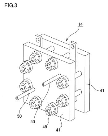
**FIG. 4 is an exploded perspective view showing the power
generator module of FIG. 3;**
**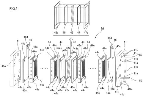**
**FIG. 5 is a perspective view showing the partition plate of
FIG. 4;**
**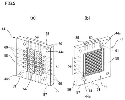**
**FIG. 6 is a diagram showing the flow of liquid fuel; and**
**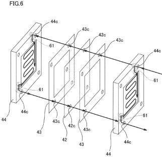**
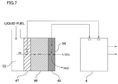
**FIG. 7 is a diagram showing the principle of generating
power in a power generator module.**
**BEST MODE FOR CARRYING OUT THE INVENTION**
Embodiments will now be described with reference to drawings for a
case in which the drive unit of the present invention is adopted
as a drive unit for a hydraulic working machine.
(Overall Structure)
FIG. 1 is a schematic block diagram of a drive unit for a
hydraulic pump. The drive unit 1 of the present example is a unit
for driving, for example, the hydraulic pump 100 of a backhoe or
other hydraulic construction working machine, and is provided with
an electric motor 2, a power generator 3 for supplying power to
the electric motor 2, and a battery 4 for storing the electric
current generated by the power generator 3. Power is supplied to
the electric motor 2 via a capacitor 5. The parts 2, 3, 4, 5 are
drivably controlled by a controller 6. The controller 6 is usually
constructed as a part of a controller for drivably controlling a
working machine on which the drive unit 1 is mounted.
FIG. 2 is a schematic block diagram showing the power generator 3.
The power generator 3 comprises a power generator module 14, a
fuel circulation system 15 for supplying liquid fuel for hydrogen
generation to the power generator module 14, a blower 16 for
supplying air (oxygen) to the power generator module 14, a cooling
fan 17 for cooling the interior of the generator, and an internal
power source 18 for driving the blower 16, the cooling fan 17, and
the pump of the fuel circulation system 15.
The liquid fuel is a fuel having high hydrogen generation
efficiency and can be a product obtained by dissolving 2 to 5 wt %
organic material in 95 to 98 wt % purified water. Purified oil of
citrus fruits or other plants, fermented alcohol from corn or
other grains, or the like may be used as the organic material. A
liquid fuel (trade name: Zumie fuel) manufactured and sold by the
applicant of the present application is particularly preferred.
The fuel circulation system 15 of the power generator 3 comprises
a circulation tank 23, a fuel circulation circuit 24 for
circulating the liquid fuel stored in the circulation tank 23 via
the power generator module 14, and a circulation pump 25 for
circulating the liquid fuel along the fuel circulation circuit 24.
Also provided is a main tank 28 capable of supplying liquid fuel
through an injection port 27 positioned in a generator housing 26.
When the amount of liquid fuel inside the circulation tank 23 is
equal to or less than a prescribed amount, a supply pump 29 is
driven, and the liquid fuel is replenished from the main tank 28
into the circulation tank 23.
The fuel circulation system 15 is provided with a recovery tank
30, and the liquid fuel recovered along with the air from the
power generator module 14 is collected in the recovery tank 30.
The liquid fuel collected in the recovery tank 30 is discharged as
needed through a water discharge outlet 31 positioned in the
generator housing 26. Furthermore, the liquid fuel recovered in
the recovery tank 30 can be returned to the circulation tank 23 by
a supply pump 32.
The DC current generated by the power generator module 14 is
outputted to the internal power source 18 and the battery 4 via a
rectifier 33. A startup switch 34 is positioned in a circuit for
supplying power to the battery 4, and when the startup switch 34
is switched on, power is supplied from the internal power source
18 to the pumps 25, 29, 32, the blower 16, and the cooling fan 17
via a relay 35, and an operation is started in which these
components are driven. Supply of generated current to the battery
4 is started after the power generation of the power generator
module 14 is stabilized.
**(Power Generation Module)**
FIG. 3 is a perspective view showing the power generation module
14, FIG. 4 is an exploded perspective view of the power generation
module 14, FIG. 5 is a perspective view showing the partition
plate, and FIG. 6 is a schematic view showing the flow of a liquid
fuel. The power generation module 14 is provided with the pair of
collection plates 45, a plurality of partition plates 44, and a
plurality of electrode assemblies 42. The electrode assembly 42
has a configuration in which an anode-side electrode plate 47 and
a cathode-side electrode plate 48 are stacked and bonded,
sandwiching an electrolyte film 46. The anode-side electrode plate
47 is a rectangular-shaped electrode plate disposed inside the
interior frame of a rectangular-shaped gasket 47a, the
cathode-side electrode plate 48 also is a rectangular-shaped
electrode plate disposed inside the interior frame of a
rectangular-shaped gasket 48a.
The plurality of electrode assemblies 42 of this configuration are
sandwiched by the partition plates 44 and connected in series. The
electrode assemblies (not shown) that are placed at both ends are
sandwiched by partition plates 44, respectively, and are connected
to the collection plates 45. The rectangular frame-shaped gasket
43 is sandwiched between the electrode assembly 42 and the
partition plates 44 on two sides, respectively, and a fluid-tight
state is formed therebetween. The configuration of these parts
will be described in detail below.
First, the anode-side electrode plate 47 of the electrode assembly
42 is an electrode plate in which platinum is supported on a
sintered compact of particulate powder composed of zeolite, coral
sand, and carbon black. The other cathode-side electrode plate 48
is an electrode plate in which ruthenium is supported on a
sintered compact of particulate powder composed of zeolite, and
carbon black.
Positioning holes 41a, 42a, 43a, 44a pass through and extend in
the thickness direction of the fastening plate 41, the electrode
assembly 42, the gaskets 43, the partition plates 44, and the
collection plates 45 in a pair of corner portions in the diagonal
direction of these components. Positioning pins that are not shown
are passed through these positioning holes 41a through 44a, and
these components are stacked in an aligned state. A plurality of
boltholes 41b are formed in the fastening plates 41, and the
components are integrated in a stacked state by fastening bolts 49
that are passed through the boltholes.
A pair of liquid-fuel supply ports 41c, 42c, 43c, 44c, 45c that
pass through and extend in the thickness direction of one of the
fastening plates 41, the electrode assembly 42, the gaskets 43,
the partition plates 44, and the collection plates 45 is formed in
the other pair of corner portions in the diagonal direction of
these components. The liquid fuel is supplied, e.g., via a
liquid-fuel supply conduit 50 connected to the liquid-fuel supply
ports 41c on an upper side in the exterior surface of one of the
fastening plates 41, and is discharged via a liquid-fuel supply
conduit 50 connected to the liquid-fuel supply ports 41c on a
lower side.
The collection plates 45 have a shape in which a terminal plate
region 45d extends upward in a fixed width from one end of an
upper end surface of the rectangular main plate member. In the
present example, two collection plates 45 have the same shape, and
are disposed with opposite orientations.
Next, the configuration of the partition plates 44 will be
described with reference to FIGS. 5 and 6. One surface of the
partition plate 44 is used as the anode-side surface 51, and in
this case, liquid-fuel supply grooves 52 having a constant depth
extending in a parallel manner at fixed intervals in which the two
ends are in communication are carved inside the exterior
peripheral rectangular frame portion having a constant width. The
other surface of the partition plate 44 is the cathode-side
surface 53, and in this case, air supply grooves 54 having a
constant depth formed in a grid shape are formed inside of the
exterior peripheral rectangular frame portion having the same
constant width.
The same number of air inlet ports 59 is formed in each of the
four peripheral end surfaces 55 through 58 of the partition plates
44, and the air inlet ports 59 are in communication with the air
supply grooves 54 via air passages 60 formed inside the partition
plate. Therefore, outside air is supplied to the air supply
grooves 54 of the partition plates 44 via the air inlet ports 59.
The air supplied to the air supply grooves 54 of the cathode-side
surface 53 of the cathode-side partition plate 44 is supplied to
the cathode-side electrode plate 48 of the electrode junction body
42 facing air supply grooves.
The pair of liquid-fuel supply ports 44c that are formed in the
partition plate 44 are in communication with the liquid-fuel
supply grooves 52 via liquid-fuel passages 61 that are formed
inside the partition plate. Therefore, the liquid fuel that is
supplied from the liquid-fuel supply conduit 50 of the fastening
plate 41 passes through the liquid-fuel supply ports 41c, 45c,
43c, flows into the liquid-fuel supply ports 44c of the partition
plate 44, and from here, passes through the liquid-fuel passages
62 inside the partition plate and is supplied to the liquid-fuel
supply grooves 52. The electrode junction body 42 is stacked in a
fluid-tight state via the gasket 43 on the anode-side surface 51
of the partition plate 44 on which the liquid-fuel supply grooves
52 are formed. Therefore, the liquid-fuel supply grooves 52 are in
an airtight state, and liquid fuel is supplied to the anode-side
electrode plate 47 of the electrode junction body 42 without
leaking to the outside.
At this point, the liquid fuel passes through the liquid-fuel
supply ports 44c, 43c, 42c, 43c that are formed in the partition
plate 44, the gasket 43, the electrode assembly 42, and the other
gasket 43; and is supplied to the liquid-fuel supply port 44c of
the next partition plate 44, as shown in FIG. 6. From here, the
liquid fuel passes into the internal liquid-fuel passage 61, and
is supplied to the liquid-fuel supply grooves 52 of the partition
plate 44. The liquid fuel that flows down to the liquid-fuel
supply grooves 52 of the partition plate 44 passes through the
internal liquid-fuel passage 61, is discharged to the other
liquid-fuel supply port 44c, passes therefrom through the
liquid-fuel supply ports 43c, 42c, 43c, 44c, and is discharged to
the exterior.
In a power generation module 14 of this configuration, the number
of electrode assemblies 42 sandwiched between partition plates 44
and gaskets 43 and connected in series may be increased, whereby
power-generating capacity can be readily increased.
The power generation module 14 generates power by an
electrochemical reaction between a liquid fuel and a catalyst, and
is substantially equivalent to an ordinary fuel cell. In other
words, when liquid fuel is supplied to the anode-side electrode
plate 47 (the fuel electrode), the fuel is electrolyzed and
hydrogen and oxygen are produced, the hydrogen is divided into
hydrogen ions and negative electrons by an electrochemical
reaction, as shown in FIG. 7. Since hydrogen releases an electron
in the reaction, the reaction is an oxidizing reaction. The
generated hydrogen ions pass through the electrolyte film 46
(catalyst) of the electrode assembly 42 and migrate to the
cathode-side electrode plate 48 (oxygen electrode). The
electrolyte film 46 is permeable to ions but blocks electrons, and
the negative electrons are therefore removed to the exterior via
the collection plate 45 of the anode side. On the other hand, air
is fed into the cathode-side electrode plate 48 (oxygen
electrode). Therefore, the hydrogen ions supplied along the
electrolyte film 46 and electrons supplied from the exterior via
the collection plate 45 undergo a reductive reaction, and water is
produced. Power is produced thereby. The produced water is
recovered together with air in the recovery tank 30 (see FIG. 2).
The drive unit 1 of the present embodiment as constituted above is
assembled in a hydraulic working machine so as to drive the
hydraulic pump thereof, whereby realizing a low noise working
machine. Such a working machine is suited for use in construction
work during midnight at a residential or other place, and is also
suited for use in work inside a place such as a house, a tunnel or
the like where ventilation is insufficient.
**Other Embodiments**
The drive unit of the present invention can be used as that for
driving the electric motor of an electric vehicle. In this case,
the drive unit may have the same structure as that shown in FIG.
1, and the output of the electric motor 2 is transferred to a
power transmission mechanism that transfers the power to the drive
shaft of the drive wheels of the electric vehicle.
As mentioned above, the drive unit according to the present
invention is able to use the power generator that has high
power-generation efficiency, is small and has high power output in
comparison with the conventional fuel batteries, and to drive an
electric motor for driving a hydraulic pump, an electric vehicle
and other machines. Hence, it is possible to realize a drive unit
that is suited for use in the hydraulic pump and that has a low
noise level and does not emit exhaust gas. It is also possible to
realize a drive unit suited in use for driving the electric motor.
---
**SEPARATOR OF LIQUID FUEL TYPE FUEL CELL**
**JP2010113918 (A)**
---