Ronald HATTON -- Gadgetman Groove

[rexresearch.com](../index.htm)
---
Ronald HATTON
Gadgetman Groove
---
---
Ron Hatton
Gadgetman Technologies, LLC
1417 N. Ananea St.
Mesa, Arizona, USA
Tel: (866)GO-GADGET ext.711
E-mail:
Gadgetman(at)GadgetmanGroove.com
Mobile: 307-413-0342
The Gadgetman Groove is new technology proven to reduce emissions
and increase power using the simple science of aerodynamics. By
increasing the turbulence within the intake manifold, we are
improving the combustion of your gasoline. The natural result is
more power being delivered to the top of your piston resulting in
reduced emissions, more horsepower, better torque and (in many
cases) improved mileage as well.
---
---
[**http://co2u.info/?page\_id=47128**](http://co2u.info/?page_id=47128)
**Gadgetman Groove = Snake Oil Science = Hoax
~ Scam = Fraud by Ron Hatton & Dr. John Balachandra CSU
Sacramento**
**by** **Dr. Bruce A. Kershaw**
The Victims of Scams are those who do not comprehend the Real
Science ~ and in many cases those committing the scam do not
comprehend the Real Science as the Snake Oil Salesman does not ~
know ~ what is in the bottle he is trying to sell you .adding
Grooves inside a Throttle Body can not change Gravity because
Gravity is caused by the Earth rotating around the variable Sun at
18 miles per second while spinning at 1000 miles per hour at the
Equator while rotating at 1? per hour at the Poles of this Carbon
based Earth
and as the Moon continues to move very slowly further away from
this Earth the speed the Earth is spinning continues to slow
do causing less Gravity so if you want to get half way
around the world faster go in the opposite direction the earth is
rotating and if you are Drag Racing you will have a faster time
racing east than racing west while every Quarter mile is Dialed
In ~ tuned ~ differently based on Gravity at the location of
the Race Track as gravity is less the higher you go in elevation
and the same for oxygen levels with every ~ Dial In ~ fine tuning
of the Engine based on Gravity, Barometric Pressure, Oxygen level
in the air, Air Density, Air Temperature, Air Humidity, Fuel
Temperature, Track Temperature and the Temperament of the Driver
on that day, and then you let the 10,000 Horses run down the
Quarter mile Track taking about 4 seconds as the variables change
every run and in the car you drive ~ in real physics and chemistry
you can not change 14.7 to 1 ~ air to fuel ratio = mixture
controlled by an On Board Computer based on input information from
many sensors while you can increase mileage by making a car
smaller and lighter with a smaller engine but you still can not
change 14.7 to 1 air to fuel ratio = mixture on todays Internal
Combustion Engine for the engine to run properly with out damaging
the engine while you can make ~ very small ~ increases in fuel
efficiency by ~ { ( reducing ) } ~ air intake Turbulence and
Restriction and by reducing exhaust outlet Turbulence and
Restriction and by making minor changes in engine tuning
parameters with changes in the on board computer program and by
making minor mechanical changes like Compression Ratio and Valve
Timing by changing the Cam Shaft to one with less valve overlap
but you can not change 14.7 to 1 air to fuel mixture you can
replace worn out spark-plugs and see an increase in MPG as much as
10 to 15 % you can do a fuel Injector cleaning once a year and
maintain your engines fuel efficiency and in most cases if you use
a higher octane fuel you will see an increase in Fuel efficiency
while putting Grooves in your Throttle Body providing un-wanted
Erratic air turbulence in the air intake system of your cars
engine where you want to ~ { reduce } ~ air turbulence can only do
Harm and zero good but you can not change the 14.7 to 1 air to
fuel ratio controlled by the On Board Computer under all driving
conditions
Adding grooves in the Throttle Body can not change or over ride
real Physics and Chemistry and or over ride the On Board Computer
and all the Input Sensors
You can not Double or Triple the miles per gallon of your car by
adding un-wanted turbulence in the intake manifold by placing
grooves in the Throttle Body of your cars engine ~ not in real
science
To: energyscienceconference.com ... energyscienceforum.com ...
energeticforum.com ... peswiki.com ... speedtalk.com ...
www.s10forum.com ... www.rexresearch.com ... and all the other
online Energy and Automotive websites promoting theWorld Wide Hoax
Scam the ~ Gagetman Groove ~ by Ron Hatton creating ~ un-wanted
erratic air turbulence ~ in the air intake system doing only harm
and zero good as you want to reduce turbulence not increase
turbulence in the air intake system just as Plugging off the PCV
system can do only harm to your engine and zero good as explained
on page 6 and is test proven Moron Science by the proven Criminal
and Scam Artist Ron Hatton and if Ron Plugged off your PCV system
as this is an Emission Control Device Ron is then subject to a
$40,000 fine as this traps heat and Gas Vapor in the crank case
turning your crankcase into a very test proven Bomb while doing
very proven harm in many other ways to your cars engine as I
explain in further detail later on page 6 in this Technical
Science Review Statement for ~ some ~ of us reality is make
believe while scam Science is far to easy to prove is a scam but
only if you do in fact comprehend the science while those who do
not comprehend the science are those being Scammed Brainwashed
Stupidity by those who failed High School Auto Shop does not
Debunk 57 years of very test proven Automotive Science or 100 plus
years of very proven Physics and Chemistry ignored by those who
failed High School Auto Shop selling this Hoax Scam to the Public
who are now in the community of Helena Montana selling their scam
science -- In response to an email May 12,2017 from Jesse Denson,
Ridgely ~ Tennessee who has proven to me in his emails to me he is
a test proven Moron in Science who truly believes in the snake oil
scam he is selling as Jesse states in his last email to me that I
am the Fraud as he does not comprehend the knowledge that has
debunk his Snake Oil Scam science -- with a reminder to all -- all
communications are forwarded to the Lewis & Clark
Sheriffs Department, Helena ~ Montana
Jesse, putting grooves in a throttle body can not change
Gravitybasic engine vacuum is 21? at sea level and 16? at 4000
feet above sea level and adding Grooves in a Throttle Body can not
change that fact while there are many ways to change
positive and negative pressure in the air intake system of your
internal combustion engine and adding grooves to your throttle
body is not one of them as this will only provide un-wanted air
turbulence that is mixing with zero fuel providing an
un-wanted un-even flow of air to the combustion chambers
causing an un-wanted un-even air to fuel mixture causing some
cylinder to run leaner and some cylinders to run richer than
others as the amount of fuel going to each of the cylinders is the
same and controlled only by the On-Board Computer and not by the
un-wanted added grooves in the throttle body that can not
over-ride the On-Board Computer and or Input Sensors and or Output
Actuators while the added Grooves are causing un-wanted un-even
balance of power from the engine while over time can and
will cause damage to your engine while plugging off the PCV vacuum
port will do only harm to engine and zero good and if you do this
to some elses car engine you are subject to a Fine by the
U.S EPA of $40,000 per emission control device altercation
and or State EPA for altering an emission control device as
Regulations vary from state to state as you support this ~ Test
Proven Moron Lunatic Scam Science ~ proving ~ you failed High
School Auto Shop ~ as ~ Ron Hatton truly believes his Moron Scam
Science is real and works and is not a Scam making Ron Hatton a
Pathological Snake Oil Salesman who does not know what is in the
bottle he is trying to sell you who based on his Criminal History
Methamphetamine use, his Public Letters posted online when
in Jail his Bail Jumping and Bad Check writing and his Snake Oil
Scam crimes of today and his Lunatic email letters to me Ron
should be back in a Jailor ~ Mental Institution -- as Ron
continues to sell his Fraudulent Pathological Make Believe Fantasy
Science Fiction to the World but only to thoes who do not
comprehend the science and want to just Believe too just as Ron
does not comprehend the knowledge that has more than Debunk his
very true belief in his very Lunatic Science as real science is
Questioned not believed while an energy science organization I
have now communicated with informed me they had Ron modify a
number of their vehicles -- they did not say how many vehicles --
and none of them showed any mileage gains while Ron has very much
proven to me in his emails to me he is a Paranoid Lunatic Conman
while I am told my biggest fault in life is my Cruel Honesty
So Jesse, bring me a car you tripled the Gas mileage on and we
will do a reverse test or a Car that Ron Preaches to the world
went from 18 MPG to 108 MPG that is 6 times the MPG and would be a
14.6 to 1 air to fuel mixture to a 80 to 1 air to fuel mixture
with better performance debunking 100 plus years of very test
proven Physics and Chemistry as an 80 to 1 air to fuel mixture
will produce zero energy and can not push a cylinder piston
downward in a combustion chamber and anything beyond a 15 to 1 Air
to fuel mixture will lose power not gain power and will misfire
and produce zero energy and so doubling the MPG would be a 30 to 1
Air to fuel mixture and will produce zero power in a combustion
chamber and is high School Auto shop Science you and Ron do not
comprehend as true belief does not debunk 100 plus years of very
proven Physics and Chemistry.
Regards
Dr. Bruce A. Kershaw
---
Pure Energy Systems News
December 7, 2009
Gadgetman Groove
by
Sterling D. Allan
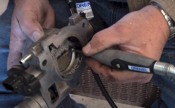
Ron Hatton ("Gadgetman") says he has come up with a simple way to
significantly improve the combustion in normally-aspirated
gasoline engines. All he does is use a Dremel tool to cut a groove
of specific dimensions, around 1/8 inch deep, in the throttle
body. The modification takes about an hour and is reversible
through epoxy. It shouldn't affect the vehicle's warranty.
Somehow, the air turbulence that is set up by that groove has the
effect of increasing horsepower, torque, and mileage, while
decreasing emissions. Perhaps it is another manifestation of the
famous Schauberger effect.
Gadgetman
groove simulation of air passing by the grooves, creating
turbulence

The mileage increase is typically between 25 and 35 percent,
though some reports are much higher than that; and a few show
little, if any change. So far, it seems that older cars achieve
better improvement than newer cars, because the computerized
controls of the newer cars usually tend to work against the
effect. Ron said that approximately 85% of the vehicles that have
been modified with this groove have had mileage gains in excess of
20%. So far, the best results apparently have been found on 1996 -
2004 Fords.
Ron says he has filed for patents on the design as well as on the
bits; and that he is training dealers/installers from all over the
globe to make this modification. He himself has modified around
200 engines.
On Dec. 2, 2009, I had one of Ron's dealers in Salt Lake City,
Dave Richardson, do the modification on my Dodge Caravan, 2005;
3.3L, V6. It took him about 55 minutes. I noticed a definite kick
in acceleration when first starting out, though that could be a
function of the more immediate air volume coming in due to the
grooves.
Dave showed me his before and after dynamometer test results from
the modification he made on his own truck. It shows a 15
horsepower increase and 8 foot-pounds of torque increase across
the board.
On Dec. 5, 2009, I finished the first full tank of gas since the
installation, and calculated that my mileage for that 392-mile
stretch, using 16.6 gallons, came to 23.6 mpg. During that time,
most of our travel was highway, but some (approximately 15%) was
city driving. According to FuelEconomy.gov, my vehicle typically
gets 16 mpg city, and 23 mpg highway. (With my recent move, I've
misplaced the baseline data I accumulated last summer.) So our
improvement in comparison to the average rating, was roughly in
the region of 10% -- nothing to brag about, but still significant
and worth while.
On Dec. 10, I finished my second full tank, travelling 359 mile
(@119897 miles) on 16.883 gal, for 21.26 mpg, which is lower than
the 23 mpg rating according to the govt. site; but mileage is
typically lower in cold temperatures; and it's been very cold here
during the relevant time (staying below freezing most of the
time).
Dec. 23; @119266 miles; 369 miles on 16.592 gal = 22.2 mpg.
Dec. 25; @119620 miles; 354 miles on 14.153 gal = 25.0 mpg.
(probably early shut-off error)
One thing that concerns me about the modification is that I don't
have much wiggle room when I first accelerating. Most people would
be delighted with the punch you get when you press the pedal.
However, I'm concerned that if I'm on slick roads and I need to
accelerate gingerly, that I won't have nearly as much control of
speed-up, making it easier to spin-out. So for me, that is not a
year-round benefit.
For me, I attribute that early punch in power to the fact that a
little movement of the throttle early on is opening it to a large
opening due to the groove, where before the opening of the
throttle flow was much more gradual. So I don't attribute it to
"more horsepower" but to "more airflow". I'd have to take the car
to a dyno with before/after to document horsepower.
One thing that is admirable about the Gadgetman site is that it
publishes all mileage reports, including the mediocre ones, as
well as a few that actually saw their mileage get worse.
At this early phase, they are still anxious to increase their
database; and they are still making decisions about how much to
charge for the modification; so you are likely to be able to get a
good deal on your install. Dave did mine for free. He personally
wants to accumulate more data before going all out on this
venture.
The installations come with a satisfaction guarantee.
FROM RON HATTON, GADGETMAN Feb 28, 2011
After much prompting, I have recorded a video that explains the
science employed to generate the continued reports of increased
performance. The video appears here:
[**http://www.youtube.com/watch?v=eHV-ANmN0ns**](http://www.youtube.com/watch?v=eHV-ANmN0ns)
I have now modified almost 700 engines, and have learned the
removal of the PCV valve to be a critical part of the application
of The Gadgetman Groove. What happens is the PCV valve represents
as a direct vacuum leak, reducing the pressure wave the groove
creates. The crankcase remains vented, although only with passive
vacuum rather than full dynamic vacuum. This enhances the results
in every case.
The price point for this modification by professionals is $350.
Ron encourages all "G-men" to charge $100 when they first start
out, then $250 as the demand increases and their skill level
improves, then $350. I thought that was too high, for a task that
takes 1 hour, but Ron pointed out a few things.
1. At that price, the typical driver is going to see
a return on investment in between 6-12 months due to the usual
mileage improvements seen.
2. The install lasts the duration of the vehicle.
3. At first, he was charging $100, but the lower
price gives a low value impression. His sales went up and
referrals increased when he bumped his price to $250.
4. The pros say that each added horse added to the
engine's HP is worth $100 each. The average HP gain is in the
region of 15.
5. $350 is so the shops that are signing on have a
base. The shops Ron has approached have been excited about the
price point, and have told him they believe it to be fair.
6. There are start-up licensing and tooling costs for
installers to be recouped.
Older, carbureted engines are usually more involved and will thus
cost more to modify.
ADDENDUM BY GADGETMAN
The pricing is established based on the number and style of ports
through which the air passes. The overwhelming majority are
single, rounded port systems. For these, the modification price is
$350, including single barrel carbs. For dual and oval ports MPFI
systems, as well as 2 and 4 barrel carburetors, the cost is $500.
Most carburetors accept the modification with great ease. Best
results to date (Feb, 2011) have been found in the Edelbrocks and
Holley's, with rejetting advised to maximize fuel efficiency.
Only certain older carbs are virtually impossible to modify. In
particular, Quadrajets present the greatest difficulty. This is
due to the way the throttle assembly was engineered, leaving too
little room to install The Gadgetman Groove.
Additionally, vehicles NOT suited for this modification are: 1)
2007 and later Excalades-Computer acceptance issues 2) 454 TBI
(Throttle Body Injected) General Motors-idle air passage
interference 3) Certain (as yet undefined) 2004 and later GM
products-a whistle is generated, making some drivers
uncomfortable. 4) All engines with "Constant Velocity" throttles.
---
WO 2010148153
THROTTLE BODY AND A METHOD TO
MODIFY A THROTTLE BODY
2010-12-23
Inventor(s): HATTON RONALD E + (HATTON, RONALD,
E)
Classification: - international: F02D9/02;
F02D9/08; F02D9/10 - European: F02D9/10H2
FIELD OF THE INVENTION
[0001] This invention generally relates to throttle bodies of
machines, mixing valves and engines and a method of modifying
throttle bodies. More specifically this invention relates to
incorporation of at least one groove located inside a fluid
passageway of the throttle body that improves fluid turbulence in
a machine such an internal combustion engine. For example, in an
internal combustion engine the performance is enhanced such as
increased gas mileage, lower fuel emissions, carbon foot print
and/or increased horse power and torque.
BACKGROUND
[0002] Many machines, such as internal combustion engines, require
precise fluid mixtures, such as air and gasoline, in order to
properly run. In this instance, throttle bodies are designed to
control fluid flow, such as airflow and/or air-fuel mixtures flow,
to the cylinders of an engine. In order to control the fluid flow
that reaches the cylinders, the throttle body includes at least
one throttle plate attached to a central axis or; for example, a
central axis shaft (also known as a throttle shaft) such that the
throttle plate is located within a fluid passageway (sometimes
known as a throttle bore or duct), or proximal to an end of the
fluid passageway. With rotation of the central axis, the throttle
plate is able to selectively obstruct flow through the fluid
passageway. More specifically, the throttle plate is able to
rotate with respect to the fluid passageway in order to adjust the
cross-sectional area of the fluid passageway that is not
obstructed by the plates (the "effective area"), thus controlling
the amount of fluid, such as airflow, that is permitted to flow
through the fluid passageway.
[0003] In order to control the effective area, the throttle plate
is sized and shaped to approximate the cross-sectional area of the
fluid passageway so as to substantially or completely obstruct the
fluid passageway when the throttle plate is perpendicular to the
airflow (the "closed position"). Typically, the throttle plate has
a minimal thickness in order to substantially not obstruct the
fluid passageway when the throttle plate is angled such that a
throttle plate is not substantially perpendicular to the airflow
(the "open position").
[0004] When the engine is idling, the throttle plate is therefore
in the closed position since only a little air is needed to mix
with the small amount of fuel being injected into the engine. On
the other hand, if the engine is operating at a speed higher than
idle, then more air is needed to mix with the increased amount of
fuel being provided to the engine. At speeds higher than idle, the
throttle plate is therefore in an open position of a varying angle
with respect to the airflow, the angle varying with the engine's
air requirements.
[0005] In order to completely or substantially obstruct the fluid
passageway when the throttle plate is the closed position, it is
desirable for the throttle plate to be precisely sized and
accurately located within the fluid passageway.
[0006] Throttle body spacing blocks are well known in the prior
art and are frequently found in the automotive part after-market.
Examples include the AFE Silver Bullet Spacer, Airaid Power Aid
Spacer , Helix Power Tower Spacer, and Jet Power-Flow Spacers as
discussed in the provisional patent applications incorporated by
reference herein.
[0007] These after-market throttle body spacing blocks typically
claim to improve automotive performance. Generally, the throttle
body spacing blocks separate the existing throttle body, throttle
body injection unit and/or carburetor from the intake manifold of
an internal combustion engine found in automobiles. This
separation creates increased space that it is posited by the
manufactures of the throttle body spacing blocks to increase the
air velocity prior to entering the combustion chamber of the
engine. Under such a supposition, the increased air velocity would
serve to improve the efficiency of the internal fuel combustion.
Generally, throttle body spacing blocks are known to consist
basically of obvious structural configurations.
[0008] In addition, modifications of the internal bore of throttle
body spacers are known such as US Patent no. 6,338,335 issued to
Patterson, et on January 15, 2002 and entitled "Throttle body
spacing block with continuously grooved aperture(s) for internal
combustion engines" which incorporated by reference in its
entirety herein. US Patent no. 6,338,335 teaches the use of a
throttle body spacing block having a single, continuous thread
pitch groove starting at the inlet opening and stopping at the
outlet opening.
[0009] One disadvantage of the throttle body spacing blocks is
that they require the insertion of an additional element into the
air intake system.
[0010] Another disadvantage of the throttle body spacing blocks is
that they generally do not work with the throttle body plate. It
is believed that previous efforts created incomplete, partial,
destructive, or no waveforms as applied primarily in the form of
throttle body spacing blocks. This invention is believed to
overcome these disadvantages by creating a more complete waveform
that, it is believed, passes through the intake.
[0011] The present invention overcomes these disadvantages by
modification of the throttle body itself for any and all internal
combustion engines and is not limited to automobiles. While not
being limited to any theory, it is believed that the invention
also overcome these disadvantages by creating a more complete
waveform that, it is believed, passes through the intake. As there
is need for an improved throttle body modification that can
increase gas mileage, increase horsepower, increase torque, reduce
carbon footprint and/or reduce emissions, it is believed that the
present invention substantially fulfills these needs.
SUMMARY
[0012] One embodiment of the present invention relates to a
throttle body comprising a housing having a throttle body wall
including an outside surface and an inside surface wherein the
inside surface forms a fluid passageway leading from an open end
to a discharge end of the housing; a throttle plate located in the
fluid passageway and having a front surface facing the open end of
the fluid passageway and back surface on the opposite side wherein
the throttle plate is coupled to the housing by a central axis and
wherein the throttle plate may be rotated from a closed position
to an open position; and at least one groove in the throttle body
side wall near to the throttle plate wherein the at least one
groove modifies fluid flow though the throttle body in cooperation
with the throttle plate movement from the closed position.
[0013] Preferably, the at least one groove is located near the
front surface of the throttle plate that rotates toward the at
least one groove when the throttle plate is moved from the closed
position. Also preferably, the at least one groove is located near
the back surface of the throttle plate that rotates toward the at
least one groove when the throttle plate is moved from the closed
position. In another preferable manner, the at least one groove
has a depth and a width of one half thickness of the throttle body
wall and more preferably the at least one groove forms a curve
from the depth to the groove edge furthest from the throttle plate
when the throttle plate is in a closed position. In yet another
preferable embodiments, the at least one groove is a hemispherical
cut or a compound cut.
[0014] An additional preferable embodiment includes at least one
groove in the throttle body side wall that is perpendicular to
direction defined by fluid flow between the open end and the
discharge end, more preferably, the at least one groove covers at
least one quarter of the inside surface, and most preferably, the
at least one groove extends in substantially one-half of the
inside surface bounded between the plane formed by a longitudinal
axis, of the fluid passageway, and the central axis.
[0015] Another embodiment of the invention includes a method of
creating a modified throttle body comprising the step of creating
at least one groove in an inside surface of a housing having a
fluid passageway and a throttle plate located in the fluid
passageway and coupled to the housing by a central axis wherein
the at least one groove is located near the throttle plate.
Likewise, an embodiment of the invention includes a method of
creating or enhancing wave pulses in throttle body comprising the
step of creating at least one groove in an inside surface of a
housing having a fluid passageway and a throttle plate located in
the fluid passageway and coupled to the housing by a central axis
wherein the at least one groove is located near the throttle
plate.
[0016] Yet another embodiment of the invention includes a method
of reducing the carbon footprint of an engine comprising the step
of creating at least one groove in an inside surface of a housing
having a fluid passageway and a throttle plate located in the
fluid passageway and coupled to the housing by a central axis
wherein the at least one groove is located near the throttle
plate. [0017] An additional embodiment of the invention includes a
method of creating enhanced movement of fluids comprising the step
of creating at least one groove in an inside surface of a housing
having a fluid passageway and a throttle plate located in the
fluid passageway and coupled to the housing by a central axis
wherein the at least one groove is located near the throttle
plate.
[0018] A further embodiment of the invention includes a bit for
creating at least one groove in a throttle body comprising a shank
to couple to a high speed rotary tool, and a cutting head having a
hemispherical portion nearest the shank end terminating in a flat
surface or, alternatively, a bit creating at least one groove in a
throttle body comprising a shank to couple to a high speed rotary
tool, and a cutting head having a hemispherical end furthest from
the shank and having an oblique angle from the shank to the
equator of the cutting head
BRIEF DESCRIPTION OF THE DRAWINGS
FIGURE 1 shows a standard
configuration of a stock throttle body with the linkage omitted
for visibility.
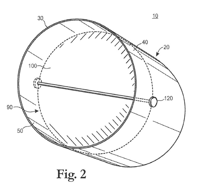
FIGURE 2 shows an oblique
view of throttle plate in throttle body where the throttle plate
is on a central axis, specifically a central axis shaft, so that
throttle plate rotates to open when an accelerator is depressed.
FIGURE 3 shows a side view
diagram of a standard configuration of a stock throttle body with
a throttle seat and a preferred direction of rotation.
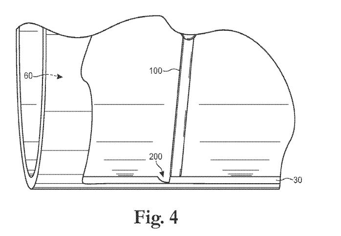
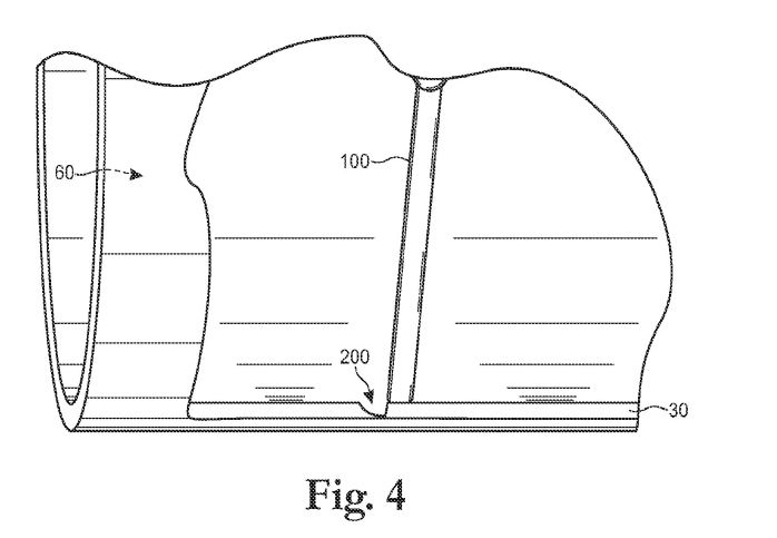
FIGURE 4 shows a partial
cross-sectional side view diagram of a preferred embodiment of an
inferior groove placement in relationship to a throttle plate in a
standard configuration of a stock throttle body.
FIGURE 5 shows a partial
cross-sectional side view diagram of a preferred embodiment of a
superior groove placement in relationship to a throttle plate in a
standard configuration of a stock throttle body.
FIGURE 6 shows a
cross-sectional side view diagram of one possible theory of the
invention when a preferred embodiment of the at least one groove
placement in relationship to throttle plate in a throttle body
open at 10% of acceleration.
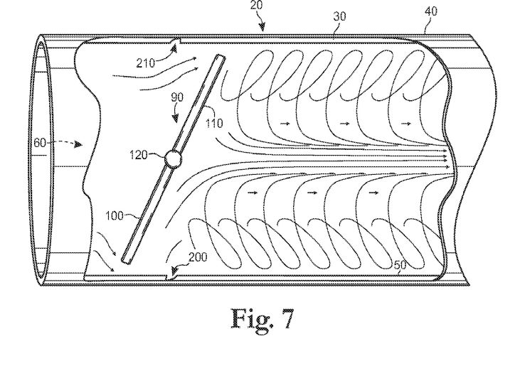
FIGURE 7 shows a
cross-sectional side view diagram of one possible theory of the
invention of a toroidal shape pressure wave of a preferred
embodiment of the at least one groove placement in relationship to
throttle plate in a throttle body.
FIGURE 8 shows a
cross-sectional side view diagram of one possible theory of the
invention when a preferred embodiment of the at least one groove
placement in relationship to throttle plate in a throttle body
open at 85% of acceleration.
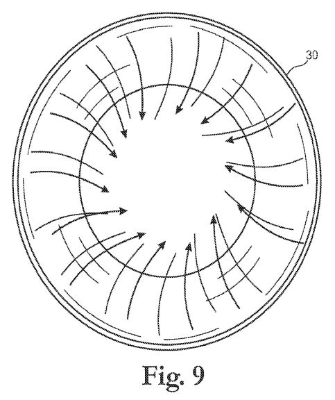
FIGURE 9 shows an open end
view diagram of one possible theory of the fluid movement of
preferred embodiment of the invention at lower engine speeds.
FIGURE 10 shows an open
end view diagram of one possible theory of the fluid movement of
preferred embodiment of the invention at higher engine speeds.
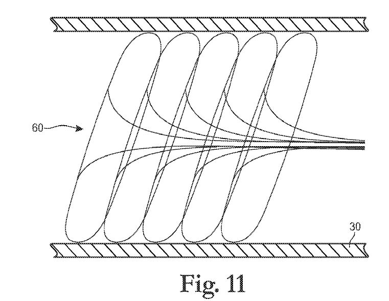
FIGURE 11 shows a
cross-sectional side view diagram of one possible theory of the
fluid movement of a wave pattern of low pressure pulses of a
preferred embodiment of the invention at higher engine speeds.
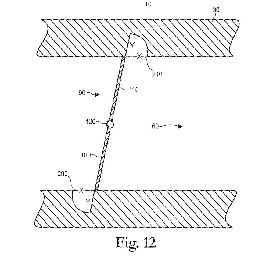
FIGURE 12 shows a side
view diagram of groove cuts in the throttle body wall.
FIGURE 13 a, 13 b and 13 c
shows preferred embodiments of one configuration of the bits of
the invention. [0032] FIGURE 14 a, 14 b and 14 c shows another
preferred embodiments of one configuration of the bits of the
invention.
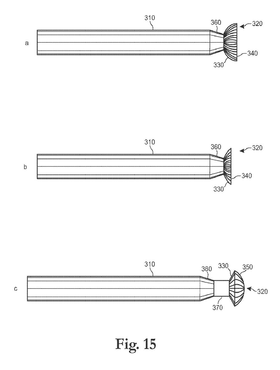
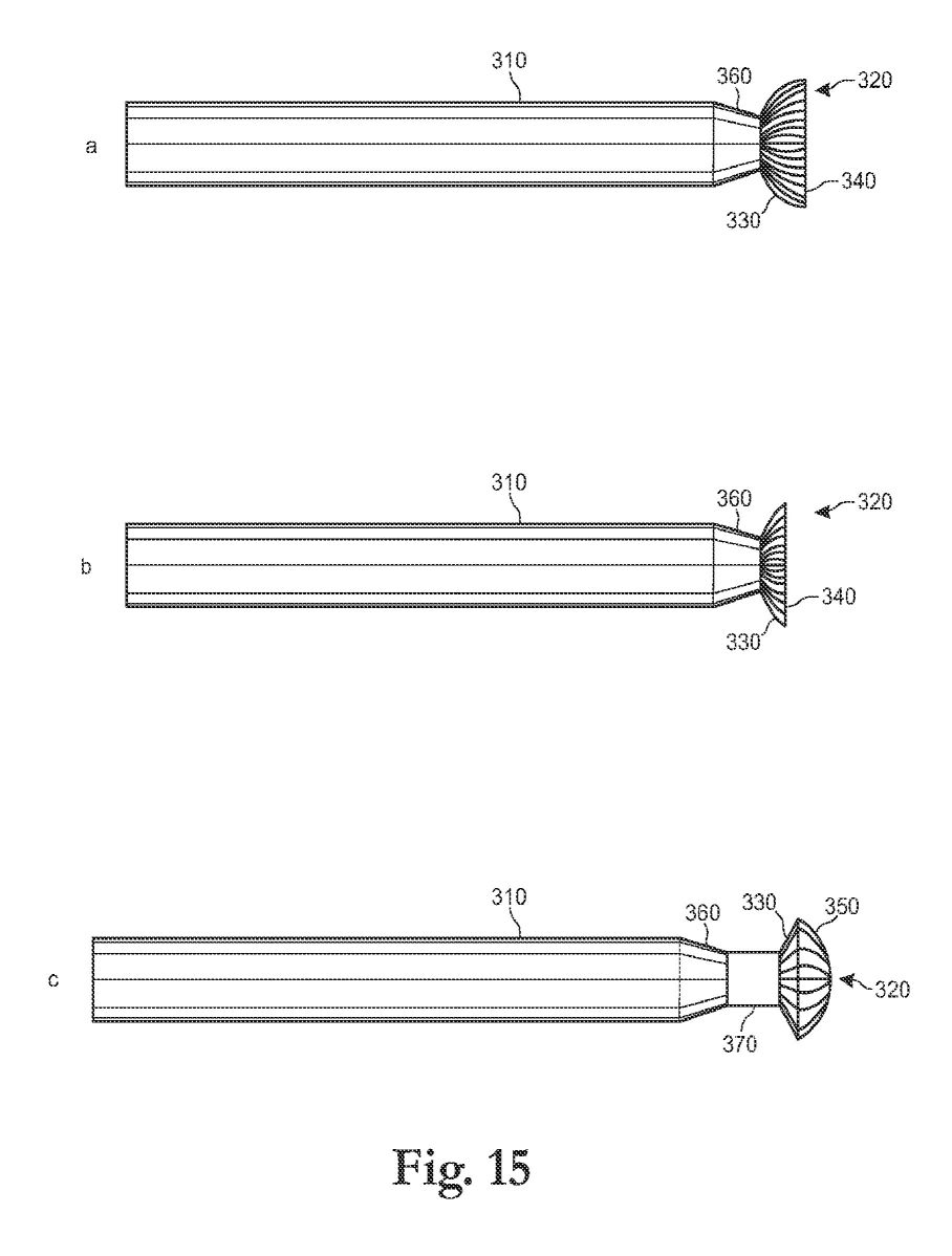
FIGURE 15 a, 15 b and 15 c
shows another preferred embodiments of one configuration of the
bits of the invention.
DESCRIPTION
[0034] In a preferred embodiment of the invention, the aerodynamic
design of throttle bodies are changed (or modified) to, what is
believed, create higher vaporization of fuels, reduce emissions
and reduce fuel consumption. While not being limited to its
proposed theory, it is believed that the invention causes the
throttle to be more responsive at lower speed operation. The
preferred invention is believed to create a pressure wave at the
throttle plate and additional turbulence such that it increases
vaporization and blending of liquid in the system to which it is
applied possibly like those proposed in figures 6 through 11. For
example, it is believed that the invention causes liquids to
vaporize (for example, fuels including but not limited to
gasoline) enabling its use in the internal combustion engine such
as normally aspirated gasoline engines to achieve better explosive
properties and mileage (i.e. efficiency) and performance gains
including torque at wider ranges than any previous modifications
or inventions.
[0035] A standard configuration of a stock throttle body 10 (with
the linkage omitted for visibility) is shown in Figure 1. The
throttle body 10 includes a housing 20 having athrottle body wall
30. The throttle body wall 30 has an outside surface 40 and inside
surface 50 wherein the inside surface 50 defines the fluid
passageway 60 and the fluid passage 60 has a longitudinal axis 62
(see figure 11). Preferably the housing 20 is cylindrical, but
maybe of any geometry that will work with fluid flow. The housing
also includes an open end 70 and a discharge end 80 so that the
fluid moves from the open end 70 to the discharge end 80. Further,
the term fluid includes any liquid or vapor such as air and the
term throttle body means any device used for metering fluids.
Housings for throttle bodies are well known and are typically made
of metal or other suitable materials.
[0036] Also as shown in Figures 1 and 2, the throttle body 10 also
includes a throttle plate 90 located in the fluid passageway 60
and having a front surface 100 facing the open end of the fluid
passageway 60 and having a back surface 110 on the opposite side
from the front surface 100. Throttle plates are well known and are
typically made of thin metal or other suitable materials. As shown
in this embodiment, the throttle plate 90 is coupled to the
housing using a central axis 120. While the central axis may be
coupled by any means to the housing such as pins, shaft or other
mechanical or magnetic structure, preferably the central axis 120
is a central axis shaft and attaches to the throttle plate 90 and
is rotatably (or pivotally) connected to the housing 20. When the
throttle plate 90 is in a closed position, it blocks the passage
of fluid through the fluid passageway 60. Typically, when the
throttle plate 90 is in closed position it forms a fit with a
throttle seat 65. The throttle plate 90 also has an open position
that varies between 0 degrees and 90 degrees with respect to
rotation from the closed position. A throttle plate means any
obstruction in the fluid passageway.
[0037] In a preferred embodiment of the invention, at least one
groove 200 or 210 is created into the throttle body wall 30 as
seen in figures 4 though 8 and 12 wherein created means cut,
molded, machined, formed, or anything that makes a groove in
throttle body wall 30. In one preferred embodiment shown in figure
4, the at least one groove 200 has inferior groove placement (at
the bottom of the housing 20). In another preferred embodiment
shown in figure 5, the at least one groove 210 has inferior groove
placement (at the top of the housing 20). While the invention can
be practiced with one groove, combinations of grooves are also
within the scope of the invention. Further, the at least one
groove preferably includes at least one quarter of the
circumference of the inside surface (i.e. the cylindrical
passageway formed by the inside surface 50), but it is possible
that such a groove need not be continuous and may be combined with
other grooves. More preferably the at least one groove preferably
includes at least one half of the circumference of the inside
surface (i.e. the cylindrical passageway formed by the inside
surface 50), and most preferably, the one half is bounded by a
plane formed by a longitunal axis 300 of the fluid passageway and
the central axis 120. It is, however, preferred as shown in figure
5, to use one groove placed after the throttle plate 90 (that is
placed toward the discharge end when the throttle plate is in the
closed position) and is superiorly placed if the rotation of the
throttle plate 90 is clockwise (if the rotation of the throttle
plate is counter clockwise then inferior placement of the one
groove would be preferred).
[0038] Preferably, the at least one groove 200 or 210 is placed
near to the throttle plate and works cooperatively with the
throttle plate 90 to modify the fluid flow such as enhancing a
pressure wave or toroidal nature of the fluid flow, and, more
preferably, the at least one groove 200 or 210 does not interfere
with the throttle seat 65. Most preferably, the at least one
groove is placed near the position of the throttle plate when the
throttle plate is in idle position such as when an engine is
idling. In a preferred embodiment, the at least one groove 200 or
210 has a depth (y) and a width (x) that are roughly equivalent as
shown in figure 12. In another preferred embodiment, the groove
has the following characteristics x=y and the radius of curvature
(z)(not depicted) is 0.8x. It is believed that the dimensions may
be varied for x, y and z as long as the pressure wave is created
or enhanced. Further, in a preferred embodiment the dimension of x
is 3 millimeters, but the value of x may be varied between 2 mm
and 4 mm. In a most preferred embodiment, the dimension x is
one-half the thickness of the throttle body wall. Preferably, the
groove dimensions are adjusted according to the characteristics of
the individual application as based on the variables of
displacement and intake air speed.
[0039] Preferably, the at least one groove 200 or 210 is
perpendicular to the inside surface, more preferably at least one
groove 200 or 210 is perpendicular to direction defined by fluid
travel from the open end to the discharge end, but most
preferably, the at least one groove 200 or 210 is slightly curved
to match the throttle body plate consistent with an imaginary
slice made through the housing in the plane formed by the throttle
plate 90 when it is in an idle position.
[0040] In a preferred method, the at least one groove may be
created by a hemispherical cut using a bit 300 wherein a bit means
any tool for altering or creating shapes in structures. In another
preferred embodiment, compound cuts may be created by a special
bit or by making one or more additional cuts next to or within a
previous groove.
[0041] While not being bound by any theory suggested herein, it is
believed that the fluid flow is modified by the at least one
groove to create pressure waves and possibly rolling toroidal
pressure waves and that the pressure waves maintain their
integrity of the wave pulse as postulated in figures 6 through 11.
It is believe that this mechanism or one like it provides a method
to increase gas mileage, increase horsepower, increase torque,
reduce emissions and/or reduce the carbon foot print of a machine,
especially an internal combustion engine.
[0041] This invention also includes a method of creating the at
least one groove in the throttle body side wall 30. In a preferred
embodiment the at least one groove 90 may be cut into the throttle
body side wall 30 using a bit 300 described in figures 13 - 15.
Preferably the bit 300 is used with a high speed rotary tool to
cut a groove into the throttle body wall 30 of an existing
throttle body 10 on an engine. In the preferred embodiment, as
throttle bodies differ from engine to engine, different bits may
be used to create the at least one groove. Preferred embodiments
found in figure 13-15 include one or more of the following
elements: a shank 310, a cutting head 320, a hemisphere section
330, a flat surface 340, a oblique angle portion 350, tapered
shank section 360 and/or a reduced shank section 370.
[0042] The preferred embodiments shown in figures 13a, 14a, an 15a
show bits used for a primary cut having a hemispherical portion
terminating in a flat surface which is most preferably a 50
percent cut at the equator of the hemisphere. This bit would be
preferably used for the primary cut on the portion in front of the
throttle body as seen in figure 12 thereby generating the
principal shape for the waveform producing groove. Also,
preferably this bit may be used for the primary cut on the portion
in front of the throttle body as seen in figure 12 when access is
available to the portion of the throttle body.
[0043] The preferred embodiments shown in figures 13b, 14b, and
15b show bits used for a secondary cut having a hemispherical
portion terminating in a flat surface which is most preferably a
60 percent cut. This bit may be preferably used for a secondary
cut inside the primary groove on the portion in front of the
throttle body. It is believed that additional modification of the
primary may enhance the wave being generated; however, other
modifications or configurations of the groove could also be
envisioned to enhance the wave being generated.
[0044] The preferred embodiments shown in figures 13c, 14c, and
15c show bits where the cutting material is removed from the shank
end of a spherical cutter, and where the non- cutting surface on
the shank end is preferably at a 110[deg.] -120[deg.] oblique
angle from shank to the equator, originating at a point on the
shank at 50 percent of diameter. For example, figure 13c shows a
5/16" ball - origin at 5/32" from the end of the cutting surface.
This bit would be preferably used for the primary cut on the
portion in back of the throttle body as seen in figure 12
especially where access to the both sides of the throttle plate is
prohibited by other design considerations of stock air systems.
The use of this bit in cutting a groove which can generate the
principle shape for the waveform producing groove.
[0045] Figure 15 shows preferred embodiments where material may be
removed from shank so that the bit may reach the throttle body.
[0046] The preferred embodiment of the invention is described
above in the Drawings and Description of Preferred Embodiments.
While these descriptions directly describe the above embodiments,
it is understood that those skilled in the art may conceive
modifications and/or variations to the specific embodiments shown
and described herein. Any such modifications or variations that
fall within the purview of this description are intended to be
included therein as well. Unless specifically noted, it is the
intention of the inventor that the words and phrases in the
specification and claims be given the ordinary and accustomed
meanings to those of ordinary skill in the applicable art(s). The
foregoing description of a preferred embodiment and best mode of
the invention known to the applicant at the time of filing the
application has been presented and is intended for the purposes of
illustration and description. It is not intended to be exhaustive
or to limit the invention to the precise form disclosed, and many
modifications and variations are possible in the light of the
above teachings. The embodiment was chosen and described in order
to best explain the principles of the invention and its practical
application and to enable others skilled in the art to best
utilize the invention in various embodiments and with various
modifications as are suited to the particular use contemplated.
---
<

**Your Support Maintains this
Service --** **BUY** **The** **Rex Research Civilization Kit** **... It's Your Best Bet & Investment in Sustainable
Humanity on Earth ...** **Ensure & Enhance Your Survival & Genome
Transmission ...** **Everything @ rexresearch.com on a** **Thumb Drive or
Download !** **[ORDER PAGE](http://www.rexresearch.com/order.htm)**
---