Steven Kaali & Pail Schwolsky: Blood Electrification vs
AIDS --- Articles & Patents

**[rexresearch.com](../index.htm)**
---
**Steven KAALI & Paul SCHWOLSKY**
**Blood Electrification vs AIDS
(&c)**
---
**[**http://educate-yourself.org/be/**](http://educate-yourself.org/be/)
**The Story of Blood Electrification**
**by** **Ken Adachi****
****The Discovery****
In the Fall of 1990, two medical
researchers, Drs.William Lyman and Steven Kaali, working at
Albert Einstein College of Medicine in New York City made an
important discovery. They found that they could inactivate the
HIV virus by applying a low voltage direct current electrical
potential with an extremely small current flow to AIDS
infected blood in a test tube. Initially, they discovered this
in the lab by inserting two platinum electrodes into a glass
tube filled with HIV-1 (type 1) infected blood. They applied a
direct current to the electrodes and found that a current flow
in the range of 50-100 microamperes (uA) produced the
most effective results. Practically all of the HIV viral
particles were adversely affected while normal blood cells
remained unharmed. The viral particles were not directly
destroyed by the electric current, but rather the outer
protein coating of the virus was affected in such a way as to
prevent the virus from producing reverse transcriptase, a
necessary enzyme needed by the virus to invade human cells.
Reverse transcriptase allows the virus to enter a human T cell
line (called CEM-SS) and commandeer the DNA reproduction
machinery. After using the host cell to reproduce itself into
thousands of new virii, the swollen host cell (now called
syncytia or giant cell) will burst and spew the contents into
the bloodstream or lymph system. This is how the virus
spreads, but lacking reverse transcriptase, the HIV virus
can't invade the host cell and it becomes vulnerable to
destruction by the body's immune system. (The details of this
experiment can be read from Kaali's patent application.)
Getting the Word Out?
A brief announcement of this
discovery appeared in The Houston Post (Mar 20, 1991),
then in Science News (Mar. 30, 1991 pg. 207) and later
in Longevitymagazine: (Dec.1992 pg. 14). Following their
work in the Fall of 1990, Kaali and Lyman presented their
findings at the First International Symposium on Combination
Therapies (an AIDS conference) in Washington DC on March 14th,
1991. Kaali outlined two methods for treating an AIDS patient
with this new therapy: One method involved removing a small
amount of blood, electrifying it and then returning it to the
patient's body. The second method involved sewing a miniature
electrifying power supply along with two tiny electrodes
directly into the lumen of an artery. For long term treatment,
the mini electrifying unit needed to be removed and relocated
to a new artery site after 30-45 days since scar tissue and
calcification forming around the implant unit would lead to
artery blockage. Kaali (along with co-inventorPeter Schwolsky)
filed for a patent on this implantable electrifying device on
Nov 16, 1990 and nine months later was granted patent
#5,139,684 on August 18, 1992. It's interesting to note
two things here:
1. In order to obtain a patent from
the United States Patent Office, Kaali and Schwolsky had to
prove that the device works as claimed. Lacking solid proof,
US patents are simply not granted.
2. Very often it takes years to
obtain a patent, yet this patent was granted in only nine
months; a further indication to me of the strength of their
demonstrated claims
It's also interesting to note that
other than the 3 publications mentioned above and the March
'91 AIDS conference, nothing again appeared in print, radio,
or TV about this important discovery as a potential treatment
and cure for AIDS from Kaali and company. Most knowledgeable
observers feel that Kaali and Lyman's discovery was
intentionally suppressed following the March '91 AIDS
conference presentation. If AIDS research was on the level and
not the sham that it actually is, this should have made front
page news around the world. (Around 1999, I was contacted by a
woman with AIDS who had managed to reach Dr. William Lyman
over the phone. She asked him about his experiments with Kaali
regarding blood electrification and if she could obtain the
treatment through them. Lyman denied any knowledge of any AIDS
treatment or cure. He said he never heard of Dr. Kaali and he
had no idea what she was talking about concerning blood
electrification and then hung up on her. What does that tell
about the power of the people behind the suppression of this
discovery?)
Enter Dr Bob Beck
A man named Walter Schnitder drew
Dr Robert C. Beck'sattention to the above-mentioned item in
Science News. Beck looked up the patent and decided to try and
duplicate the therapy, but he wanted to do it non-invasively;
that is by applying the electric current from outside the
body. Now if you apply a direct current (DC) potential to the
skin, you're going to get an electrolysis effect and that can
cause problems, so Beck designed a circuit that varied the
voltage with an alternating current (AC) at a very low
frequency and avoided the electrolysis problem. The waveform
that Beck chose is not the typical sine wave seen in AC
household outlets, but rather is a bi-phasic square wave,
meaning that the waveform voltage has a positive half and a
negative half, allowing the current to reverse direction each
half cycle. Square waves generate a large number of harmonics.
Harmonics are frequency multiples of the original frequency.
Odd harmonics are mutibles of the original frequency
multiplied by 3, 5, 7 etc. and even harmonics are multibles of
2. For example, the odd harmonics of a 4 Hertz (Hz) square
wave would be 12 Hz , 20 Hz, 28 Hz, etc. right up into
the radio frequency range.
Georges Lakhovsky, Nikola Tesla and
many other scientists had discovered that everything in Nature
has its own resonant frequency including every bacteria,
virus, parasite, and fungus on the planet. Dr. Royal Rife was
able to cure terminal, end stage cancers in the 1930's by
applying the specific resonant frequencies of certain unique
bacteria that are always assocaited wtih all types of cancers.
The steady application of the bacteria's resonant frequency by
plasma wave radiation caused the bacteria to internally
shatter and eviscerate, thus destroying it (and all the other
bacteria within the body that possessed the same resonant
frequency) .
While Kaali and Lyman used DC
current to deactivate the AIDS virus, Beck found that he could
get he same results using the 3.92HZ square wave. Kaali and
Lyman found that the amount of the current applied was the
critcal factor and if they kept the current within a range of
50-100 micro amperes- they were able to disable the HIV virus
within a petri dish as mentioned above. Kaali then worked out
a design of a small battery with two tiny electrodes that
could be sewn directly into an artery in the arm or leg. By
maintaining the current flow between the two electrodes within
the 50-100 micro ampere range, the HIV particles were
gradually disabled within the bloodstream and the AIDS victim
would gradually recover his health. The procedure required
surgery that costs about $5,000 (at that time). The implanted
electrodes would cause scarring of the artery walls, so they
had to be removed and implanted in a new section of an artery
every month or so, costing another $5,000 each time the
procedure was done. It took about 6 or 7 months to see a
substantial improvement in the AIDS patient.
Beck studied Kaali's patent and
tried applying the electrodes to the skin directly over those
arteries that were close enough to the skin surface. The
50-100 micro ampere current could be created within the artery
by electromagnetic induction allowing the entire therapy to be
applied externally, without the need for implanting electrodes
into the arteries. The device he put together to accomplish
this is today called a blood electrifier.
Beck started by applying his blood
electrifier to himself. He originally placed the electrodes
over leg arteries near the ankles of either leg, then changed
the location to two different spots on the arm, and finally
found that it worked just as well if he placed the two
electrodes near each other over the ulnar and radial arteries
just behind the wrist. To find the correct location in order
to center the electrodes exactly over the artieries, Bob
recommends carefully feeling for the pulse of either artery
and marking the path of the artery with a ball point pen. You
can then memorize the correct location and align the
electrodes over the artery path precisely and hold them in
place with a stretchy wrist band that's held together with
velcro.
Beck Breakfast Group
Bob Beck has been giving talks for
many, many years on a variety of topics from Tesla to
psychotronics. I first heard him in 1994 on an after-midnight
radio show out of Los Angeles called "Something's Happening"
with Roy of Hollywood ( KPFK, 90.7 FM). Bob was getting ready
to give a talk at the Pasadena Health Expo that upcoming
weekend and proceeded to explain to Roy what he had discovered
with blood electrification. I was amazed and blown away by
what he told Roy. I had to learn more, so I made it my
business to be at that convention and attend Bob's lecture...
---
US Patent # 5,185,086
Method and System for Treatment of Blood
and/or Other Body Fluids and/or Synthetic Fluids using
Combined Filter Elements and Electric Field Forces
US Cl. 210/748; 204/164; 204/543;
204/627; 205/701; 210/243; 210/251; 210/314; 210/335;
210/416.1; 210/472; 210/634; 422/101; 422/22; 422/44;
435/173.9; 435/2; 435/283.1; 55/487
Abstract ~ A method and system for
the treatment of blood and/or other body fluids (such as
amniotic fluids) as well as synthetic fluids such as tissue
culture medium whereby a fluid to be treated is mechanically
filtered for elimination of particles contained therein which
exceed 0.2 microns in size (or some other minutely small size)
and in addition subjecting the fluid being treated to electric
field forces in the microwatt/milliwatt region induced by
relatively low voltage of a few volts and low current density
which does not exceed values which could impair the biological
usefulness and characteristics of the blood or other fluid
being treated.
References Cited:
U.S. Patent Documents: 2428328 ~ 3398082 ~ 3753886 ~ 3980541 ~
4303530 ~ 4473449 ~ 4594138 ~ 4751003 ~ 4800011 ~ 5076933 ~
5085773 ~ 5133352 ~ 5139684
*Description*
TECHNICAL FIELD
This invention relates to a novel
combined filter and electrical field force method and system
employing mechanical filtering in combination with the use of
electric field forces to eliminate larger size particles
entrained in fluids which are larger than 0.2 microns in size,
and successively or simultaneously subject the fluid to
electric field forces to attenuate virus, bacteria, parasites
or fungus entrained in fluids such as blood or other body
fluids and/or synthetic fluids such as tissue culture medium.
BACKGROUND OF THE INVENTION
U.S. patent applications Ser. No.
07/615,800, filed Nov. 16, 1990, now issued U.S. Pat. No.
5,139,684, entitled "Electrically Conductive Methods and
Systems for Treatment of Blood and/or Other Body Fluids and/or
Synthetic Fluids With Electric Forces"--Steven Kaali and Peter
M. Schwolsky, Inventors, discloses novel electrically
conductive methods and systems for transferring blood and/or
other body fluids (such as amniotic fluids), and/or synthetic
fluids such as tissue culture medium, from a donor to a
transfusion recipient or storage receptacle, or vice versa, or
for recirculating a single donor's blood or other body fluids
through components of a treatment system external of the body
or by implant devices for purging such contaminants. This
treatment uses a novel low voltage, low current electrically
operated vessel for direct electric treatment of blood and/or
other body fluids, and/or synthetic fluids with electric field
forces of appropriate field strength to attenuate contaminants
such as bacteria, virus, fungus or parasites contained in the
blood and/or other body fluid and/or synthetic fluids, and
thereby render such contaminants and/or fluids ineffective to
infect or affect normally healthy human cells. "Attenuate"
means to reduce the infectivity of the blood, other body
fluids, and/or synthetic fluids such as tissue culture medium
being treated. The attenuation is believed to be achieved
either by the direct and/or indirect physical effect of the
electricity on the virus, bacteria, parasites and/or fungus,
and/or the removal of such contaminants from the fluid being
treated. The treatment, however, does not damage the fluid or
render blood or other body fluid biologically unfit for use in
humans or other mammals after the treatment. The treatment can
be achieved with electric field forces during normally
occurring transfer processing from a donor to a recipient or
collection receptacle, or vice versa, or during recirculation
of a single donor's blood or other body fluids, and/or
synthetic fluids. A similar method and system using
alternating current voltage and current is described in U.S.
patent application Ser. No. 07/615,437 filed on Nov. 16, 1990
concurrently with the above-described U.S. patent application
Ser. No. 07/615,800 now issued U.S. Pat. No. 5,139,684. The
disclosures of both these applications hereby are incorporated
into the disclosure of this application in their entirety.
The above-described novel method
and system originally disclosed in the above-noted pending
U.S. patent applications did not, however, include within its
disclosure appropriate and efficient means for screening out
larger particles that might be entrained in the fluid being
treated which are larger than 0.2 microns in size, prior to
treatment. To overcome this deficiency, the present invention
was devised.
SUMMARY OF THE INVENTION
It is therefore a principle object
of this invention to provide an improved method and system for
treating blood and/or other body fluids (such as amniotic
fluids) of mammals as well as synthetic fluids. The improved
method and system comprises subjecting a fluid to be treated
to mechanical filtering for elimination of any particles
contained therein which exceed 0.2 microns in size and
additionally subjecting the fluid being treated to electric
field forces in the microwatt/milliwatt region induced by a
relatively low voltage of a few volts and low current
densities of from about 1 microampere per square millimeter to
about a few milliamperes per square millimeter which does not
exceed a value that could impair the biological quality and
characteristics of blood or other fluids being treated. The
mechanical filtering preferably takes place serially in stages
whereby increasingly smaller size particles are serially
filtered out by mechanical filter means. The treatment with
electric field forces preferably is done concurrently with the
mechanical filtering, but alternatively may be done
sequentially following and/or before the filtering.
BRIEF DESCRIPTION OF DRAWINGS
These and other objects, features
and many of the attendant advantages of this invention will be
appreciated more readily as the same becomes better understood
from a reading of the following detailed description when
considered in connection with the accompanying drawings,
wherein like parts in each of the several figures are
identified by the same reference characters, and wherein:
FIG. 1 is a partial schematic view
of a new and improved combined mechanical filter and electric
field force treatment system and apparatus according to the
invention; and
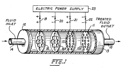
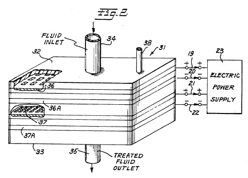
FIG. 2 is a schematic view of an
alternative form of system and apparatus according to the
invention.
BEST MODE OF PRACTICING THE
INVENTION
FIG. 1 is a partial schematic
drawing of a novel filtration and electrical treatment method
and system according to the invention. In FIG. 1 a plastic or
other closed, electrically insulating, treatment vessel 11 is
provided which has an elongated cylindrical shape with both
ends closed as shown at 12 and 13. The ends 12 and 13 are
provided with inlet and outlet openings through pipes 14 and
15, respectively. Secured within the hollow interior of
cylindrical vessel 11 are a series of filter plate elements
16, 16A, 17 and 17A. The filter plate elements preferably are
fabricated from an electrically conductive material such as
platinum which is substantially chemically inert and does not
chemically react with blood or other human body fluid or
synthetic fluids such as tissue culture medium. Each of the
filter plate elements 16 and 16A have a plurality of aperture
openings formed therein, which may or may not be axially
aligned with respect to each other, but are of a given size
for screening out and blocking particles contained in fluids
being filtered which are in excess of the given size. For
example, filter plate elements 16 and 16A may serve to filter
out particles having a cross sectional dimension which is
equal to or greater than 4 microns in size.
Downstream in the liquid flow path
through vessel 11, a second set of filter plate elements 17,
17A are supported. The filter plate elements 17, 17A likewise
are fabricated from a suitable electrically conductive
material such as platinum and have sets of aperture openings
formed therethrough which may or may not be axially aligned
with respect to each other. The aperture openings in the
filter plate elements 17 and 17A however are smaller and more
numerous than the openings in filter plates elements 16 and
16A. For example, the aperture openings in the filter plate
elements 17, 17A may be sized to block or filter out particles
having a size either equal to or in excess of 0.2 microns in
size up to 4 microns in size. While only two different size
sets of filter plate elements have been illustrated, it is
believed obvious to those skilled in the art that additional,
differently sized filter plate elements may be included within
the vessel 11 depending upon the nature of the particles which
one desires to filter out from fluid being treated with the
system. The filter plate elements 16, 16A and 17, 17A are
mounted within the interior of hollow, cylindrical vessel 11
substantially at right angles to the flow path that extends
longitudinally through vessel 11 from inlet end 12 to and
through outlet end 13. The mounting of the filter plate
elements is such that each filter element is electrically
insulated from the other filter plate elements mounted within
vessel 11.
In operation, fluid to be filtered
is supplied to the inlet end 12 of insulated vessel 11 via
inlet conduit 14 and traverses past the filter element plates
16, 16A, 17 and 17A then exits through the fluid outlet
conduit 15. At the exit side all particles entrained in the
fluid which are larger than 0.2 microns in size will have been
filtered out.
Concurrently with the
above-described filtering action, a low value electrical
potential of the order from about 0.2 to about 12 volts is
supplied to respective ones of the filter element plates 16,
16A, 17 and 17A from a direct current power source 23 via
selector switches 19, 20, 21 and 22. Switches 19, 20, 21 and
22 serve to electrically connect respective ones of the filter
plate elements to alternate polarity output electric
potentials supplied from the direct current electric power
supply 23. The electric potential supplied to respective ones
of the filter plate elements 16, 16A and 17, 17A may vary in
magnitude from about 0.2 to about 12 volts, for example, but
are of opposite polarity relative to adjacent filter plate
elements. For example, assume that a direct current electrical
excitation voltage having positive (+) polarity and a value of
4 volts is supplied to the filter plate element 16. Then a
negative (-) 4 volts or any other of the above-noted values is
supplied to the neighboring filter plate element 16A.
Consequently, there will be a potential difference of 8 volts
between the adjacent filter plate elements 16 and 16A through
which the fluid being treated must pass. If desired, the
potential difference existing between the next adjacent pairs
of plates 17, 17A may be adjusted either to higher or to lower
values in order to adjust the strength of the electric field
between the stages of filtration to a desired value.
In operation, the system functions
in the same manner as was described more fully in the
above-noted co-pending U.S. application Ser. No. 07/615,800
now issued U.S. Pat. No. 5,139,684, the disclosure of which
has been incorporated into the disclosure of this application
in its entirety. In effect, the electrical treatment
attenuates any virus, bacteria, fungus and/or parasite so as
to render them ineffective to infect normally healthy cells
while maintaining the biological usefulness of blood, and/or
other body fluids, and/or synthetic fluids being treated.
During operation, the low voltage electric potentials applied
to the respective filter plate elements should be of the order
from about 0.2 to about 12 volts and should produce current
flow through the fluid in current densities ranging from about
1 microampere per square millimeter of filter plate element
area exposed to fluid being treated to about 1 milliampere per
square millimeter with direct current excitation to about 2
milliamperes per square millimeter using alternating current
excitation. Treatment time within this range of parameters may
extend for a period of from about 1 minute to about 12 minutes
during electrification. However, treatment time may be longer
where, in certain cases, more complete attenuation of the
contaminants in the fluid being treated is desired. Also, in
certain circumstances where faster attenuation of contaminants
is desired, the excitation voltage may exceed the 0.2 to about
12 volt range indicated for most treatments.
During operation of the method and
system described with relation to the system described in the
above-noted U.S. patent application Ser. No. 07/615,800 now
issued U.S. Pat. No. 5,139,684, it has been observed that
under certain conditions bubbling of gas around one or more of
the plate elements such as 16, 16A, 17 or 17A can occur. To
avoid any adverse effects on the fluids being treated, it is
possible to reduce or even eliminate the production of bubbles
at the plate elements during operation by a number of
techniques. One is to fill the treatment vessel 11 so
completely that a gas phase cannot develop above the liquid in
the vessel.
Another technique that can be used
to avoid bubbling at the plates is to provide a suitable vent
pipe such as shown at 38 in the embodiment of the invention
shown in FIG. 2 of the drawings. By introducing pressurized
air or a suitable inert gas that does not chemically react
with the fluids being treated, the liquid can be pressurized
to the point that the liquid will not pass into the gas phase.
Another alternative is to vent any gas produced by bubbling to
the atmosphere via a vent tube such as 38 shown in FIG. 2.
Other techniques for obviating the bubbling around the filter
plate elements will be suggested to those skilled in the art.
During operation of the filter
elements 16, 16A, 17, 17A it is possible that one or more of
the filter elements can become clogged either partially or
otherwise. In this eventuality the system can be shut down and
the clogged element replaced with a new clean filter element.
Alternatively, it is possible to design the system so as to
provide two parallel treatment paths together with suitable
valve means to selectively supply fluid being treated to one
treatment path or the other. With such an arrangement it would
not be necessary to shut the system down during operation to
remove and replace a clogged filter plate element.
FIG. 2 is a partial perspective
view of a second embodiment of the invention which employs a
generally rectangular, box-like treatment vessel 31 fabricated
from plastic or other electrical insulating material closed by
an insulating top 32 and an insulating bottom 33. A fluid
inlet conduit 34 is provided in top 32 and an outlet conduit
35 is provided in bottom 33. The near sides and top of vessel
31 have been broken away to show the construction of the
mechanical filter elements 36, 36A and 37, 37A all of which
are fabricated from platinum or other relatively inert
electrically conductive material which is compatible with
human blood, and/or body fluids, and/or synthetic fluids,
and/or tissue. As shown in FIG. 2, the upper set of filter
plate elements 36 and 36A are relatively coarse compared to
the lower set of filter plate elements 37 and 37A. Again, for
example, the upper filter plate pair 36, 36A may be designed
to prevent particles which are 4 microns or larger in cross
section from passing through the elements while the lower set
of elements 37, 37A may be designed to prevent the passage of
particles 0.2 microns or larger from passing through. Again,
as a matter of design, the passages through the sets of filter
plates elements 36, 36A and 37, 37A may be axially aligned or
relatively displaced from each other so as to form a more
tortuous path for fluid flowing downwardly from the fluid
inlet 34 to the discharge outlet 35.
An electric power supply 23 is
provided which may be either direct current or alternating
current so long that measures are taken to assure that the
electric potential supplied to the respective filter plate
elements 36, 36A and 37, 37A are out of phase relative to each
other to assure that a potential difference exists between
adjacent pairs of the filter elements as described with
relation to FIG. 1.
In operation, the embodiment of the
invention shown in FIG. 2 functions in substantially the same
manner as that shown in FIG. 1 to provide for mechanical
filtering out of particles entrained in fluid to be treated by
the system which are greater than 0.2 microns in size.
Concurrently, electrification of the filter plate elements in
the manner described with relation to FIG. 1 causes
attenuation of virus, bacteria, fungus, and/or parasites which
might be entrained in the fluid being treated by the system
thereby rendering them ineffective as described more fully in
the above-referenced co-pending U.S. patent applications.
If necessary, anticoagulants may be
used in the fluids being treated with either embodiment of the
invention shown in FIG. 1 or FIG. 2.
INDUSTRIAL APPLICABILITY
The present invention provides a
combined filtration-electrical treatment method and system
which in operation serves to attenuate virus, bacteria, fungus
and/or parasites found in blood, body fluids and/or synthetic
fluids (such as tissue culture medium) used in the production
and purification of biologicals. The system is designed such
that no damage or impairment of the biological usefulness of
the fluids being treated occurs as a result of the combined
filtration and electrification treatments.
Having described two embodiments of
a novel combined filtration and electrification treatment
method and system according to the invention, other
modifications and variations of the invention will be
suggested to those skilled in the art in the light of the
above teachings. It is therefor to be understood that changes
may be made in the particular embodiments of the invention
described which are within the full intended scope of the
invention as defined by the appended claims.
---
US Patent # 5,188,738
Alternating Current Supplied Electrically
Conductive Method and System for Treatment of Blood
and/or Other Body Fluids and/or Synthetic Fluids with
Electric Forces
Abstract
A new alternating current process
and system for treatment of blood and/or other body fluids
and/or synthetic fluids from a donor to a recipient or storage
receptacle or in a recycling system using novel electrically
conductive treatment vessels for treating blood and/or other
body fluids and/or synthetic fluids with electric field forces
of appropriate electric field strength to provide electric
current flow through the blood or other body fluids at a
magnitude that is biologically compatible but is sufficient to
render the bacteria, virus, parasites and/or fungus
ineffective to infect or affect normally healthy cells while
maintaining the biological usefulness of the blood or other
fluids. For this purpose low voltage alternating current
electric potentials are applied to the treatment vessel which
are of the order of from about 0.2 to 12 volts and produce
current flow densities in the blood or other fluids of from
one microampere per square millimeter of electrode area
exposed to the fluid being treated to about two milliamperes
per square millimeter.
U.S. Class: 210/748 ; 204/164;
205/701; 210/243; 422/22; 422/44; 604/21; 604/6.0
References Cited
U.S. Patent Documents: 592735 ~ 672231 ~ 2490730 ~ 3692648 ~
3753886 ~ 3878564 ~ 3965008 ~
3994799 ~ 4473449 ~ 4616640 ~ 4770167 ~ 4932421 ~ 5049252 ~
5058065 ~ 5133932
Foreign Patent Documents: 995848
Other References
Proceedings of the Society for
Experimental Biology & Medicine, vol. 1, (1979), pp.
204-209, "Inactivation of Herpes Simples Virus with Methylene
Blue, Light and Electricity"--Mitchell R. Swartz et al. .
Journal of the Clinical
Investigation published by the American Society for Clinical
Investigations, Inc., vol. 65, Feb. 1980, pp.
432-438--"Mechanisms of Photodynamic Inactivation of Herpes
Simplex Viruses"--Lowell E. Schnipper et al. .
Journal of Clinical Microbiology,
vol. 17, No. 2, Feb. 1983, pp. 374-376, "Photodynamic
Inactivation of Pseudorabier Virus with Methylene Blue Dye,
Light and Electricity"--Janine A. Badyisk et al..
*Parent Case Text*
FIELD OF INVENTION
*Description*
This invention relates to novel
electrically conductive methods and systems employing
electrically conductive vessels provided with electrically
conductive surfaces for use in subjecting blood and/or other
body fluids and/or synthetic fluids such as tissue culture
medium to direct treatment by alternating current electric
forces.
BACKGROUND PROBLEM
It is now well known in the medical
profession and the general public that blood collected in a
blood bank from a large number of donors may be contaminated
by contaminants such as bacteria, virus, parasites and/or
fungus obtained from even a single donor. While screening of
donors has done much to alleviate this problem, the screening
of donors can and does miss occasional donors whose blood is
unfit for use. When this occurs and the unfit blood is mixed
with otherwise usable blood, the entire batch must be
discarded for transfusion purposes. Because of this problem,
the present invention has been devised to attenuate any
bacteria, virus (including the AIDS HIV virus) parasites
and/or fungus contained in blood contributed by a donor to the
point that any such contaminant is rendered ineffective for
infecting a normally healthy human cell, but does not make the
blood biologically unfit for use in humans. Similar problems
exist with respect to treatment of other body fluids, such as
amniotic fluids. The treatment method and system is also
applicable to mammals other than humans.
In addition to the above, there is
a need for methods and systems for the treatment of blood and
other body fluids both in in-situ processing wherein the
treated blood and/or other body fluids are withdrawn from the
body, treated and then returned to the body in a closed loop,
recirculating treatment process that is located near but
outside the patient's body, or the treatment can be effected
through implanted treatment system components.
In co-pending United States
application serial No. 07/615,800 entitled "Electrically
Conductive Methods and Systems for Treatment of Blood and
Other Body Fluids with Electric Forces"-Steven Kaali and Peter
M. Schwolsky, inventors, filed concurrently and co-pending
with this application, a similar treatment method and system
employing direct current excitation potentials is described
and claimed. The disclosure of co-pending application Ser. No.
07/615,800 hereby is incorporated into this application in its
entirety.
SUMMARY OF INVENTION
The present invention provides new
electrically conductive methods and systems using alternating
electric current excitation potentials for treating blood
and/or other body fluids, such as amniotic fluids, and/or
synthetic fluids such as tissue culture medium from a donor to
a transfusion recipient or to a storage receptacle, or for
recirculating a single donor's or patient's blood or other
body fluids. The treatment can be accomplished in a treatment
system external of the body or by implant devices for purging
contaminants using a novel electrically conductive vessel for
direct electric treatment of blood or other body fluids, such
as amniotic fluids, with alternating current electric field
forces of appropriate electric field strength to attenuate
such contaminants to the extent that bacteria, virus, fungus,
and/or parasites contained in the blood or other body fluids
are rendered ineffective to infect and/or affect normally
healthy human cells. The treatment, however, does not render
the blood or other body fluids biologically unfit for use in
humans or other mammals after the treatment. The new methods
and systems according to the invention achieve these ends
without requiring time consuming and expensive processing
procedures and equipment in addition to those normally
required in the handling of blood or other body fluids or
synthetic fluids. The invention can be used to achieve the
electric field force treatment during the normally occurring
transfer processing from a donor to a recipient or to a
collection receptacle, or recirculation of a single donor's or
patient's blood or other body fluids, such as amniotic fluids.
BRIEF DESCRIPTION OF DRAWINGS
The above and many other objects,
features and attendant advantages of this invention will be
appreciated more readily as the invention becomes better
understood from a reading of the following detailed
description, when considered in connection with the
accompanying drawings, wherein like parts in each of the
several figures are identified by the same reference
characters, and wherein:
FIG. 1 is a diagrammatic,
fragmentary, elevational view of a new blood transfer system
using a novel alternating current electrically conductive
treatment vessel in the form of conductive tubing to directly
treat blood being transferred to a storage receptacle with
electric field forces according to the invention;
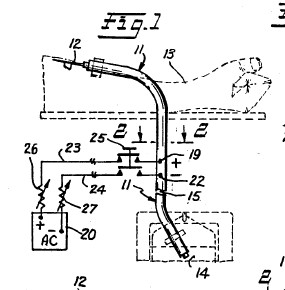
FIG. 2 is an enlarged, horizontal
cross sectional view of the novel electrically conductive
tubing treatment vessel taken across lines 2--2 of FIG. 1;
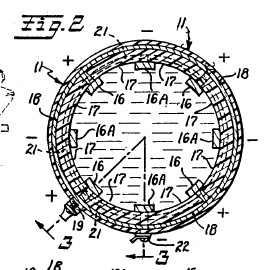
FIG. 3 is a longitudinal, vertical
sectional view of the novel electrically conductive tubing
treatment vessel taken along the staggered section lines 3--3
of FIG. 2;
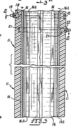
FIG. 4 is a view similar to FIG. 2
showing a different construction of the novel electrically
conductive tubing treatment vessel;
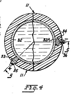
FIG. 5 is a view similar to FIG. 3,
taken along the staggered section lines 5--5 of FIG. 4;
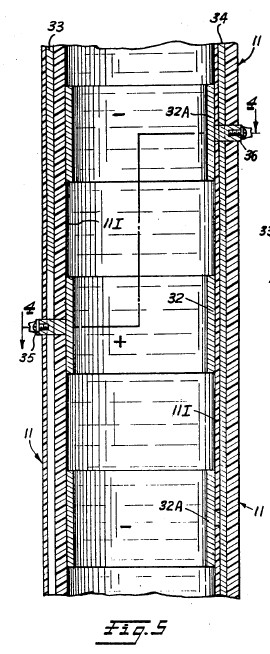
FIG. 6 is a diagrammatic,
fragmentary, elevational view showing a different modification
of a novel blood transfer system using a novel electrically
conductive tubing treatment vessel, and which employs a blood
pump and a blood flow regulator;
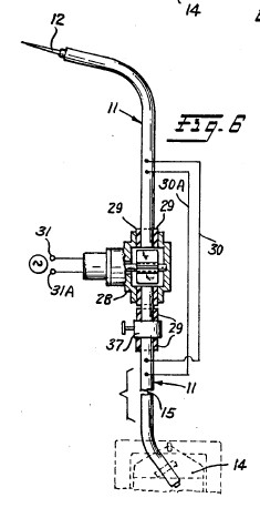
FIG. 7 is an enlarged cross
sectional view, similar to FIG. 2 that shows an electrically
conductive tubing treatment vessel fabricated from
longitudinally extending, integrally molded strips of
alternate polarity, conductive polymer interconnected by
integrally molded, insulating, longitudinally extending strips
made of polymer or other insulating material;
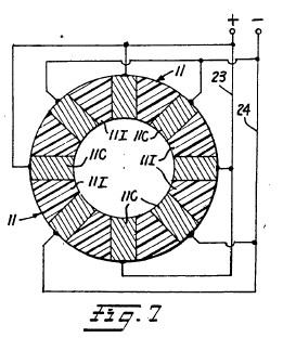
FIG. 8 is a diagrammatic,
fragmentary elevational view showing a different form of a
blood transfer system according to the invention wherein a
small electrically conductive vessel in the form of a short
piece of tubing and a miniaturized battery power source are
implanted in the arm of a human being to provide a novel
electrically conductive blood and other body fluid treatment
system which operates in a closed loop, recirculating manner;
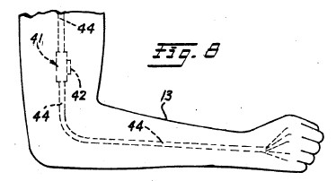
FIG. 9 is a partial, diagrammatic
sectional view of the upper arm portion of a human being and
shows in greater detail the construction of a specially
designed miniaturized, electrically conductive treatment
vessel with associated miniaturized battery electric power
source and DC to AC power converter for use in the implant
treatment system shown in FIG. 8;
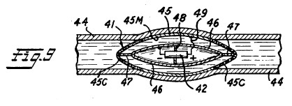
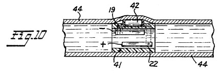
FIG. 10 illustrates the details of
construction of a somewhat different form of miniaturized
electrified treatment tubing for use in an implanted treatment
system of the type shown in FIG. 8 and built according to the
invention;
FIGS. 11 and 11A illustrate still a
different construction for the electrified treatment tubing
for use in practicing the invention wherein the tubing has a
square or rectangular cross section with upper and lower
conductive sides and intervening right and left sides
separating the two conductive sides made from plastic or other
suitable electrical insulating material;
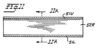
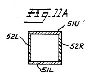
FIG. 12 is a perspective top and
side view of a novel electrified, closed, octagonally-shaped,
flat, box-like treatment vessel having an enlarged cross
sectional area relative to the cross sectional diameter of the
inlet and outlet tubes supplying the interior of the treatment
vessel;
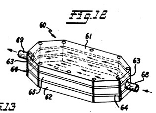
FIG. 12A is a partial, cross
sectional view of the enlarged treatment vessel shown in FIG.
12;
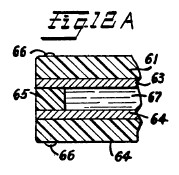
FIG. 13 is a perspective view of a
second form of enlarged cross sectional area treatment vessel
having an exterior shape similar to that of FIG. 12, but
wherein the electrically conductive electrodes of the
treatment vessel comprise interleaved conductive plates with
one set of alternate ones of the plates being electrically
insulated from the remaining set, and wherein different
polarity electric potentials are applied to the respective
sets. If desired, the electrode plates may be formed from an
electrically conductive porous material;
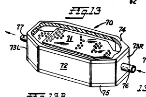
FIG. 13A is a partial, cross
sectional view taken through the electrically conductive
treatment vessel shown in FIG. 13;

FIG. 13B is a sectional view taken
through staggered line 13B--13B of FIG. 13A;
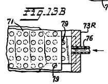
FIG. 14 is a longitudinal sectional
view of still a different form of enlarged diameter
electrified treatment vessel wherein the vessel is in the form
of an elongated cylinder, and the sets of conductive
electrodes mounted therein are concentrically arrayed within
the interior of the treatment vessel and maintained at
different electric potentials;
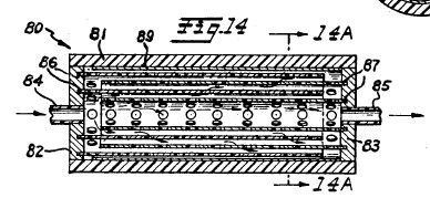
FIG. 14A is a cross sectional view
of FIG. 14 taken through plane A--A;
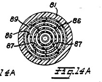
FIG. 15 is an enlarged longitudinal
sectional view of still another form of an enlarged cross
sectional area treatment vessel according to the invention
wherein the electrically conductive electrodes of the
treatment vessel are comprised by longitudinally extending
needle-like electrodes with alternate ones of the needle-like
electrodes being provided with opposite polarity electric
potentials;
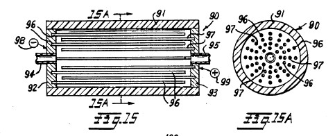
FIG. 15A is a cross sectional view
of the treatment vessel shown in FIG. 15 taken through plane
A--A of FIG. 15;
FIG. 16 is a perspective view of
still another form of enlarged cross sectional area treatment
vessel according to the invention wherein the treatment vessel
comprises a relatively large block of insulating material
having parallel, longitudinally extending, open ended tubes
formed through its length. The tubes are provided with
electrically separated, opposed, parallel extending conductive
plate electrodes which have opposite polarity electric
potentials applied thereto. The ends of the tubes open into
and are supplied from, or supply, respective reservoirs formed
on the respective ends of the central block of insulating
material containing the tubes, with inlet and outlet conduits
for body fluids to be treated connected to the free ends of
the respective reservoirs;
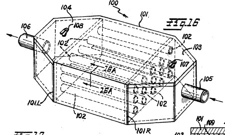
FIG. 16A is a partial
cross-sectional view taken through 16A--16A of FIG. 16;
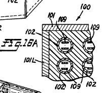
FIG. 17 is a perspective view of an
enlarged cross sectional area treatment vessel similar to FIG.
16 wherein the body of the treatment vessel is cylindrical in
nature;
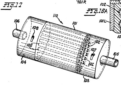
FIG. 18 is a diagrammatic,
fragmentary elevational view of a human blood or other body
fluid treatment system according to the invention employing
one of the larger cross sectional dimension fluid treatment
vessels shown in any one of FIGS. 12-16 of the drawings, and
which is suitable for use in a continuous flow through
recirculating body fluid treatment system; and
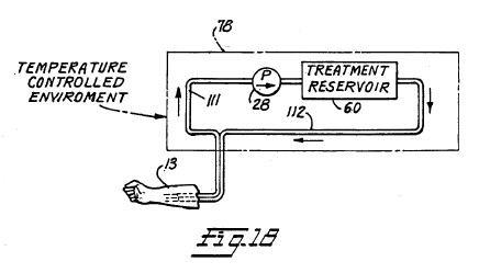
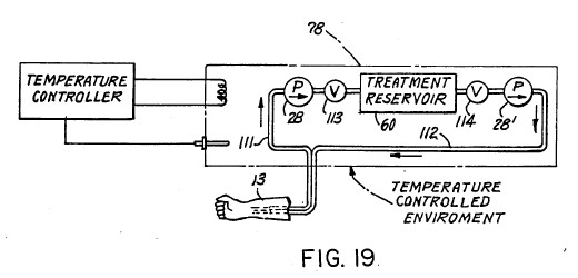
FIG. 19 is a diagrammatic,
fragmentary elevational view of still another human blood or
other body fluid, closed loop, recirculating treatment system
according to the invention designed for use with the enlarged
diameter fluid treatment vessels illustrated in FIGS. 12-16,
and which employs both inlet and outlet fluid pumps on each
side of the treatment vessel. With this arrangement the system
can be operated in an intermittent manner to allow batch
treatment of the body fluids to fully take place before
passage of the body fluids being treated back to the patient.
BEST MODE OF PRACTICING INVENTION
FIG. 1 is a schematic illustration
of one form of a novel blood and other body fluid treatment
system according to the invention. FIG. 1 shows an
electrically conductive blood and/or other body fluid
treatment vessel constructed according to the invention which
is in the form of intravenous tubing 11 interconnected between
a hypodermic needle 12 and a blood storage receptacle 14. The
needle 12 is inserted in an artery or vein of the arm 13 of a
blood donor and the tubing 11 leads from the arm 13 to the
receptacle 14. Alternatively, the system could be set up to
transfer blood from the storage receptacle 14 to the arm of a
recipient or could be designed to recirculate the blood
through electrified tubing 11 back to the donor. The
electrically conductive tubing 11 may be of any desired length
as indicated by the break at 15 so that it can be
appropriately set up to lead from a comfortable position for
the donor from whose arm 13 the blood is being taken to a
proper storage location for the receptacle 14. The greater the
length of the electrified portion of tubing 11, then the more
extended is the exposure of the blood (or other body fluid) to
the electric field force effects and low level, biologically
compatible current flow through the body fluid being treated
thereby assuring adequate electrification treatment of the
fluid without impairing the biological usefulness of the blood
or other body fluid being treated.
FIG. 2 is a cross sectional view of
the electrically conductive tubing 11 taken through plane 2--2
of FIG. 1. The tubing 11 may be from 1 to about 20 millimeters
in inside diameter, although it may be larger or smaller in
diameter depending upon the intended application. For example,
if the blood transfer system is for the purpose shown in FIG.
6, then the tubing may have a cross sectional dimension of
about 5 millimeters. However, if the intended use is in an
implanted blood treatment system, such as shown in FIG. 8,
then the tubing diameter must be designed to result in a
flow-through rate corresponding to the natural circulatory
blood flow rate of the patient in which the system is
implanted, and must be long enough to assure effective
electrification treatment at the flow rate selected. The
tubing 11 is formed from plastic, rubber, medical grade
polymer, or other suitable material which is compatible with
human fluids and/or tissue. A plurality of physically
separated, electrically conductive surface segments form
opposed, parallel electrodes shown at 16 and 16A on the inside
of tubing 11 from electrically conductive materials such as
platinum, platinum alloys, silver, silver or platinum covered
alloys, or other similar conductive materials such as
conductive polymers, or silver or platinum covered polymers
which are compatible with human fluids and tissue. The spacing
between opposed electrodes 16 and 16A is of the order of 1 to
19 millimeters and perhaps may be more or less dependent upon
the application and the conductivity of the body fluids being
treated.
FIG. 3 is a longitudinally
extending sectional view along the axis of tubing 11 taken
through staggered section lines 3--3 of FIG. 2. From FIG. 3 of
the drawings it will be seen that the electrically conductive
surface segments 16 and 16A all comprise longitudinally
extending, zebra-like stripe or strip electrodes which extend
longitudinally in parallel with the longitudinal axis of the
tubing 11. In between each longitudinally extending conductive
stripe electrode 16 or 16A is a longitudinally extending
electric insulating area 17 which electrically isolates the
alternate electrically conductive, zebra-like stripe
electrodes 16 and 16A one from the other.
As best shown in FIG. 3, a first
set of alternate electrically conductive surface stripes 16
are electrically connected in common to a first annular
terminal buss 18 which circumferentially surrounds the tubing
11 and is embedded within the sidewalls of the tubing 11 at a
suitable point along its length. The design is such that the
first annular terminal buss 18 is electrically isolated from
the remaining second set of alternate, electrically conductive
surface stripe electrodes 16A and is electrically connected
through a conductor terminal 19 to an alternating current
source of electric excitation potential. AC source 20 may
comprise the output from an AC to AC voltage converter for
converting 110 volt AC potential to the desired 0.2 volts to
12 volts for use in the invention. For those treatment systems
which are to be implanted as described hereafter, the AC
source may comprise a miniaturized DC to AC converter for
converting the DC voltage from a miniaturized battery to low
voltage (0.2 to 12 volts) AC. As best depicted in FIG. 2, all
of the first set of positive electrically conductive stripes
16 are physically and electrically connected in common to the
first annular terminal buss 18 so that all of the conductive
stripes 16 are maintained at a constant, alternating current
electric excitation potential.
A second annular terminal buss 21,
which circumferentially surrounds the tubing 11, is embedded
within the tubing 11 at a point along its length displaced
from the position of the first annular terminal buss 18 and is
spaced inwardly towards the inside diameter of the tubing
relative to the first annular buss 18. By this arrangement it
is possible to electrically connect the remaining second set
of alternate electrically conductive surface stripes 16A in
common to the second annular terminal buss 21 in a manner such
that the second annular terminal buss is electrically isolated
from the first annular terminal buss 18 as well as the first
set of alternate electrically conductive surface stripes 16.
As shown in FIG. 3, the second annular terminal buss 21 is
provided with an outside terminal conductor connection 22 for
connecting the annular buss 21 and annular buss 18 across AC
source 20 as shown in the system drawing of FIG. 1. The second
set of alternate electrically conductive surface stripes 16A
are all provided with internal connector studs which
physically and electrically connect all of the 16A stripes in
common to the second annular terminal buss 21 so that all of
these conductive stripes will be maintained at a potential
opposite to that from the potential applied to the first set
of electrically conductive stripes 16 by annular buss 18.
As described earlier, the AC source
of electric potential 20 may constitute an AC to AC converter
for converting 110 volt AC to 0.2 to 12 volt AC or a DC to AC
converter for converting 12 volt DC to 0.2 to 12 volt AC. The
AC source 20 is connected to the conductor terminals 19 and 22
through electric supply conductors 23 and 24 preferably by a
double pole, double throw, on-off control switch 25. In
preferred embodiments of the invention, voltage controlling
variable resistors 26 and 27 also are included in the electric
supply conductors 23 and 24 in order to control the value of
the excitation voltage developed between the alternate sets of
conductive surface stripes 16, 16A.
In operation, the donor whose blood
is to be taken, or the recipient who is to be given blood, or
is to have his or her blood recycled, is made comfortable on a
cot with his or her arm 13 extended and the interconnecting
electrically conductive tubing 11 having the hypodermic needle
12 for withdrawal, or supplying, or recycling of blood set up
as shown in FIG. 1. When both the donor/recipient and the
system is in readiness, the control switch 25 is closed so
that an electric field is built up across the oppositely
disposed electrically conductive zebra-like stripes 16, 16A,
etc. Voltages of the order of from 0.2 to 12 volts are applied
to the conductive surfaces 16, 16A For this purpose it is
important to note that the hypodermic needle should be
electrically isolated via conventional electrically insulating
IV tubing from any of the zebra stripe electrodes 16, 16A so
that the donor/recipient does not receive a shock. By this
precaution, he or she will not even be aware of the existence
of the electric field within the electrically conductive
tubing 11. With the treatment system thus conditioned, the
hypodermic needle is inserted into a vein in the
donor's/recipient's arm and blood is withdrawn, given, or
recycled through the tubing 11.
As the blood passes through the
electric fields produced within the electric conductive tubing
11 it will be subjected to and treated by biologically
compatible electric current flow through the blood or other
body fluid with a current density of from one microampere per
square millimeter (1 .mu.A/mm.sup.2) of electrode cross
sectional area exposed to the fluid to about two milliamperes
per square millimeter (2 mA/mm.sup.2) dependent upon field
strength of the electric field gradient existing between
electrodes 16 and 16A, the space between the electrodes 16,
16A and the conductivity (resistivity) of the body fluid being
treated. Recent experiments have proven that exposure to
electric fields induced by supply voltages in the range
produces electric current flow through blood of the order of 1
to 100 microamperes. Effectiveness is dependent upon length of
time of treatment in conjunction with the magnitude of the
biologically compatible current flow. For example, treatment
of virus in media at 100 microamperes for 3 minutes has been
observed to substantially attenuate (render ineffective) the
AIDS virus. Similar treatment at other field strength values
and lengths of time will have a similar attenuating effect on
bacteria, virus, parasites and/or fungus which are present in
blood or other body fluids being treated. By controlling the
length of time and field strength values that blood is
subjected to the electric field forces, undesirable
contaminants such as virus, bacteria, fungus and/or parasites
will be adequately attenuated to the point that they are
rendered ineffective by the sustained action of the electric
current flow as the blood travels from the hypodermic needle
12 to the storage bag 14, or vice versa, or in a recycling
mode. The length of travel of the blood through the sustained
electric field induced current flow also can be adjusted so
that the blood is subjected to the electric field force for
time periods of the order of from one to six minutes at least.
At the current values noted above this is believed adequate to
attenuate (render ineffective) bacteria, virus (including the
AIDS virus), parasites and/or fungus entrained in blood or
other body fluids, but does not render the fluids unfit for
human use or impair their biological usefulness.
The species of the invention shown
in FIGS. 2 and 3 is advantageous since it is possible to
fabricate the treatment tubing by preforming the conductive
segments 16 and 16A on the tubing walls while it is in a flat
planar condition, and then rolling the walls into tubular form
using a suitable mandrel. The adjoining longitudinal edges of
the planar member after rolling are thereafter heat sealed
along a longitudinally extending seam located within one of
the electrically insulating sections 17. Particular attention
must be paid to the juncture of the ends of the annular
terminal busses 18 and 21 during the rolling and heat sealing
steps to assure that good electrical interconnection and
continuity at these junctures of the annular terminal busses
is provided in the completed treatment tubing. The conductive
electrode segments 16, 16A may be electro-deposited,
chemically formed, separately formed conductive polymer
surfaces, or conductive foil or wires adhesively secured to
the side walls of the tubing 11 in advance of the rolling and
sealing using techniques well known in the printed circuit and
integrated circuit manufacturing technologies.
FIG. 6 is a diagrammatic,
fragmentary, elevational view of a modified blood treatment
system using the novel electrically conductive treatment
tubing in accordance with the invention. In the FIG. 6
embodiment of the invention, a blood pump 28 of conventional,
commercially available construction is inserted in the tubing
11 at some point along its length. The blood pump 28 is
electrically isolated from the zebra striped conductive
surfaces 16, 16A by suitable insulators 29 formed on the blood
input-output connections of pump 28. Provision for
electrically bypassing the blood pump 28 (if need be) is made
through the shunt conductors 30, 30A which maintain electrical
continuity of the alternating current excitation potential
applied to the conductive stripes 16, 16A on each side of pump
28. For convenience, the alternating current excitation source
20 and its connection to the electrically conductive tubing 11
has not been shown in FIG. 6 but would have to be provided. A
separate source of excitation current for running the blood
pump 28 is provided from a conventional 110 volt alternating
current source through the input terminals 31, 31A.
In systems employing a blood pump,
it may be desirable in some applications to provide a blood
flow regulating valve 37 inserted in the system at the output
of blood pump 28 and within the by-pass loop 30, 30A for the
conductive stripes 16, 16A. By thus controlling blood flow,
the electrified transfer system safely can be employed in a
closed loop recycling system for withdrawing blood from a
patient, electrically treating the blood as described above
and then returning the electrically treated blood to the
patient. This procedure is referred to herein as recycling.
The system of FIG. 6 also can be used in those situations
where the blood flow of a donor's blood is not sufficient to
assure supply of an adequate amount of blood to or from the
collection receptacle 14 or other recipient. It may also be
desirable to have a blood flow regulating valve such as 37 in
non-pump systems.
FIGS. 4 and 5 of the drawings show
another embodiment of the invention wherein the electrically
conductive treatment tubing 11 includes electrically
conductive electrode segments 32 and 32A which are in the form
of zebra stripes that extend radially around the inside
diameter of tubing 11 in spaced-apart, alternating polarity,
conductive annular bands 32 and 32A separated by insulating
surface bands 11I which serve to electrically isolate the
respective first set of conductive zebra stripes 32 from the
second set of conductive zebra stripes 32A. The first set of
alternate ones of the electrically conductive annular stripes
32 are electrically connected in common to a first
longitudinally extending terminal buss bar 33 that is embedded
within tubing 11 in parallel with the longitudinal axis of the
tubing and electrically isolated from the remaining second set
of alternate electrically conductive annular stripes 32A. The
first longitudinally extending terminal buss bar 33 is
designed for connection to one output terminal of a source,
such as 20, of alternating current electric excitation
potential through a supply conductor connection 35 on the
exterior surface of the tubing 11.
A second longitudinally extending
terminal buss bar 34 is embedded within the body of tubing 11
and is electrically connected to the remaining second set of
alternate electrically conductive annular stripes 32A. The
second longitudinally extending terminal buss bar 34 is
electrically isolated from the first longitudinally extending
terminal buss 33 and the first set of alternate electrically
annular stripes 32. Terminal buss bar 33 is designed for
connection to a second output terminal for the alternating
current source of electric excitation potential. For this
purpose an input supply conductor connection 36 is directly
connected through the exterior surface of tubing 11 and to the
second longitudinally treatment extending terminal buss bar
34.
In operation, the embodiment of the
invention shown in FIGS. 4 and 5 is physically arranged in a
blood treatment system in the manner illustrated in FIG. 1 of
the drawings with the positive polarity and negative polarity
zebra annular stripes being connected to the respective output
terminals of AC source 20 via control switch 25. If required,
a blood pump such as 28 and blood flow regulating valve 37
shown in FIG. 6 can be included in the blood transfer system
employing electrified tubing as shown in FIGS. 4 and 5.
Similar to the system shown in FIG.
1, a blood transfer system employing the embodiment of the
invention shown in FIGS. 4 and 5 would be electrically excited
in advance of injection of the hypodermic needle 12 into the
arm of a blood donor so that all blood passing through the
tubing 11 will be subjected to electric forces produced
between the alternate polarity annularly formed conductive
bands 32 and 32A. Experience with the invention will establish
what length is required for the electrification field.
However, for initial installations the length of the
electrified field as related to the flow of blood through
electrified tubing 11 should correspond to at least the 1-6
minute treatment time mentioned earlier. This is achieved by
using an extended array of the alternate annular zebra bands
32 and 32A of adequate length to assure thorough subjection of
blood to electric current flow produced between the
alternating polarity zebra stripes 32 and 32A. The electric
field force intensity applied to the blood by means of the
electrified tubing is anticipated to be of the order of from
0.2 to 12 volts similar to the embodiment of the invention
shown in FIGS. 1-3.
In place of supplying continuous
alternating current excitation to the conductive stripes 16,
16A of FIGS. 2 and 3 or 32, 32A of FIGS. 4 and 5, it also is
possible to excite these electrically conductive segments of
tubing 11 with pulsed waveform direct current excitation
potentials. For use in this manner, the pulse rate of the
pulsed waveform excitation potentials must be sufficiently
high to maintain continuous current flow through blood being
treated. In addition, it may be desirable to couple a bank of
storage capacitors in parallel across respective pairs of
opposite polarity electrically conductive segments 16, 16A and
32, 32A where operation in a pulsed DC mode is desired.
FIG. 7 of the drawings is a cross
sectional view of another embodiment of the invention which is
substantially different from those previously described. In
FIG. 7, the material used for fabrication of the tubing 11 is
one of the new space-age polymer materials which can be either
highly electrically conductive, insulating, or semiconducting
and may have values of conductivity ranging from essentially
fully conductive to insulating. In the embodiment of the
invention of FIG. 7, the conductive surface areas on the
inside diameter of the tubing 11 are actually formed into
segments, such as 11C, of the cross sectional area of the
tubing 11 fabricated from the highly conductive polymer
material. The intervening segments of the tubing 11I which
separate the conductive segments 11C are integrally formed
from the highly insulating polymer material. Suitable positive
polarity and negative polarity potentials are applied to the
exterior surface areas of alternate ones of the sets of
conductive polymer segments 11C from a source of electric
potential via the conductors 23 and 24 as illustrated
schematically in FIG. 7.
It will be appreciated that the
embodiment of the invention shown in FIG. 7 is much simpler
and hence less expensive to make in that it requires fewer
processing steps than the embodiments of the invention shown
in FIGS. 1-6. In other respects, the embodiment of the
invention shown in FIG. 7 would be used in a blood transfer
system similar to that shown in FIG. 1 or 6 with or without a
blood pump 28 and blood flow regulating valve 37 to effect
transfer of blood from a donor to a receptacle or recipient in
the event of a transfusion or recycling. During the blood
transfer process, again it would be necessary to provide
alternating current excitation potentials across the
spaced-apart, alternate sets of electrically conductive
polymer segments 11C prior to passing blood through the tubing
11. This will assure that all of the blood being transferred
is subjected to the electric field forces produced between the
alternate conductive surfaces 11C. As a variation of the FIG.
7 embodiment, which visualizes that the segments 11C and 11I
all extend longitudinally and parallel to the longitudinal
axis of tubing 11, it would be possible, but more elaborate to
design, to employ alternate radially surrounding annular
conductive segments 11C and interlacing insulating segments
11I similar to FIG. 5, but such fabrication would require
somewhat more complex terminal buss bar electric supply
connections 23 and 24 than those shown in FIG. 7.
FIG. 8 is a fragmentary,
diagrammatic, elevational view showing a form of blood
treatment system according to the invention wherein a small
electrically conductive vessel 41 in the form of a short piece
of electrified tubing and a combined miniaturized DC to AC
converter and battery power source 42 are implanted in the arm
of a human being. The electrified tubing 41 may be in the form
of any of the prior disclosed electrified tubing structures
described with relation to FIGS. 1-7, but which are fabricated
in miniaturized form so that the tubing 41 and power package
42 can be inserted in a section of or surrounding a vein 44 of
the arm 13 of a patient whose blood is being treated. The
implantation is such that the blood through the patient's vein
44 naturally is pumped through the short piece of electrified
tubing 41 while circulating blood to the hand of the patient
to thereby form a closed loop, recirculating, implanted
treatment system that comprises an integral part of the
circulatory system of the patient being treated. Because the
parameters of such an implanted system are necessarily small,
a single passage through the implanted electrified tube 14 may
accomplish relatively little attenuation of contaminants in
the blood. Therefore, it is the repeated passage of small
portions of the patient's blood continuously twenty-four hours
a day and for as many days as are needed which will gradually
attenuate the contaminants to the point where they are
rendered ineffective as described earlier.
FIG. 9 is a partial, fragmentary,
sectional view of the upper arm portion 13 of a vein or artery
of a patient in which a treatment system according to the
invention has been implanted, and shows in greater detail the
construction of a specialized, miniaturized, electrically
conductive treatment vessel with associated miniaturized
battery electric power source and DC to AC converter for use
in an implanted treatment system as shown in FIG. 8. In FIG.
9, the electrified vessel 41 is in the form of an outer
housing 45 that is in the shape of a football which is
implanted within the interior walls 44 of an artery or a vein.
The outer housing 45 is comprised by a central,
cylindrically-shaped portion 45M of solid conductor such as
platinum which is biocompatible with human blood and tissue
and has integrally formed, conically-shaped porous ends 45C
which are attached to and form an electrically conductive
screen grid (at the same potential) as the mid portion 45M.
The conical end portions 45C both are perforated and may be in
the nature of a screen or mesh wire and of the same material
composition as the mid portion 45M. Disposed within the outer
housing 45 is a inner housing 46 which is tear-drop shaped and
secured within the central portion 45M of the outer housing by
suitable insulating support spider legs 47. The inner housing
46 likewise is formed from platinum or other suitable
biocompatible conductive material and has supported within its
interior a miniaturized AC source comprising a miniaturized
battery and AC to DC converter 42 secured to the conductive
walls of inner housing 46 by conductive support legs 48. The
support legs 48 serve as terminal connectors from one terminal
of AC power converter 42 to the inner housing 46 so that it is
maintained at one polarity excitation potential. The remaining
opposite polarity terminal of miniaturized AC source 42 is
connected through an insulated conductor 49 to the central
portion 45M of outer housing 45 whereby the entire outer
housing including the meshed conical end portions 45C are
maintained at an opposite polarity potential from the inner
housing 46.
Prior to implantation in a patient,
the electrified vessel shown in FIG. 9 is activated by
connection to AC source 42 so that an electric field gradient
is produced across the space between the inner and outer
housings 45 and 46. Following implantation of the activated,
electrified treatment vessel 41, its presence in a vein or
artery will cause all blood flowing through the vein or artery
to pass between the side walls of the inner and outer housings
45 and 46 so as to be subjected to the electric field force
gradient existing in these spaces. The presence of the
electric field forces will induce a current flow through the
blood passing between the interior and outer housings as
explained above which will result in attenuating bacteria,
virus, parasites and/or fungus which are present in the blood
as contaminants. Here again, because of the relatively small
portion of the total blood flowing in a patient that will be
treated by the device within a given time period, it is the
repeated, recycling process treatment of the blood over a
prolonged period of time that will result in attenuation of
the contaminants in the blood to the point where such
contaminants are rendered ineffective as described earlier.
In order to further assure adequate
treatment of the blood of a patient receiving the implant
device, it is recommended that the blood be treated in an
external treatment processing facility such as described
earlier in FIGS. 1 and 6 or to be described hereinafter with
relation to FIGS. 18 and 19 in which the total capacity of the
treatment system is greater whereby substantial attenuation
effect can be achieved in a comparatively shorter time period
yet to be determined, and then the in vitro implant treatment
system such as shown in FIGS. 8, 9 and 10 can be used to
maintain the attenuated condition and to prevent any
subsequent build up of contaminants after the initial
treatment, if determined to be desirable.
FIG. 10 is a fragmentary,
diagrammatic view of a partial vein or artery 44 showing in
greater detail the cylindrical or tubular electrified
treatment vessel 41 originally described with relation to FIG.
8. This implant treatment vessel 41 is miniaturized so that it
is in effect an open-ended cylinder in shape and has a
diameter comparable to that of a large vein or artery and so
that it can be grafted or implanted into the vein or artery as
illustrated in FIG. 10. The tubular treatment vessel 41 may be
designed pursuant to FIGS. 2 and 3 of the drawings, for
example. For this application, the battery source of power and
interconnected DC to AC converter 42 are annular in shape and
are slipped over the tubular treatment vessel 41 in the manner
shown. In FIG. 10 a longitudinal sectional view of the hollow
annular-shaped treatment vessel 41 and AC power source 42 is
illustrated. At the point where the battery driven AC power
source 42 fits over the tubular treatment vessel 41, the
respective terminals of the AC power source 42 are exposed to
engage the corresponding positive and negative supply
terminals 19 and 22 of the tube 41 so that the resulting
structure has a minimum exterior profile to facilitate
implantation. From a comparison of FIG. 10 to FIG. 9 of the
drawings, it will be appreciated that the FIG. 9 treatment
vessel introduces some flow restriction in the vein or artery
in which it is implanted and for this reason the construction
shown in FIG. 10 is preferred.
FIGS. 11 and 11A of the drawings
illustrate a construction for the electrified treatment vessel
51 wherein the treatment vessel is in the form of square or
rectangular cross sectionally-shaped open-ended tubing. The
treatment tubing 51 provided with a square or rectangular
shape so that provision of opposed, parallel conductive
electrode surfaces 51U and 51L is greatly simplified as best
seen in FIG. 11A of the drawings, which is a cross sectional
view taken through plane 11A--11A of FIG. 11. By fabricating
the upper and lower surfaces of the tubing 11 from
electrically conductive material such as platinum, etc., and
separating the upper and lower surfaces 51U and 51L by
electrically insulating side walls 52R and 52L, provision of
the electrically isolated, opposed, parallel electrode
surfaces is simplified and the resulting treatment vessel
introduces minimum restriction to flow of blood. By connecting
the upper surface 51U to one terminal of the AC power source
42 and connecting the lower surface 51L to the opposite
terminal, AC electrification of the interior area of the
tubing wherein the fluids to be treated flow is readily
achieved with a greatly simplified electrode structure.
Variations of this structural feature wherein the side
insulating surfaces 52R and 52L are curved with their concave
surfaces facing each other and the cross sectional area of the
upper and lower conductive surfaces 51U and 51L tailored to
provide a desired current density, tubular treatment vessels
such as shown in FIGS. 11 and 11A could be readily provided
for use in implantation devices such as that illustrated in
FIG. 8.
FIG. 12 is a perspective view of a
novel, electrified, closed, octagonally-shaped, flat, box-like
treatment vessel 60 according to the invention which provides
an enlarged cross-sectional area relative to the cross
sectional diameter of the inlet and outlet tubing supplying
the interior of the treatment vessel whereby increased
through-put of a fluid being treated can be achieved in a
given time period. The treatment vessel 60 shown in FIG. 12 is
comprised essentially of upper and lower, octagonally-shaped,
flat insulating plates 61 and 62, respectively, of an
insulating material which is compatible with human blood
and/or other body fluids. Disposed immediately below and above
the upper and lower plates 61 and 62 are octagonally-shaped,
conductive electrode members 63 and 64, respectively, which
are separated and electrically isolated one from the other by
a surrounding electric insulating gasket member 65. The entire
structure is sandwiched together and held in assembled
relation by threaded thru-pins 66 as best seen in FIG. 12A of
the drawings. The insulating gasket 65 which may be of teflon
defines an open space 67 between the two conductive electrode
members 63 and 64 into which the blood or other body fluid to
be treated is introduced via inlet and outlet conduits 68 and
69. Alternating current electric potentials are applied across
the respective conductive plates 63 and 64 to produce an
electric field force across the intermediate space 67 through
which the fluids being treated flow between electrode plates
63 and 64. By thus structuring the treatment vessel, increased
treatment surface area is provided to the blood or other body
fluid flowing through the space 67 whereby in a given time
period an increased quantity of fluids can be treated.
FIG. 13 is a perspective view of
another form of enlarged cross sectional area treatment vessel
70 having an exterior shape similar to that of the treatment
vessel shown in FIG. 12. The electrified treatment vessel
shown in FIG. 13 differs from that in FIG. 12, however, in the
construction of its electrically conductive electrodes which
comprise a plurality of interleaved, conductive, flat,
electrode plates 71 and 71A. The electrode plates 71 are
secured in and project inwardly from a right hand (RH)
conductive end plate 73R as shown in FIG. 13A. The alternate
set of flat electrode plates 71A are secured to and project
inwardly from a corresponding conductive end plate 73L on the
left hand end of the treatment vessel 70. The conductive end
plates 73R and 73L and coacting insulating side plates 72
which insulate the conducting end plates from one another,
form an octagonally-shaped box frame which is closed by upper
and lower insulating top and bottom insulating plates 74 and
75. The conductive end plates 73R and 73L have a central
opening formed therein into which inlet and outlet tubes 76
and 77 are secured as best seen in FIG. 13 for providing inlet
and outlet flow through connection to the treatment vessel 70.
The alternate sets of flat
electrode plates 71 and 71A extend parallel to one another and
are provided with alternating current electric potentials
supplied across the respective sets of interleaved electrode
plates via the respective conductive end members 73R and 73L.
If desired, the respective flat conductive electrode plates 71
and 71A may be fabricated from a perforated material as shown
in FIG. 13B of the drawings. Also, it may be desirable that
some form of thermal insulation, or a thermally controlled
chamber be provided around the exterior of the treatment
vessel 70 as indicated by the thermal insulation 78 shown in
FIG. 13A.
In operation, electrified treatment
vessel 70 shown in FIGS. 13, 13A and 13B functions in
essentially the same manner as was described earlier with
respect to FIGS. 1-7 to effect attenuation of contaminants
such as bacteria, virus and fungus contained in blood and/or
other body fluids being treated in the flow through treatment
vessel of FIG. 13.
FIG. 14 is a longitudinal sectional
view of still another form of enlarged cross sectional area,
electrified treatment vessel 80. The treatment vessel 80 shown
in FIG. 14 is in the form of an open-ended, elongated cylinder
81 whose cylindrical walls are fabricated from an insulating
material which is biocompatible with human blood and/or other
body fluids and whose open ends are closed by circular-shaped
conductive end pieces 82 and 83. Inlet and outlet tubular
openings 84 and 85 are provided to the interior of cylindrical
housing 81 through centrally formed apertures in the circular
end plates 82 and 83. Within the interior of the cylindrical,
insulating housing 81 at least two, separate, concentric,
perforated, cylindrically-shaped electrode members 86 and 87
are provided which extend longitudinally through the interior
of the outer cylindrical housing 81. The first set of
concentric, perforated, electrically conductive electrodes 86
is embedded in and supported by the conductive end plate 82
which serves as an electrical terminal for applying electric
potentials to all of the concentric electrode member 86.
Similarly, the concentric, perforated, conductive electrode
member 87 is physically supported by and electrically
connected to the conductive end plate 83 for the supply of
alternating current potentials thereacross. Additionally, if
desired, one or more additional perforated concentric
electrode members similar to 86 may be spaced apart from the
inner concentric electrode member 86 outwardly along the
diameter of the circular end member 82 with additional
perforated concentric electrode members 87 being sandwiched
between the two electrode members 86 and spaced apart
therefrom so as to provide an electric field force between all
the spaced apart, separated electrically conductive electrode
members 86 and 87. Additionally, if desired, a conductive
surface 89 may be formed around the interior walls of the
outer, insulating cylindrical housing member 81 and
electrically connected to the conductive end plate 82 or 83.
This will assure that the entire interior of the treatment 80
vessel cross sectional area is crossed by the electric field
force and all blood or other body fluid passing the
cylindrical housing member 81 is subjected to biologically
compatible low electric current flow as a consequence of the
alternating current electric fields produced between the
different concentric electrode members including the coated
surface 89 within the interior insulating housing member 81.
In operation, the embodiment of the
invention shown in FIG. 14 and 14A operates in substantially
the same manner as described with relation to earlier
embodiments of the invention to assure production of
biologically compatible electric current flow through the
blood or other body fluid being treated in the treatment
vessel 80.
FIG. 15 is a longitudinal sectional
view of still another embodiment of an enlarged
cross-sectional area treatment vessel 90. The treatment vessel
90 again comprises an outer, hollow, open-ended
cylindrically-shaped, insulating body member 91 whose open
ends are closed by electrically conductive, circular end
plates 92 and 93, respectively. Inlet and outlet tubular
openings 94 and 95 are provided through the central axial
opening in the conductive end plates 92 and 93 for passage of
blood and/or other body fluids being treated into the interior
of the treatment vessel 90. The conductive end plates 92 and
93 have respective sets of opposite polarity potential
needle-like electrodes 96 and 97, respectively, projecting
therefrom inwardly into the interior of the treatment vessel
90. Alternating current electric potentials are applied to the
respective conductive end plates 92 and 93 through respective
AC supply terminals indicated at 98 and 99. If desired, and in
order to assure complete saturation of the entire volumetric
area within treatment vessel 90 with electric fields, a
conductive coating similar to that shown at 89 in FIG. 14 can
be provided to the inner surface of the hollow,
cylindrically-shaped outer body member 91 of treatment vessel
90.
FIG. 15A is a cross sectional view
taken through plane A-A of FIG. 15 and shows how the array of
needle-like electrodes appear within the interior of the
treatment vessel 90. In operation, the treatment vessel 90
will function in substantially the same manner as has been
described previously with relation to earlier described
embodiments of the invention.
FIG. 16 is a perspective view of
still another form of enlarged cross sectional area treatment
vessel 100 according to the invention and FIG. 16A is a
partial cross sectional view taken through plane 16A--16A of
FIG. 16. The treatment vessel 100 comprises a relatively large
rectangular-shaped block 101 of electrical insulating material
which is biocompatible with blood and/or other human body
fluids. The insulating block 101 has a plurality of parallel,
longitudinally extending, open-ended, tubular-shaped openings
102 formed therein through the entire length of the block. The
tubes 102 are provided with electrically isolated, opposed,
parallel extending conductive plate electrodes 109 as best
shown in FIG. 16A, which have alternating current electric
potentials applied thereacross. One set of these electrodes,
formed for example by the lower electrode 109 in each tube,
extend out to and engage a conductive surface coating formed
on one end of the insulating block, for example 101R, and the
remaining upper electrodes 109 form a second set which extend
out of the left hand end of the tubes and contact a conductive
coating formed on the remaining end 101L of block 101.
Alternating current electric potentials are connected across
the respective conductive surfaces 101R and 101L so that a
potential difference exists between the sets of electrodes 109
within each longitudinally extending tube in block 101. The
ends of the tubes 102 open into and are supplied from, or
supply, respective header reservoirs 103 and 104 formed on the
respective opposite ends of the block of insulating material
101. Each of the reservoirs 103 and 104 has a centrally formed
opening for receiving either an inlet tube 105 applied to
header 103 or an outlet tube 106 secured to header 104 for
supply of blood or other body fluids to be treated to and from
the treatment vessel 100. If desired, a blood pump or other
fluid pump can be inserted between the supply tube 105 and
header 103, or between outlet tube 106 and the or outlet from
the header reservoir 104, or both. Alternatively, both inlet
and outlet pumps can be used. In operation, the electrified
treatment vessel 100 shown in FIG. 16 functions in the same
manner as those species of treatment vessels described
previously.
For some treatment applications, it
may be desirable to provide exhaust vents such as shown at 107
and 108 in FIG. 16 to the inlet reservoir 103 and/or the
outlet reservoir 104 with the vents that can be selectively
operated by valves that can be automatically or manually
controlled for venting off gases that might be trapped in the
tops of reservoirs and which otherwise might interfere with
the proper operation of the electrified treatment vessel. In a
similar manner, suitable venting apparatus may be provided to
other of the large cross sectional area electrified treatment
vessels described previously.
FIG. 17 is a perspective view of
still another enlarged cross-sectional area treatment vessel
110 which is similar in all respects to the treatment vessel
shown in FIG. 16 with the exception that the body or block of
insulating material 101 through which the elongate tubular
openings are made, is cylindrically shaped as illustrated in
FIG. 17. In other respects, the embodiment of the invention
shown in FIG. 17 would be identical to FIG. 16 in the
fabrication and operation of its component parts including the
reservoir headers 103 and 104 and would operate in a similar
manner.
FIG. 18 is a diagrammatic, sketch
of a human blood or other body fluid treatment system
employing one of the larger cross-sectional dimension fluid
treatment vessels 60, such as any one of those shown in FIGS.
12-17 of the drawings. The particular fluid treatment system
shown in FIG. 18 is for a continuous flow-through
recirculating body fluid treatment wherein blood is withdrawn
from the arm 13 of a patient and supplied through IV tubing
111 to a commercially available blood pump 28 and thence to an
electrified treatment vessel 60. The treatment vessel 60 may
be like any of the treatment vessels described with relation
to FIGS. 12-17 of the drawings wherein the blood or other body
fluid being treated is exposed to a low voltage, low current
electric current flow for attenuating to the point of
rendering them ineffective, any contaminants entrained in the
blood, such as bacteria, virus and fungus. The treated blood
appearing at the output of the treatment vessel 60 then is
recirculated back through IV tubing 112 to the arm 13 of the
patient whose blood or other body fluid is being treated. If
desired, IV tubing 111 and 112 could also be treatment tubing
such as described in FIGS. 1-7 and 11. This could provide
double treatment for the fluid if that were desirable. In the
event that the entire treatment does not take place in an air
conditioned, temperature controlled room, then it may be
desirable to provide a temperature controlled enclosure
indicated by dotted lines 78 around at least the pump 28,
electrified treatment vessel 60 and the interconnecting IV
tubing sections 111 and 112 in order to assure maintaining a
substantially constant viscosity of the blood or body fluid
being treated.
Normally, the system of FIG. 18
would be used in a continuous flow-through recirculating
treatment system wherein blood from the patient's arm 13 is
supplied through pump 28 to the treatment vessel 60 where it
is treated and then discharged back through tubing section 112
to the arm of the patient. The flow rate of the blood thus
processed would be adjusted to correspond substantially to the
natural flow rate of blood circulated through the patient's
body to the extent possible.
In addition to operation in the
above manner, it would also be possible to operate the system
of FIG. 18 in a stopped-flow, batch treatment manner wherein
the blood pump is intermittently stopped to allow for more
extended electrical treatment of the blood or other body fluid
contained in the treatment vessel 60 during the period of time
(referred to as the dwell time) that the blood pump is stopped
thereby assuring fuller electrification treatment and the
greater attenuation of the bacteria, virus, parasites and/or
fungus entrained in the blood.
FIG. 19 is a diagrammatic sketch of
a form of closed loop, flow-through recirculating treatment
system according to the invention that is somewhat similar to
the system shown in FIG. 18. FIG. 19 differs from FIG. 18 in
that an inlet pump 28 and an outlet pump 28' are connected to,
respectively, the intake to and outlet from the electrified
treatment vessel 60. If desired, an inlet control valve 113
and an outlet control valve 114 also can be interconnected
between the inlet pump 28 and the intake to the treatment
vessel 60 and between the output from the treatment vessel 60
and the intake to the outlet blood pump 28'. These inlet and
outlet control valves indicated at 113 and 114 preferably are
automatically operated in a time sequence which allows the
system of FIG. 19 to be operated as a two pump, start-stop
flow through system. When operated in this manner, the first
pump 28 is allowed to operate and discharge blood from the arm
13 of the patient to be pumped into the treatment vessel 60
and thereafter is closed off with both the inlet and outlet
valves 113 and 114 in their closed condition. At this point
electrification treatment of the blood or other body fluid
takes place for a predetermined, scheduled time period to
assure adequate attenuation to the point of rendering
ineffective the contaminant bacteria, virus, parasites or
fungus. Upon completion of the pre-scheduled treatment period,
the outlet valve 114 is opened and outlet pump 28' actuated to
return the treated blood to the arm of the patient 13.
Operation in this semi-continuous, start-stop, batch fashion
will assure that adequate electrified treatment of the blood
has been accomplished while achieving this end in a somewhat
continuous manner suitable for use in a closed loop, recycling
blood treatment process.
PRACTICAL USES OF INVENTION
While the disclosure herein
presented has been directed to principally the electrical
treatment of blood, it is believed obvious to those skilled in
the art that the invention can be applied with corresponding
effect to other body fluids which are electrically conductive
for the treatment of contaminants such as bacteria, virus,
parasites and/or fungus contained therein. Further, while
voltages of the order of from about 0.2 volts to 12 volts AC
have been indicated as preferable, it is possible that certain
virus may be attenuated (or attenuated at a faster rate) if
they are subjected to greater electric current magnitudes of
the order of 500 microamperes for shorter time periods.
Acceptable current magnitudes normally would require an
excitation voltage of from 0.2 to 12 volts. However, in
certain cases where faster or more complete attenuation of the
contaminants in body fluids may be desired under certain
circumstances and conditions, the excitation voltage supplied
to the conductive tubing may in fact exceed the 0.2 to 12 volt
range indicated for most treatments.
Although it is uncertain what is
specifically causing the attenuation of the contaminants
(virus, bacteria, parasites and/or fungus), some possible
explanations have been put forward. One is that the
attenuation is caused simply by the direct affect of the
electric current and voltage. Another entails the following.
When a voltage is applied to the electrodes, a small current
will flow through the electrically conductive medium. The
applied voltage and ensuing current will induce changes in the
complex biologically active fluid. Current can flow through
the media if positive and/or negative charges are transported
through said media. The transport might induce changes in the
charge distribution of the biologically active molecules thus
changing their biological activity. Furthermore, the voltage
and current can induce the production or elimination of
different ions, radicals, gases and/or PH levels which may
affect, alone or in combination, the biologically active
molecules and/or cells. The above products of the electrical
processes may either be very short lived and stay in the close
proximity of the electrodes or can diffuse or mix in the bulk
of the media and react with the biologically active molecules
or cells to result in their attenuation.
Having described several
embodiments of new and improved electrically conductive
treatment methods and vessels for use in practicing the novel
method for the treatment of blood and/or other body fluids
with electric field forces and treatment systems employing the
same, it is believed obvious that other modifications and
variations of the invention will be suggested to those skilled
in the art in the light of the above teachings. It is
therefore to be understood that changes may be made in the
particular embodiments of the invention described which are
within the full intended scope of the invention as defined by
the appended claims.
---
<----how to make devices yourself.
<---background to suppression
---
Positive Electricity Experiments on HIV-1
Virus.
Lab Test Results of HIV Inactivation by
Electric Current from US Patent 5,139,684 (of
Kaali & Schwolsky 8-18-92)
by
William D. Lyman, Irwin R.Merkatz, William C. Hatch and
Steven C. Kaali
Departments of Pathology, and Obstetrics & Gynecology
Albert Einstein. College of Medicine,
1300 Morris Park Ave., Bronx, N.Y.10461
Running title: Electricity reduces
HIV-1 infectivity
Correspondence:
Dr, Wm.. D. Lyman
Department of Pathology
Albert Einstein College of Medicine
1300 Morris Park Avenue
The Bronx, NY 10461
(212) 430-2171
SUMMARY
In this report, we present the
results of double-blinded studies on the use of direct
electric current to alter the infectivity oGBP HIV-1 for
susceptible cells in vitro. Two lymphoblastoid cell lines (H9
and CEM-SS) were exposed to aliquots of the RT strain of HIV-1
treated with direct current. Results of these studies show
that virus treated with currents from 50 to 100 microamperes
(iA) has a significantly reduced infectivity for susceptible
cells.
These experimental currents were
equal to 3.85 and 7.7.iA/mm2 current densities respectively.
The reduction of infectivity was dependent upon, the total
electric charge (iA x min) passing through the chamber to
which the virus was exposed. Viral infectivity was determined
by two independent measures: a syncytium-formation assay which
can be used to quantify the production of infectious
particles; and. a reverse transcriptase assay which is an
index of viral protein production. Additional experiments
demonstrated that the currents employed were biocompatible.
Uninfected H9 cells were exposed to the same conditions used
for the viral aliquots.
There was no significant change in
the percentage of viable uninfected cells exposed to any of
the currents tested. Therefore, because biocompatible direct
electric current attenuates the infectivity of cell-free
virus, this treatment may allow development of new strategies
to prevent transmission of HIV-1 through either treating the
general blood supply or developing alternative barrier
contraceptive devices. Additionally, biocompatible electric.
current may be applicable for the direct treatment of AIDS
patients by utilizing either extracorporeal systems or self
contained indwelling electrodes. Lastly, because the virus is
being attenuated, electric current may also render treated
HIV-1 suitable for vaccine development.
INTRODUCTION
The number of individuals infected
by the human immunodeficiency virus type-1 (I-(HIV-1)
continues to increase on a world-wide basis (1). A significant
percentage, if not all, of these individuals will eventually
develop the acquire d immunodeficiency syndrome (AIDS) (2)-
While horizontal transmission in the homosexual. population
may be contained or decreasing (3), heterosexual transmission
and infection through contaminated blood supplies continues to
increase (4). Additionally ver tical transmission from
infected females to their fetuses is also on the rise with a
resultant increase in the number of children with AIDS (5).
New strategies, therefore, must be devised in order to limit
more effectively the spread of this virus.
In this regard, three principal
approaches are currently being investigated. In order to
decrease susceptibility to the consequences of infection,
vaccines are being sought which will induce the production of
protective antibodies (6). As treatment modalities, the use of
soluble antagonists to block the receptor for HIV-1 is being
studied (7) as are pharmacologic agents such as nucleic acid
analogs which can interfere with the transcription of viral
genomic sequences (8). Each of these systems has------------
and limitations and to date none has proven completely
effective.
Because heat or light in
combination with drugs and dyes can inactivate viruses
including HIV-2 in vitro (9), others have suggested the use of
these forms of energy to treat .. AIDS patients. The results
of studies using heat have not been peer- reviewed and are
therefore impossible to evaluate. The use of light with drugs
["photopheresis"] (10) appears to be efficacious although this
treatment may be limited by drug toxicity and the potential
long-term effects of ultraviolet radiation on blood c ell
nucleic acids. Also, by its nature, this last system may not
be suitable for the treatment of tissue-associated virus.
As result of our interest in the
use of electric current to alter biological systems , we
focused our investigations on the ability of direct electrical
current at biocompatible levels to alter the infectivity of
HTV-1 for susceptible CD4 positive cell s in vitro.
MATERIALS AND METHODS
Electrical treatment of HIV 1:
The RF strain of HIV-I (AIDS
Reagent Program) was cryopreserved prior to treatment at
-70 degC. Fur treatment, a sample of virus was thawed and
maintained on ice at 4 degC . Ten microliters (il) of HIV-1 at a
concentration of 105 infectious particles per ml were placed
into a chamber which included a pair of platinum electrodes
1mm apart permanently mounted into a well 1.56mm in length an
d 8.32mm in depth equal to 12.9 il volume capacity. The
chamber was connected to a power supply capable of creating
constant direct current. The viral aliquots were exposed to
direct currents ranging from 0 microamperes ( iA) for up to 12
minutes to 100iA for up to 6 minutes. Intermediate currents of
25, 50 and 75iA were used to expose similar viral aliquots.
Under these conditions, for example, 0, 50 and 100iA represent
0, 3.85 and 7 .7iA/mm2 current densities respectively. The
current was monitored throughout the experiment. A matrix of
current and time employed is shown in Table 1.
After the exposure of virus to
electric current, the contents of the chamber were removed and
placed into sterile microtubes. Five il of each sample were
removed and diluted with 95il tissue culture medium
supplemented with 10% fetal calf serum (FCS) for subsequent
assays.
Syncytium-formation assays:
This assay was performed as
previously described by Nara et al (11). Briefly, 105 CEM-SS
cells were dispensed into poly-L-lysine coated microliter
wells. Thereafter, tenfold dilutions o f H9 cells incubated
with the treated HIV-1 samples were co-cultured in triplicate
for up to 4 days with the CEM-SS cells. Identical wells were
prepared with control uninfected and infected cells. The wells
were examined for syncytium formation at 2 and 3 days and
quantified using an inverted microscope.
Reverse trascriptase assay:
Uninfected H9 cells, were pelleted
at 1,000 rpm for minutes at room temperature, the supernatant
was decanted and the cells were resuspended in 100il treated
viral sample. The cells were incubated for up to 6 hours with
the viral samples. At the end of the incubation time, the
viral/cell suspensions were centrifuged at 1,000 RPM for 5
minutes and the supernatant decanted. The cell pellet was then
resuspended in 5ml of RPMI, 10% FCS and placed into a T25
tissue culture flask and maintained at 370C, 5% CO2 in a
humidified chamber. At 2 day intervals (beginning at day 2},
1ml of the cell suspensions was removed from each sample and
centrifuged at 1,000 rpm for 5 minutes in order to pellet the
cells. The supernatant was subsequently centrifuged at 14,000
RPM for I5 minutes. The pellet was resuspended in suspension
buffer and assayed using standard methodology employing Mg+ +
as the divalent cation poly (rA) oligo d(T) 12-18 as template
primer, and tritiated thymidine (3H-TdR) which comprise the
reaction mixture. Known HIV positive and negative control
samples were included in each assay for reference. Thirty il
of the reacti on mixture were added to each 10 il viral sample
and incubated at 37 0C for 60 min. Samples were then incubated
with 1ml of cold quench solution on ice for 15 minutes and
filtered through a Millipore manifold. Chimneys were rinsed
first with wash solution and followed by cold 95% ethanol. The
filters were dried by vacuum and counted in scintillation
fluid. Reverse transcriptase activity is expressed as counts
per minute (cpm) and is considered positive only if cpm are at
least five times greater than the cpm obtained with HIV
negative control samples.
Biocompatibility of electric
currents/time:
To determine if the electric
currents used were in a biocompatibility range of energy,
uninfected H9 cells were exposed to distinct currents for
different amounts of time. The H9 cells were washed two times
in Hanks Balance Salt Solution (HBSS). Thereafter, the cells
were resuspended in RPMI, 10% FCS at a concentration of 106
cells per ml, Ten il of the cell samples were placed into the
reaction c hamber. The cell samples were then exposed to 0, 50
or 100iA for 0, 3 or 6 minutes. At the end of each test, the
cell sample was removed from the chamber and approximately
10il of the sample was mixed with 90il of trypan blue. The
number of viable cells w as determined by trypan blue
exclusion using a hemocytometer and tight microscope. Results
are expressed as percentage of viable cells from the total of
all cells. At least 200 cells per field were counted.
Statistical analysis:
Results of the syncytium-formation
and reverse transcriptase assays were tested for statistical
significance by the Student's t test and analyses of variance.
RESULTS
Syncytium-formation assay:
Using this index of HIV-1
infectivity, it was determined that exposing virus to direct
electric current suppressed its capacity to induce the
formation of syncytia. Figure 1 shows a representative e
xperiment and Table 2 shows the Croup data for 3 separate
experiments. As can be noted in Figure l, a statistically
significant (p<0.001) reduction in sycytium number was
observed and this reduction was dependent upon the current
applied to the viral i solate. At three different viral
dilutions, there were analogous results in that a total charge
of 200iA x min (25iA for 8 minutes) reduced the number of
syncytia from 50 to 65% while a charge of 300iA x min (50iA
for 6 minute s, 75iA for 4 minutes or 100iA for 3 minutes)
resulted in 90% reduction.
Reverse transcriptase assays:
The direct electric currents to
which HIV-1 was exposed also reduced reverse transcriptase
activity. Five separate experiments were conducted and a
representative experiment is shown in Figure 2 and the ;coup
data are included in Table 3. As can be seen in Figure 2,
there was a significant decrease in the amount of reverse
transcriptase activity after exposure of the virus to either
50iA for 3 or 6 minutes. An equivalent reduction in reverse
transcriptase activity was also noted with exposure to, 100iA
for 3 minutes and almost ablation of reverse transcriptase
activity was seen with exposure of the viral isolate to 100iA
for 6 minutes. The group data (Table 3} show that after
exposure to 50iA for 6 minutes, there was a 44% reduction in
activity and treatment of virus with 100iA for 6 minutes
resulted in a 94% reduction. An analysis of variance indicates
that t he decrease in reverse transcriptase activity was
statistically significant (p <0.0001).
Biocompatibility of the electric
currents/time:
The results of a viability analysis
using trypan blue exclusion criteria applied to uninfected
cells exposed to the different currents and times used far
these studies are shown in Table 4. The viability of H9 cells,
after exposure to 100iA fur either 3 or b minutes, did not
show a significant decrease when compared to the 0 Current
control. After maximum treatment at 100iA for 6 minutes, cell
viability was 93%. Interestingly, in other preliminary
experiments in which HIV-infected H9 cells were used, the
results show that at 100 iA there may have been a significant
decrease in the number of viable cells. That is, while an
insta ntaneous pulse of 100 iA did not affect the viability of
infected cells, at 3 and 6 minutes of exposure to 100 iA, a
decrease in viability was noted. This decrease was time
dependent in that exposure to 100 iA far 3 min utes resulted
in a viability of 83% while 100 iA for 6 minutes resulted in a
viability of 80%. Although these data are provocative, they
only represent a preliminary experiment and require further
investigation.
With respect to the possibility
that the electric current was transduced into heat, the
calculated rise in temperature within the chamber was
determined to be less than 1 degC. In order to verify this, a
temperature microprobe was introduced into the cham ber
containing tissue culture medium alone. Results of these
studies are shown in Table S. Similar results were obtained
when H9 cell-containing medium was placed in the reaction
chamber. The data indicate that for the currents and times
used for these ex periments, there was no alteration in the
temperature of the chamber.
DISCUSSION
The results reported here
demonstrate that HIV-1 treated with direct electric currents
from 50 to 100iA has a significantly reduced infectivity for
susceptible cells in vitro. This reduction o f infectivity
correlates with the total electric change passing through the
chamber. Although extrapolation of these data predicts that
ablation of HIV infectivity may be possible, and additional
preliminary data support this prediction, the expectation t
hat some virions may still escape the electrical effect cannot
be discounted. Nevertheless, the .therapeutic potential of
electric current may reside in its ability to lower the viral
titer to subclinical significance or in its incorporation into
a strate gy analogous to that of other therapies in which
repeated cycles of treatment eventually achieve remission or
cure.
The data presented in this report
are based on both quantitative and quantal determinations of
viral infectivity. Although the syncytium-formation assay can
be used to quantify the number of infectious viral particles,
this use with respect to HI V-1 may be abridged because of the
ability of free fusigenic peptide (gp41) to induce syncytia by
itself. Therefore, while syncytia were observed at some
dilutions of electrically-treated virus, this may simply
represent the presence of soluble gp41 in th e tissue culture
medium. We believe that the correlation between total charge
and reduction in syncytium number more adequately reflects the
ability of direct electric current to reduce HIV-1
infectivity.
This belief is also supported by
the results of the reverse transcriptase assays.
Although a decrease in HIV-1
reverse transcriptase does not assure reduced infectiousness
of this virus for Susceptible cells; we feel that, taken
together with the syncytium-formation data, the results
indicate that significant attenua tion of HIV-I infectivity is
achieved by treatment with direct electric currents.
With respect to the
biocompatibility of the electric currents and total charges
reported here, two separate sets of evidence are applicable.
The first has to do with the results showing that, by trypan
blue exclusion, no significant cyt otoxicity was induced in by
any total charge tested. The other evidence is obtained from
reports which clearly indicates that the amount of electricity
used for these experiments is significantly below presently
used therapeutic electric currents which ar e in the
milliampere range (12-16).
Rather than negative effects,
exposure of cells to electric current may actually have
positive consequences for resistance to infection in that
important cellular electrochemical changes correlate with
enhancement of specific enzymatic activities. In particular, a
facilitation of succinate dehydrogenase (SDH) and ATPase
activity has been observed (12,15). Both of these enzymes are
associated with the oxidative capacity of the cell.
Specifically, it has been suggested that an elec trochemical
reaction occurs between mitochondrial membrane-bound H+ ATPase
and ADP leading to the formation of ATP. Therefore, exposure
of cells to direct electric current may directly or indirectly
increase energy resources within a cell and facil itate cell
metabolism. This, in turn, may actualIy render a cell less
susceptible to the effects of viral infection.
In summary, the data presented here
indicate that biocompatible direct electric current
significantly reduces the infectivity of HIV-1. Continuing
investigations are exploring the mechanisms through which this
effect is mediated. The in itial focus of these experiments is
centered on the potential role which ionic and molecular
species generated by electrolysis may have on the virus.
However, the complete mechanism by which direct electric
current attenuates HIV-1 infectivity is undoubte dly far re
complex than simple electrolysis. Nonetheless. and independent
of a complete understanding of all of the mechanisms involved
in the attenuation of HIV-1 infectivity, the present
observations may serve as an initiaI step for the development
of new strategies to treat infection or prevent transmission
of HIV-1 through either treat ing the general blood supply or
developing alternative barrier contraceptive devices. It may
also be feasible to treat AIDS patients with direct electric
current using either extracorporeal systems or self contained
indwelling electrodes. Lastly, because viral infectivity is
being attenuated, electric current may render treated HIV-1
suitable for vaccine development.
Figure 1. Results of a
representative syncytium-formation assay. Five aliquots of the
RF strain of HIV -1 were exposed to direct electric current
for up to 8 minutes. Three of the samples were exposed to a
total electric charge of 300.iA x min (50/6, 75/4 and 100/3).
At all the dilutions tested ( shown here), electrical
treatment of the virus aliquots resulted in a significant
decrease in syncytium formation.
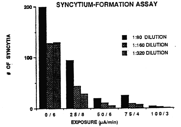
Figure 2. Results of a
representative reverse transcriptase assay. Six aliquots oGBP
the RF strain of HIIV-1 were exposed to different amounts .of
current for 3 or 6 minutes. A. significant decrease (p < 0.
005)from 0 current levels (0/3 and 0/6) in reverse
transcriptase activity is noted. However, the decrease is more
significant (p<0.0001) when virus is exposed to 100iA for 6
minutes.
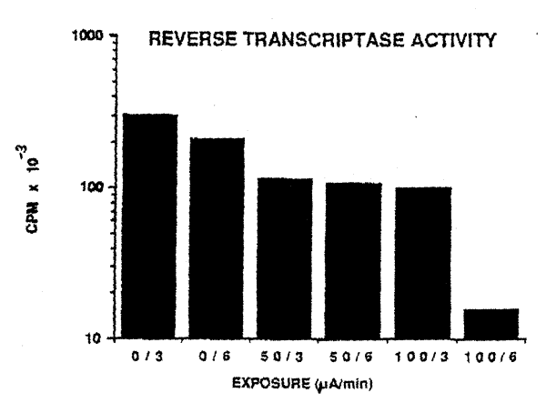
Table 1
Experimental Paradigm
Current (i.A). Time (Minutes)
0 1 4 8 12
25 2 4 8 12
50 3 4 6 12
75 2 4 8 12
100 1 3 4 12
Table 2
Effect of ELECTRIC Current on Syncytium Formation
% of O Current Control (A%)b
Current (iA) Six Minute Exposure
0 100 (0)
50 50 (-50)
100 35 (-65)
a = Value at I:160 dilution of
virus.
b = Value equals the mean of 3 experiments.
Table 3
Effect of Electric Current on Reverse Transcriptase Activity
% of O Current Control (A%)
Current (ia) Six Minute Exposure
0 100 (0)
50 56 (-44)
100 6 (-94)
a = Value equals the mean of 5
experiments.
The standard error of the mean in each case was less than10%
of the mean value.
Table 4
Effect of Eclectic Current onViability of Uninfected H9 Cells
(% Viable CeIIsa)
Length of exposure (Minutes), Current (iA) 0 3 6
0 96 94 6
50 98 95 98
100 96 97 93
a = At feast 200 cells counted in
hemocytometer field
Table 5
Effect of Electric Current on Temperature of Tissue Culture
Medium a ( degC) Length of Exposure (Minutes)
Current (iA) 0 3 6
0 19 19 19
50 19 19 19
100 19 19 19
a = The temperature was monitored
before, during and after exposure.
Results shown are end-point determinations.
REFERENCES
1. Sato PA, Chin J, Mann JM. Review
of AIDS and HIV infection Giobal epidermiology and statistics.
AIDS 1989; 3 Suppl.1:S301-7.
2. Centers for Disease Control.
Revision of the CDC surveillance case definition for acquired
immunodeficiency syndrome. MMWR 1987; 1 Suppl. 36:S1-15.
3. Thacker SB, Berkelman RL. Public
health surveillance in the United States. Epidemiol. Rev 1988;
10:164.90.
4. Klein RS, Friedland GH.
Transmission of human immunodeficiency virus type (HIV-1) by
exposure to blood: Defining the risk. Ann Int Med 1990;
113:729-30.
5. Oxtoby MJ. Epidemiology of
pediatric AIDS in the United States. In: Brain in Pediatric
AIDS (Kozlowski PB, Snider DA, Vietze PM, Wisniewski HM, eds)
1990:1-8
6. Broder S, Mitsuya H, Yarchoan R,
Pavlakis GN. Antiretroviral therapy in AIDS. Ann Int Med 1990:
113:604-18.
7. Perno CF, Baseler MW, Broder S,
Yarchoan R. Infection of monocytes by human immunodeficiency
virus I blocked by inhibitors of CD4-gp120 binding, even in
the presence of enhancing antibodies. J Exp Med 1990;
I71:1043-56.
8. Mitsuya H, Weinhold KJ, Furman
FA et al. 3'-Azido-3'-deoxythymidine (BW A509U): an antiviral
agent that inhibits the infectivity and cytopathic effect of
human T-lymphotropic virus type III/
lymphadenopathy-associated virus in vitro Proc Natl Acad Sci
USA 1985; 82:7096-100.
9. Quinnan GV, Wells MA, Wittek AE,
et al. Inactivation of human T-cell virus, type III by heat,
chemicals and irradiation. Transfusion 1986; 26:481-3.
10. Bisaccia E, Berger C, KIainer
AS. Extracorporeal photopheresis in the treatment of
AIDS-related complex: A pilot study. Ann Int Med 1990;
113:270-75.
11. Nara PL, Hatch WC, Dunlop NM,
et al.: Simple, rapid quantitative, syncytium-forming
microassay for the detection of human immunodeficiency virus
neutralizing antibody. Aids Res Hum Retrovirus 1987; 3:283-302
12. Cheng N, Van Hoof H, Bockx E,
et al. The effects of electric currents on ATP generation,
protein synthesis, and membrane transport in rat skin. Clin
Ortho ReI Res 1982; 17I:26472.
13. Frank G, Schachar N, Dittrich
D, et al. Electromagnetic stimulation of ligament healing in
rabbits. Clin Ortho ReI Res 1983; I75:263-72.
14. Eriksson E, Haggmark T.
Comparison of isometric muscle training and electrical
stimulation supplementing isometric muscle training in the
recovery after major knee ligament surgery. Amer J Sports Med
19?9; 7:159-71.
15. Stanish WD, Valiant GA, Bonen
A, et al. The effects of immobilization and of electrical
stimulation on muscle glycogen and myofibrillar ATPase. Can J
Appl Sport Sci 1982; 7:267-71.'
16. Pills AA. Electrochemical
information transfer at living cell membranes. Ann NY Acad Sci
1974; 205:148-70.
ACKNOWLEDGMENTS
Thanks go to Mrs. Agnes Geoghan for
her excellent secretarial assistance and to Dr.Gabor, Kemeny
for important technical help. Additional thanks go to Drs.
Frank Lilly and Philip Aisen for their constructive criticism
of this manuscript.
---
EXPERIMENTAL RESULTS
Overview: A non-flow vessel or cell
included a pair of platinum electrodes 1 mm apart inserted
into a well 1.56 mm in length and 8.32 mm in depth. The
non-flow vessel was connected to a direct current source
capable of creating an electric field at a constant voltage
and constant amperage. Into this well was laced a suspension
of the human immunodeficiency virus type 1 (HIV-1) at a
concentration of 1,000,000 infectious particles per ml. An
aliquot of approximately 10 ul of the virus suspension was
placed into the well. Thereafter, the viral suspension was
exposed to direct currents ranging from 0 microamps (uA) for
up to 12 minutes, to 100 microamps for up to 6 minutes.
Intermediate currents of 25, 50 and 75 microamps were used to
expose similar viral aliquots. After exposure of the viral
suspension to electric currents, the contents of the non-flow
vessel were removed and placed into sterile microtubes. 5 ul
of each sample were removed and diluted with 95 ul tissue
culture medium supplemented with 10% fetal calf serum (FCS.
unborn calf blood) In Experiment 1, the resuspended and
treated viral stocks were incubated with a human T
lymphoblastoid cell line named CEM-SS. This cell line, upon
exposure to HIV-1, forms syncytia (giant cells). It is well
documented that the viral titer (amount) used is directly
correlated with the number of syncytia formed. Therefore,
evaluation of infectivity of HIV-1 can be used with this
assay. In contrast, Experiment No. 2 used a differnet human T
lymphoblastoid cell line named H9. This cell line, in contrast
to CEM-SS cells, produces, upon exposure to HIV-1, many viral
particles. The amount of virus produced is proportional to the
amount of virus to which the
cells are exposed. Therefore, quantitation of viral particles,
or more commonly associated viral protein (in this case
reverse transcriptase), can be used as an index of viral
infection. In both assays, the CEM syncytia forming assay and
the H9 viral protein assay, similar type results were
obtained. That is, with the CEM cells, although syncytium
formation and quantitation is preferrable, one can quantitate
the HIV-1 associated protein (reverse transcriptase) activity
and conversely with the H9 cells, although reverse
transcriptase quantitation is preferred, one can quantitate
giant cell (syncytia) formation. Both of these assays are
widely used as reproducible measures of viral infection and
can be used to determine if alterations in viral infectivity
as a product of this electrical treatment can be detected.
Experiment #1
Approximately 100,000 CEM-SS cells
per sample were incubated with a treated or untreated
(control) viral aliquot for up to 4 days. The cells were
placed into microtiter plate wells and monitored for formation
of syncytia every 24 hours by microscopic observation. In a
standardized fashion, as it has been reported in the
literature and is currently being conducted in many
laboratories, the number of syncytia at 3 and 4 days was
determined. Table 2 summarizes the results from a
representative experiment using this assay. As can be noted,
the number of syncytia formed was inversely proportional to
the amount of electric current. That is, additionally, with
increased current (100 vs 50 uA) there was a reduction in the
number of syncytia formed. These results and those of
additional experiments using the CEM-SS cell line indicate a
consistent finding that electrical treatment of the RF strain
of HIV-1 attentuates the virus potential for inducing
syncytium formation in this cell line.
Experiment #2
A separate and independent assay to
determine the ability of electric current to alter HIV-1
infectivity using H9 cells was employed. The basic strategy
was similar to that used for the CEM cells with the exception
that the initial suspension of treated and controlled
(non-treated) viral stock was incubated with 100,000 H9 cells
for 2 hours at 37 degees Celsius. Thereafter, the cell virus
suspensions were further diluted to 5 ml in standard tissue
culture medium. The cell-viral suspensions were then incubated
for up to 14 days at 37 degrees Celsius with 5% carbon
dioxide. At 3 day intervals (beginning at day 2), aliquots of
cell suspension were removed from each sample. The aliquots
were centrifuged at 1,000 rpm for 5 minutes in order to pellet
the cells. After centrifugation, the supernatant and cell
pellets were seperated. The supernatant was cyropreserved for
subsequent reverse transcriptase assay and the cell pellets
were resuspended in fixatives and maintained in a tissue bank
for additional studies employing in situ hybridization and
immunocytochemistry to detect qualitatively and
semi-qualitatively viral infection by HIV-1. At the end of
each experiment, the supernatant samples from each of the
tests and time points were examined using standard reverse
transcriptase assay. The results of the representative
experiment are shown in Table 3. The results of this
experiment indicate the ability of HIV-1 to infect H9 cells is
attenuated by the magnitude of the electrical currents to
which the virus is exposed. Additionally, at lower current
magnitude, but with prolonged exposure time, attenuation of
viral infectivity is achieved. That is, analogous to the
results observed using syncytium formation and the CEM-SS cell
line, either increased current or increased duration of
exposure time was inversely proportional to the amount of
reverse transcriptase produced by the cell line.
In conclusion, these experiments
which have been repeated several times, and those using the
CEM-SS cell line, indicate at a statistically significant
level that direct electrical current at biocompatible
amperages for discrete exposure time intervals can attenuate
the ability of HIV-1 to infect normally healthy cells which
are susceptible to the HIV-1 AIDS virus.
---
Electrified Intrauterine Device
GB 2,238,725
6-12-1991
EC: A61F6/14B2;
A61N1/05V IPC: A61F6/14; A61N1/05; A61B17/42 (+4)
---
Electrical Generally Rounded Canopy-Like
Contraceptiv e Devices
IN 171,695
1992-12-12-1992
EC: IPC: (IPC1-7):
A61F5/46
---
Contraceptive Device Comprising
Electrified Vaginal Ring
GB 2,213,385
8-16-1989
EC: A61F6/08 IPC:
A61F6/08; A61F6/00; (IPC1-7): A61F5/46
---
Contraceptive Devices
GB 2,206,799
1-18-1989
EC: A61F6/08 IPC:
A61F6/08; A61F6/00; (IPC1-7): A61F5/46 (+1)
---
Electrical, Generally Rounded Resilient,
Canopy-like Contraceptive Devices
USP # 4,770,167
9-13-1988
EC: A61F6/08 IPC:
A61F6/08; A61F6/00; (IPC1-7): A61F5/46
---
Contraceptive Method & Device
Employing Electric Forces
IN 164,985
7-22-1989
EC: IPC: A61F5/00;
A61F5/00; (IPC1-7): A61F5/00
---
Contraceptive Device
GB 2,195,253
4-07-1988
PORTER, Joseph; KAALI, Steven
EC: A61F6/14C; H01M2/10C2 IPC: A61F6/14; H01M2/10;
H01M2/34 (+4)
**---**