George Merkl -- Chondriana & Life Crystals -- Synthrophic
Transducer

**[rexresearch.com](../index.htm)**
---
**George MERKL**
**Chondriana & Life Crystals**
---
**1. [Biographical Info 1](#zoominfo)** **2. [Biographical Info 2](#bio)** **3. [Life Crystals Canada, Inc.](#lifextls)** **4. [Warren York: The Genesis Factor](#york)** **5. [George Merkl: Syntrophic
Transducer](#merkl%20syntr)** **6. [Perry Chapdelaine, Sr .: Life
Crystals & Chondrianas](#chapdelaine)** **7. [Dan York Email](#danyork%20email)** **8. [Warren York Email](#york%20email)** **9. [Steve Mills : George Merkls Life Crystal
Discoveries](#mills)** **10. [Dennis L. Myers : Pleomorphism](#myers)**
**11. [G. Merkl : Sacred Geometry](#sacrgeom)**
**12. [YouTube Videos](#youtube)** **13. [Dr. George Merkl : Sumer-Tech --
Cosmic Bio Machine](#sumertech) [ Text & PDF ]** **14. [Patents](#patents)**
---
**Dr. George Merkl**
---
[**http://www.zoominfo.com/people/merkl\_george\_56848950.aspx**](http://www.zoominfo.com/people/merkl_george_56848950.aspx)
George Merkl is a nuclear physicist and president of Life
Crystal Incorporated in El Paso, Texas. He has conducted
research for the past 30 years in his own research laboratories,
and holds more than 40 U.S., and hundreds of international
patents on his discoveries and inventions. Dr. Merkl is listed
in "Who's Who Among the Pioneers in Science Today". His latest
discovery is the present discovery particle biochemistry and the
secret of life. He is the author of "Inner Space (Unified
Theory)", and he has discovered a new treatment which can cure
AIDS, cancer, and many other degenerative diseases.
---
[**http://www.consumerhealth.org/tothealth/tot01/29.html**](http://www.consumerhealth.org/tothealth/tot01/29.html)
GEORGE MERKL, PhD (El Paso, Texas) -- George Merkl is a
nuclear physicist and president of Life Crystals Canada of
Oliver, BC, where his crystal-based health products are made. He
has conducted research for the past 38 years in his own research
laboratories, and holds more than 40 U.S., and hundreds of
international patents on his discoveries and inventions. Dr.
Merkl is listed in Who's Who Among the Pioneers in Science
Today. His latest discoveries deal with chlorophyll crystals,
crystals of consciousness and fractal perception. He is the
author of *Inner Space* (Unified Theory) and *Whispers
of the Cosmos Begin to Blow*.
---
**Life Crystals Canada Inc.**
(250) 498-2228
Ray De Blasi, Vice President
Products based on discoveries by Dr. George Merkl about a new form
of life that destroys cancer and repairs organs
---
[**http://www.textfiles.com/bbs/KEELYNET/BIOLOGY/genesis1.asc**](http://www.textfiles.com/bbs/KEELYNET/BIOLOGY/genesis1.asc)
**Preface to the Genesis Factor**
In mid-summer of 1990, Warren York informed us of a most
interesting man who had developed almost a new form of science
single-handedly. His name is George Merkl.
After speaking with George on the phone several times, we were
so ecstatic that a trip was planned over a weekend to visit with
him.
Three of us made the trip by air and what we found exceeded all
our expectations. George proved to be everything we hoped
for and we learned much new information. We also took some of
our papers and video tapes so he could see where we were coming
from.
The primary discovery George had made years ago was a principle
which he termed SCROLL WAVES. These waves are extremely small
and can be likened to Aether or Zero-Point-Energy moving
in continuous spiraling patterns.
To quote from George's privately published book "Inner Space":
"The photon is not a constant but is energy based on DECAYING
spinning wave resonance. Now when an energy exchange takes place
between two electrons (or particles), the electron may move with
a velocity.
When the particle has absorbed or attained enough energy, it
may get rid of that energy by emitting it in a full or
partially MUTILATED wave form.
But a second particle or electron may REABSORB THE SAME ENERGY,
whereas BOTH will SPIN and RECOIL IN OPPOSITE DIRECTIONS.
The direction will be determined by the recoiling photons. The
photon transfer will be responsible for the force set up between
the pair of electrons. The photon is energy in wave form which
acts as a force field.
This moving wave form can convert to current as the force field
is being produced when the photon RECOILS WHILE IT IS SPINNING.
This force is related to the inverse square law for the force
of attraction and repulsion between two interacting
particles through energy exchange."
George has many patents in several fields, with the majority on
new chemical processes.
**THE GENESIS FACTOR**
**Introduction by Warren York**
Up to this point I have covered the unifield of scalar
technology covering up to and including relativity. I have
talked about the relations of scalar technology with gravity, 3D
time and space, and the phenomena spectrum.
I had planned to talk about scalar technology and free energy
this issue. In the first issue I had stated scalar technology
would open doors to new frightening and fantastic areas never
before attempted in depth all under the same roof.
Well, thanks to Dr. George Merkl who is a part of our loose net
group or team we have crossed over the fantastic into the
unbelievable. I knew after I had talked about free energy and
scalar technology I would have to explain it's relationship to
what man calls the life element [Genesis Factor] or life itself.
This is a touchy area and one that should be approached with
caution. George -- who does not like to be called DR -- has
broken the code of life itself. Unlike Dr. Frankenstein, George
has achieved it in an acceptable way. I cannot go into great
detail at this time for the work must be checked and double
checked to make sure what we are observing is indeed taking
place.
We are in the process of recording the documentation for future
release. We have reached the point that the test must be brought
under control instead of uncontrolled as lack of proper
equipment and lab conditions are forcing us to try and narrow
down very exciting data that is slipping through our fingers at
the moment.
If anybody out there can locate such needed equipment or proper
funding to run a full-blown research lab and facility please
contact me at the address below. We are putting on videotape
what uncontrolled data we have learned but even that is hampered
by lack of proper equipment.
We will make do until better is available and I am sure when
you see the video docs you will find it hard to believe. Dr.
Henry C. Monteith who is also a part of our research group had
been down here last weekend to see what we have and was very
impressed on what George had discovered.
George's discovery alone can turn the world conditions around
and we can once again have a clean and healthy planet to live on
and offer our future generations. This new learned info can also
help man as he ventures out into space to set up new homes and
work places.
This research lab I am trying very hard to make a reality will
benefit all mankind. A think tank for mankind [ not just a corp.
] which will generate new fields and jobs. Solve problems not
yet thought of and bring together some of the best free thinking
minds in the world to do something about tomorrow today.
Dr. Monteith alone wished to develop a new concept in
microscopes. His project is known as the Litraonics Microscope
and can show the structure of an actual atom unlike any
resolution done by MIT or IBM to date. I will have photos taken
of an atom with this equipment and more information on his
progress about the device in future issues.
Also Mike Windell who is a part of our group has developed our
first prototype of scalar communications. It is known as an
advanced telecommunication project. The prototype is being
developed as a demo to be presented to METS out of Florida for
possible future funding for future development.
The unit will transmit a signal through any kind of shielding.
We are working with ranges up to one mile so far without any
problems that so ever. The units are portable and mobile. Mike
has discovered a very important element in any scalar field
generation. In order to have true scalar generation one must
generate a " Shear Effect ".
I have not gone into this in any of my past articles for this
is new info. Also the design of the scalar coil has changed
drastically since the original release here.
As I said all data is being put on video and sure there
will always be people who say we faked it but we have witness to
backup the tapings.
I'll let George tell you in his own words now about the Genesis
Factor or what life actually is itself and how it is generated.
Keep in mind George is a nuclear physicist with over 400
patents to his name. George will talk about scroll waves. Scalar
is a process where scroll waves is the actual Aether in motion.
This motion is known as free energy or life energy itself. It is
all related to what we have talked about in the pasted articles.
I wish to remind anybody who needs to contact any person in our
active group please contact me through our New mailing
address listed below. At this point we are in need of the use of
an electron microscope to gain needed data on a new life form we
can't match up to any known so far. They are still in the embryo
stage at the printing of this paper.
On a microscopic scale they have rib cages, internal organs,
eyes, mouth, digestive track and what looks like a hand.
We also have on videotape crystal clones [ that growing
crystals but not alive ] on a micro scale of what looks
like a complete pine tree branch or fern, insect wings and other
fantastic events.
---
[**http://totse2.net/totse/en/fringe/fringe\_science/genesis1.html**](http://totse2.net/totse/en/fringe/fringe_science/genesis1.html)
**SYNTROPHIC TRANSDUCER**
**by**
**George Merkl**
Discovery of the atomic wrench by myself, George Merkl,
underlines my earlier work of transducing scroll waves (free
energy braiding into photons) to a higher energy level to
control chemical bonding.
Scroll resonant energy leaves its signature on everything
throughout the whole universe including all forms of life.
RESIDUAL OUTCOME FROM THE THIRD COLD FUSION PROCESS:
According to the law of quantum mechanics the electron between
two carbon fluctuates between positive and negative carbon. To
assure the stability between two carbons in the diamond lattice,
I proved that the carbon in the diamond is indeed in the
positive and negative ionic state, and is also responsible for
the hardness.
Since polarity is resonating back and forth, it seems
non-polar.
The fact that I was able to make diamonds of both type one and
two at atmospheric pressure by pairing homopolar carbon ions
also proves that diamond is homopolar!
My real interest was to introduce single ionic nitrogen to form
carbon bonds by an exchange reaction in the lattice substituting
carbon isomorphously.
These carbon nitrogen bonds form paramagnetic centers, and
convert ortho hydrogen to parahydrogen with paramagnetic
properties simply by transducing an energy level via resonance
from scrolls to reverse the spin of the proton!
I used the following reaction for this purpose:
3 CH4 > C4+ +12H-
12 Li +3C4+ >3C4- +12Li+
NH3 > N3- + 3H+
The above CN bond spacing was 10% over carbon to carbon bond.
According to quantum mechanics the probability of nitrogen
oscillation frequency in the molecule will be the function of
the superimposed frequency which is generated by the oscillator
crystal excited by the scrolls.
The nitrogen is stationary and once excited by its transition
frequency in a giant molecule of carbon, the energy is
transferred and the carbon bonds have to move or oscillate.
Therefore, the oscillation of the crystal transplants its
energy to form chemical bonds, or transduces energy from scrolls
sufficient to reverse the spin of a proton to form para proton.
That shall be the base of a clean industrial revolution paving
the way to save this planet.
[FIG 1]
Let's make a detour from this major technological breakthrough!
Recently I discovered that the powerhouse I developed to
transduce energy naturally had it all along.
Such a photo transducer power house is common to all living
organisms including plants, microbes, and human cells
(including brain cells).
As we know it as the chlorophyll family --- all are dependent
upon scrolls, absorbing it from our atmosphere and utilizing it
as we know is done in photosythesis.
[FIG 2]
After thirty years of fruitful research, and research of plant
life in the last five years, I do have ample proof that
scrolls are responsible for the basic functions of life.
If we drastically change our atmospheric condition by changing
conductivity, plants will be deprived of energy and will die!
Scrolls are responsible for pumping the fluid into the
capillaries. This is directly related to moisture content,
static charge, and conductivity of the atmosphere.
Life first evolved from the sea because the depths are a soup
of scrolls where water is saturated under pressure.
This is the reason for the spiral or vortex fingerprint on
sealife, "The very form of the free energy" scrolls. In search
for a more nature-made phototransducer, I found many links to
nature's chemistry by prediction.
For example, in a heteroautotrophic system, sugar was reduced
to alcohol, and CO2 + H20 were synthesized to sugar, thus
completing the cycle.
In addition to chlorophyll the first two photo transducers I
tested were coffee and theobroma oil. I chose to study the
latter over cocaine because I used them in phototransducing in
the fermentation process. I did not want contamination by the
nature of cocaine.
I found that both products are capable of
phototransducing energy -- the maximum results having been
achieved between twelve AM and three PM.
It was not hard to determine how drugs speed up biological
processes and burn out the cells including that of the
brain! The energy they transduce not only depletes the scrolls
from the blood stream but overloads the cell circuits.
A chlorophyll pair absorbs the photon quantum at 670 nm. My
atomic wrench output is at a shorter wavelength and a higher
frequency of oscillation.
The following are some of the nature-made energy transducers:
PROCAIN, QUININE, HEROIN, METHADONE, CODEINE, COCAINE,
CAFFEINE, NITROUS OXIDE (N-O-N EXCEPTION), ACTIVE
VITAMIN B TWELVE, REACTIVE CYANOCARBON ETC.
They all carry the carbon nitrogen fingerprint!
Utilizing the phototransducers, I was able to raise
the alcohol level of wine produced by solar fermentation
to 80 proof containing only natural pure solar distilled
grapejuice.
I would like to add here that during the drought in June 1990
in El Paso, Texas, the humidity level dropped to 6% which
drastically reduced the conductivity of the air as well as the
static charge of the air!
As a result most plants went into dormancy; the
phototransducers in the chlorophyll stalled due to the lack of
conductivity; all fruits stopped growing in spite of extensive
irrigation.
Except on plants whose surroundings were altered by raising
local conductivity artificially, I also found out that the
capillaries of the Persian Lilac grown, were fewer but many
times larger in diameter, due to lower flux density produced by
the weak fields.
This phenomenon is directly related to the conductivity and
static charge. These comparisons clearly showed the opposite
effect on the same root section during the wet season here in
1989 when conductivity and static charge was above average.
[ FIG 3 ] THE POWERHOUSE TRANSDUCER IN THE CYTOCHROME [
evolution of life ]. WITHOUT THIS ENGINE, LIFE COULD NOT
SURVIVE. IT'S FUEL IS THE SCROLL.
Now we have seen the syntrophic phototransducer are similar to
autotrophic and heterotrophic transducers which nature built
within the living organism, these are of course, unquestionably
prerequisites to life formation and existance.
The leaders of the world with total ignorance, miscalculating
the catastrophic consequences while tampering with our
atmosphere, which their advisors know nothing about.
This planet could re-cycle too soon if the world continues to
ignore the facts!
We have seen how the C-N-Bond, semi-absorbed, promotes
paramagnetic sights where ortho to para conversion takes place.
By upsetting the ortho-para ratio the hydrogen will lift ortho
delta positive link to the delta positive atoms such as halo
delta positive, CH delta positive, HWC delta positive, and so
on.
This opens the way to "Transport Reactions", a new branch of
science even the greatest person could never dream of. (MAJIC)
(Transporting suboxides coupled to para hydrogen, vapor phase at
low temp).
I utilized this new technology to build alternate rows of
nitrogen-doped carbon atoms where the layers of 111 oriented
surfaces formed a superlattice. (All 111-100 and 110 faces were
constructed from the bent carbon rings of graphite).
By using the paraproton transport reaction technology, I
pioneered new forms of metallic carbons, diamonds etc., with
different D spacings, but I synthesized hundreds of exotic new
materials which are perhaps a hundred years ahead of time.
The important facts are that some of these materials could
solve many of the worlds problems today, for instance, a
pollution-free world; or harnessing of the sun's clean energy,
by capturing the free energy (Scrolls).
My syntrophic transducer is not only able to stimulate solar
fermentation, but could also produce electric current and free
hydrogen through transducing the lower level energy.
Chlorophylls have different geometries of antenna. This
produces different patterns of isobars, as the resonant molecule
absorbs or emits it's transduced photon energy.
The three dimensional field so produced follows the
scroll pattern sideways, which is similar to my three
dimensional field produced in my first cold fusion process in
the sixties.
Electrons excited by the scrolls are different from electrons
in the normal state as verified by their fingerprints on the
EPR. spectrum. Through this, energy couples with the nuclei
orientation of the nuclei differ with respect to an external
field.
The larger the number of excited electrons, and their spectrum
proportional to their number, "The higher, the narrower the band
will be".
Scrolls determine the size of the photon, that is absorbed by
the spin-aligned electron or proton, this alters their position
correspondingly.
Thus, their energy level is transduced to the absorption
frequency to match the absorption frequency of the host electron
or proton.
Changing the direction of spin on a proton depends on the
strength of the external field, and can also change the
absorption spectrum due to spin polarization.
"A strong North pole of the proton (Blackhole) can suck in
countless scrolls by their South poles and reverse the spin. By
forcing the position of the proton to the opposite attracting
position via scrolls and by reversing the orientation of the
proton, ortho proton can be converted to para proton.
In the atomic wrench, the nitrogen and electrons result in
hyperfine interaction. The hyper-excited carbon nitrogen
transducer can lase immense photon flux and subsequently
transduce enough upshift of the frequency to reverse the proton
spin.
"FREE ENERGY" THE SEED OF LIGHT":
"A three dimensional vortex, performing three dimensional
motion, inverting thru it's poles back and forth and changing
signs constantly."
The scrolls form strands with matching frequency of oscillation
and equal wavelength. These strands of scrolls braid into photon
vortexes. 918 pairs of photons (Magic number) feed the vortex of
an electron.
Again a 917 pair (5 pairs off) electron vortex copies the
genetic trait to form the proton, and 918 electrons form the
neutron. (See: Inner Space 1968, balanced).
Every time an atomic vortex inverts through a blackhole the
scrolls form a coherent field followed by pole splitting which
then reverts through a white hole followed by an incoherent
field.
Each absorbed scroll adds up to increase the mass of the host.
However due to the increased mass, the spin will change on the
host, followed by a change in wavelength and frequency of
oscillation.
[ FIG 4 ] FREE ENERGY [ SCROLLS ] AT WORK!: The plasma membrane
of the living cell is permeable to ions that are driven by the
self-induced field generated by free (scroll) energy.
The net result is an electrical potential between the inside of
the cell (-) and the outside of the cell (+). Sodium and
chlorine ions are responsible for the conductivity in the plasma
medium. (Reference material concerning physics. See Patent: USP
3,993,595).
[ George Merkl -- USP # 3,993,595 -- Activated aluminum and
method of preparation thereof (November 23, 1976 )
Abstract -- Reactive aluminum consisting essentially of aluminum
having a purity by weight of at least about 99.99% permeated by
a liquid metal selected from mercury, gallium and gallium/indium
alloys. The permeation can be accomplished at room temperature
and atmospheric conditions. The reactive aluminum exhibits
greatly altered physical and chemical properties as compared to
the aluminum before permeation. These new properties include a
uniform alignment of atomic grain boundaries and domains and a
multitude of channels defined in the reactive aluminum. ]
The cell membrane along with its plasma, acts like a condenser,
and is negatively-charged inside with respect to the outside
which is positive.
The condenser membrane is charged by the scrolls (static charge
of the air). The potential difference varies between 40 to 80 mv
depending on the scroll energy density.
Such free energy density will vary with the incoming cosmic
rays, and also with atmospheric conditions such as
pressure, moisture content, static charge, etc.
"THE GTP AND ATP ARE THE PRIMARY ENGINE OF THE LIVING CELL"
In the case of G.T.P. the Guanosine is the energy transducer
and emitter while the Triphosphate is the storage battery. The
free energy charging the cell membrane (from static charge like
a condenser) on discharge self-induces it's field to which the
ions are attached and flow.
When the cyclic ring enzymatically cleaves onto the
G.T.P., the battery releases energy and generates a reverse
field. This action counters the self-induced field on the cell
membrane, and becomes the driving force of the ion flow across
the cell membrane.
This mechanism controls the ionic flow by switching it on and
off.
On each cycle the electrical properties of the membrane change
(depending on the nature of the signal) and give rise to nerve
impulses.
The increase or decrease of the cell permeability comparable to
the variation of domain cross-section in the above given
reference patent and is of course directly proportional to the
free energy and also to the ENVIRONMENTAL CONDITIONS.
"In general, all biological activity strictly follows the
weather pattern", and it's being dependent on the unmolested
atmospheric condition.
I hope you all realize the scope of this discovery,
underscoring your general feeling or existence which is of
course influenced by tampering with your environment.
As the cyclic G.M.P. opens during hydrolysis a water
molecule inserts into the ring, being triggered by a light beam
from below my incubator.
Reacting yeast and plant cells in separate experiments (My
solgraft process) in a G.M.P. and A.T.P. soup, the experiment
turned out as predicted. -- The G.M.P. depolarized the cell
membranes by field.
The self-induced field on the cell membrane generated by the
static charge of the air was cancelled by the G.M.P.s
gravitational field induced by sunlight!
The resulting decrease in ion flow across the cell membrane
retarded the self-induced field and the potential difference,
thus opening the way to communicate in and out of the cell's
genetic material!
By (Solgraft) assembling, disassembling, grafting,
transplanting within or outside of the cell and by architecture
of R.N.A. and D.N.A., I began grafting G.M.P. and A.T.P. to
proteins which led me to grafting alternate transducers to
acceptor sights.
When we are talking light-induced hyperpolarization we should
also talk about spin control which is controlled by the external
field strength.
This in turn, controls the ion flow. I extracted sub-units of
RNA-G.M.P. (by isol process).
After purification I hydrolyzed the crystals in distilled
water, and I observed that the crystal strongly attracted to the
polyetheyne wall charged by static.
The mono crystal disintegrated into countless macro crystals,
always forming hollow spherulets in water!
These spherulets possessed strong magnetic force! In other
words, crystals coupled like tiny magnets to form what one might
call "Supercrystals".
"I also observed and experienced levitation". I placed a one
inch diameter incubator with 1 ml genetic mix sitting on a glass
plate and passed a beam light thru it from below.
As I added the G.M.P., the incubator levitated a few mm
above the glass plate. I moved the incubator away, at least
fifteen times, and it kept on moving back and lined up with the
beam of light.
By sliding the incubator it felt like moving a repelling
magnetic pole. This gave me the clue that there are anti-gravity
interactions within the living cell, a phenomenon I have known
long since it has existed with plants.
I placed my synthetic soup of RNA and DNA into my incubator, I
observed that within twenty-four hours it organized into it's
normal hair-like structure.
It appeared that the sub-units of the RNA and DNA had their own
field and assembled accordingly.
I called my first synplant cofina because I derived its genetic
part from coffee.
Cofina consists of a single capillary plant whereby the
nutrients are delivered to the top where the budding developed
via.
The size of the Mono capillary (length) is determined by the
self-induced field generated by the free energy! Once the
capillary reached its height (the peak of the fluxlines) the
genetic soup oozed out, and all the G.M.P. moved to the surface
forming a unisphere.
(I observed the clear transparent sphere of genetic soup).
Within twelve hours the brown bundles branched out forming the
flower that carried the genetic code for the next generation!
I harvested the abundant crops and germinated them in water and
nutrients. The thousands of macro seeds or clones (Units) began
to germinate, growing first their roots.
Within thirty-two hours they were grown to the mirror image of
their parent. The seeds are in the sub-micron range and carry
their genetic code. I want you to understand that this is not
putting a patch on the double helix!
"THE MAIN THRUST HERE OF COURSE IS TO HARNESS SOLAR POWER"
I already engineered microbes and phototransducers that
liberate hydrogen from water; however most importantly, I
recently extracted genetic materials from pollen and I cured my
hyper-allergy that tortured me for thirty years!
With this solgraft process it is feasible to cross-graft
genetic materials between microbes and plants, replacing the
transducers on the RNA or DNA with synthetic ones.
It is perhaps tempting to call Cafina and Tina inorganic life
because it contains organic materials and so closely resembles
grain and domain alignments.
In conclusion genetic materials can be easily produced,
reconstructed, or transplanted and grafted at ease by the
solgraft process.
[FIG 6]
[FIG 7] LIGHTHOLES -- gencrystals form a hollow unisphere due
to their magnetic properties. The surface crystal layers of the
unispheres absorb light and turn black, except at their poles,
as light passing through them creates a vortex of light.
The absorbed ligh by the surface crystals is then transduced to
higher energy level.
[FIG 8] Static field pumps the ion flow in opposite directions
across the cell membrane and produces a self-induced field. This
is comparable to the scroll fields of the roots of the plants,
whereby driving the fluids into the capillaries is directly
proportional to the static charge and the conductivity of the
air.
By realigning the grain of an ultra-pure aluminum, the magnetic
moments will couple, forming linear domain capillaries. The
aluminum will acquire magnetic properties.
The free (static) energy will pump ions in the opposite
direction by micro capillaries. This self-induces a strong
magnetic field which is comparable to life process.
[FIG 9] (Contains genetic soup, held in spherical form via
magnetic fields generated by genetic sub-units)
[FIG 10]
[FIG 11] An inorganic product that grows like crops and
resembles living plants. Its growth rate is directly
proportional to the free energy (Static charge of the air), and
to the conductivity of the air -- the exact same criteria that
are prerequisites for ALL FORMS OF LIFE!
[FIG 12] [SHEET A] SYNTHESIS OF LIFE BY GEORGE MERKL
---
****
**Vinny Pinto****Excerpt from : Syntropic Antioxidative
Microbes (SAM) -- a Unique Class of Probiotic Beneficial
Microbes**
**Dr. George Merkl and his
Solar-Fermented Life Crystals and Sumerian Elixir Products**
**by Vinny Pinto**
I first heard of Dr. George Merkl and his exotic nutritional
supplements -- which were then marketed under the names Life
Crystals and Sumerian Elixir, and later under numerous other names
as well -- in the mid-1980s, when a small mail-order nutritional
supplement vendor in northern Wisconsin from which I occasionally
purchased products started listing his two products in their
catalog and also started distributing marketing pamphlets making
some very wild claims for Dr. Merkl's two products. I purchased
his strange nutritional supplement products occasionally
throughout the mid and late 1980s and more frequently throughout
the 1990s. Eventually, by the mid-1990s, I became acquainted with
two persons who had worked closely with George Merkl for many
years in developing and producing his exotic nutritional
supplements, and, over time, I heard a number of fascinating tales
from them about Dr. Merkl and his products, which, by then were
being marketed under a variety of brand names, including Life
Crystals, Sumerian Elixir, Sumer-Tech, Sumerian Drink, Renaissance
Drink, Renaissance Beverage, Vida Force, Vida Source, Vida Lyze,
Gaiandriana and Aquagaia. It has been estimated by observers of
the fringe nutritional supplement marketplace that at the height
of their popularity -- which would be from roughly 1982 to 2003 --
many tens of millions of dollars worth of Dr. Merkl's products
were sold in the US and Canada and also in over 48 other
countries, often accompanied by claims that the products would, in
short order, cure everything from diabetes and heart disease to
cancer. These extreme and blatant -- and almost entirely
undocumented and unverified -- health claims for a product that
had never been approved for therapeutic drug use, along with
Merkl's uncanny ability to manage to continually antagonize and
run afoul of regulatory agencies -- led Dr. Merkl and some of his
distributors into repeated troubles over the years with the FDA
and Health Canada, and with several other government regulatory
authorities across the world.
Dr. George Merkl was born and raised in the Soviet Union in the
early 20th century, where he earned a PhD in physics. In the wake
of some serious difficulties with the Soviet authorities in the
1940s just after the end of World War II, he emigrated to the USA
in the 1950s, settling primarily in the El Paso, Texas area. He
reportedly worked briefly for the US Naval Weapons Laboratory in
the field of nuclear weapons research and then went into
partnership with a few other PhD-level colleagues in forming a
private R&D laboratory which primarily performed contractual
R&D services for the US Naval Weapons Laboratory and for other
defense-related sectors of the US government; much of his research
work was still apparently in the realms of nuclear weapons
development and the design of nuclear reactors for use on
submarines. He often claimed in later years -- when he had shifted
his focus to the field of esoteric nutritional supplements -- that
he had been awarded over 400 patents between 1955 and 1980, and
that many of them had been immediately classified as top secret by
the NSA due to their applicability in defense-critical areas.
Dr. Merkl was badly injured in at least two accidental laboratory
explosions during the 1960s and 1970s, and one of them also
reportedly left him with severe plutonium poisoning due to
inhalation of airborne plutonium particles. Concomitantly, he also
developed several chronic and severe health problems commonly
associated with aging, including heart disease, and it is safe to
assume that his earlier injuries and the plutonium poisoning only
greatly exacerbated these chronic illnesses. In the mid-1970s, Dr.
Merkl suffered several severe heart attacks, and in the wake of
his last one, apparently in early springtime of 1977, he was
essentially sent home from the hospital by his doctors to die;
they had reportedly advised him that his heart disease was beyond
help and that he likely had only weeks to live; he also reportedly
had rather severe bowel cancer at the time, with at least one
large cancerous mass in his lower bowel. Now, this is where the
story gets weird and where the fun begins....
Merkl reported in later years that he had several mystical
experiences in those weeks after he had been sent home to die in
1977, and most of these experiences seemed to happen at night,
during sleep. He later claimed that angelic beings had come to him
during these mystical experiences, and had told him that it was
not necessary for him to die from his illnesses, and they offered
to guide him along the steps to a speedy recovery. Merkl reported
that he accepted their offer, and that he was, in short order,
instructed to go out to the field his lower backyard -- it
happened to be early springtime -- and to carefully cut the
pre-blossom rosebuds off the wild rose vines growing there, and
was advised to collect the liquid sap that would emerge from the
cut tips of the plant stems over the next few days. He was
instructed to process this small quantity of liquid in a modest
and simple alchemy-like process, and was then guided to drink it.
He was, within a few weeks time, cured of his heart disease and of
the cancer, and of a number of other illnesses from which he had
also been suffering.
By mid-1977, once he had been returned to a state of good health,
Dr. Merkl was then reportedly told by his inner angelic advisors
that the process that he had been given to prepare the springtime
rose vine sap elixir, while it had been quite useful for him on a
one-time emergency basis, was not at all practical to adapt to
large-scale production of a healing elixir, and so they offered to
teach him an alternate method to create larger volumes of what
they claimed with be a very much similar nutritional supplement
elixir which would exhibit very powerful healing properties. The
process that his angelic guides taught him required him to procure
certain organic fruit juice concentrates (including grape,
blueberry, black cherry, raspberry and currant) from specific
sources and to also procure several dried organic or wild-crafted
teas (primarily chamomile, jasmine and oolong) that had been grown
only in volcanic soils in certain specified regions of the world
(primarily parts of western Central America and South America),
along with two or three proprietary ingredients, and to ferment
them for several months in a strange rooftop glass-enclosed
apparatus -- which he eventually came to call a solar reactor or a
solar still -- based upon a design that they had given to him, and
his guides further specified that the rooftop solar reactor had to
be positioned to allow maximal sun exposure. Merkl later, in both
lectures and in some of his writings, often referred to his solar
fermenters as syntrophic transducers, for he felt that they, and
the process of fermentation therein, lent powerful syntropic
properties to his products. He once referred, in a lecture, to his
solar fermenter or solar reactor in the following fashion "My
syntrophic transducer is not only able to stimulate solar
fermentation, but could also produce electric current and free
hydrogen through transducing the lower level energy. ..." In a
related 4-page article that he wrote in the late 1980s or early
1990s, entitled Syntrophic Transducer, Merkl also wrote the his
solar fermenter, aka syntrophic transducer, functioned by
"....transducing scroll waves (free energy braiding into photons)
to a higher energy level to control chemical bonding....Scroll
resonant energy leaves its signature on everything throughout the
whole universe including all forms of life...". Scroll resonant
energy leaves its signature on everything throughout the whole
universe including all forms of life.This concept, and terminology
are, of course, very much similar to, and in fact, almost
identical to, that employed by Dr. Terugo Higa (see the following
section), the developer of a SAM Type 4 consortia culture called
EM, in describing the syntropic or negentropic exotic energy
effects, which he called "wave energy" or "gravitational wave
energy" of his EM product between 1992 and 1998.
The result of this process was a mildly acidic reddish-brown
liquid with a not-unpleasant taste somewhat akin to that of the
old patent cough syrups of the early and mid-1900s. Merkl
eventually, by the early 1980s (if not earlier) started to market
this product as Sumerian Elixir and later as Renaissance Drink,
and, much as referenced earlier, over the longer term Merkl and
his associates and distributors marketed various versions of this
liquid under a number of other trade names as well; a large reason
for the never-ending parade of trade names was the simple fact
that Dr. Merkl seemed to be constitutionally unable to simply
market his product as a useful and nourishing nutritional
supplement, and instead, he apparently simply could not refrain
from making extreme health claims for his product, claiming that
it exhibited drug-like effects in healing a wide variety of
diseases. And, since he and his associates had never put his
product through clinical testing and clinical trials in order to
gain approval from the FDA and Health Canada to market it as a
drug, his bizarre and ultimately self-defeating tactic ensured
that he was constantly on the radar screens of the FDA and Health
Canada, and that he was continually running afoul of these
agencies and other regulatory agencies. Interestingly, most of the
Merkl products disappeared from the marketplace by 2003, and the
very last of the Merkl-inspired products seem to have disappeared
from the marketplace by the year 2006. As of today (it is now
early 2010), I am not aware of any products using Merkl's Sumerian
Elixir (aka Life Crystals, Renaissance Drink, etc.) technology
available on the market anywhere in the Western world.
A few years ago, in 2006, after I had developed some useful and
rapid non-culturing-type proprietary assay methods for determining
the presence of PNSB in liquid samples, I carefully searched my
storage cabinets and managed to find some old bottles -- dating
back to the 1980s and 1990s -- of Merkl's liquid product that had
been marketed under each of several brand names, and I subjected
the liquid samples to some tests in my lab. These tests showed in
short order that the liquid exhibited a pH below 3.9 and that the
acidity was largely due to lactic acid from fermentation, and my
proprietary PNSB assays (mentioned earlier) quickly showed that
the products contained very significant quantities of PNSB and
their metabolites, thus confirming my hunch that the microbial
culture that was found in Merkl's nutritional supplement product
was a SAM Type 4 consortium. (With this information, along with
some intuitive guidance from my own inner guides and angels, I was
then quickly able to determine the likely proprietary ingredient
that Merkl had used in creating his fermented elixir, and was
able, in short order, to brew several fermented products which
were very much like Sumerian Elixir (and, of course, Renaissance
Drink.)
Since I know a good part of the process that Merkl used in brewing
his primary product, which was the Life Crystals Drink (aka
Renaissance Drink), and also based upon some of the
characteristics (to be discussed below) of this product, it is
obvious that Merkl's fermented product did not employ commercial
cultures purchased from microbial type culture collection vendors,
and rather, the exact makeup of the SAM Type 4 microbial consortia
present in each of his batches of fermented product was determined
solely by the naturally-occurring microbes present in and on the
surfaces of the various natural ingredients that he used, along
with the unique array of nutrients and micronutrients available in
the organically-grown ingredients used in the formulation.
However, this led to some interesting twists and challenges when
it came to the marketing of his products, particularly the Life
Crystals Drink and the Sumerian Elixir, for each of these
nutritional supplement products contained a significant amount of
alcohol due to ongoing fermentation by wild naturally-occurring
yeast during the active brewing process.
While FDA rules allow nutritional supplements and foodstuffs to
contain up to 1% alcohol content and still be classified as
nutritional supplements or foods, in general, if any such product
contains over one percent alcohol content due to natural
fermentation processes, then, with few exceptions, the product no
longer falls under the purview of the FDA, and rather, it is
subject to the much stricter and harsher rules for the brewing and
sale of alcoholic beverages formulated by and enforced by the
Bureau of Alcohol, Tobacco and Firearms (BATF). Since most batches
of Merkl's basic primary products -- the Life Crystals Drink and
the Sumerian Elixir -- contained well over 1% alcohol, and most
often contained from 2% to 3.5% alcohol, this fact eventually came
to the attention of first the FDA and eventually BATF, and his US
production facility in El Paso, TX was eventually classified by
BATF as an alcoholic beverage brewery, and his products were
likewise eventually classified as alcoholic beverages that could
be sold only in liquor stores.
Had Merkl employed tighter control over the brewing process,
including use of commercially-available cultures available from
microbial type culture collection vendors, along with certain
other measures, he could easily have ensured that the amount of
alcohol present in these two products would have remained well
below one percent, most likely on the order of 0.2% to 0.5%, and
he could have avoided much of his eventual hassles with the FDA
and BATF.
---
[**http://www.arthritistrust.org/Articles/Life%20%20Crystals%20&%20Chondrianas/pg\_0001.htm**](http://www.arthritistrust.org/Articles/Life%20%20Crystals%20&%20Chondrianas/pg_0001.htm)
[**http://www.consumerhealth.org/articles/display.cfm?id=19990303163417**](http://www.consumerhealth.org/articles/display.cfm?id=19990303163417)
[**http://www.garynull.org/documents/arthritis/life\_crystals\_and\_chondrianas.htm**](http://www.garynull.org/documents/arthritis/life_crystals_and_chondrianas.htm)
[**http://www.friendsoffreedom.com/links01.html**](http://www.friendsoffreedom.com/links01.html)
**Life Crystals and Chondrianas**
**by**
**Perry A. Chapdelaine, Sr.**
*Published on: 4/1/1992*
"Medical data is for informational purposes only. You should
always consult your family physician or one of our referral
physicians prior to treatment" -- The Arthritis Trust of America
Article provided by: The Arthritis Trust of America. This is a
final report
The Roger Wyburn-Mason and Jack M. Blount Foundation for the
Eradication of Rheumatoid Disease, AKA The Arthritis Trust of
America, 7111 Sweetgum Road, Suite A, Fairview, TN 37062-9384
***Summary as of December 20, 1993***
The Rheumatoid Disease Foundation board voted to open-mindedly
investigate George Merkle's claim that he had discovered a new
form of life that destroyed cancer and repaired damaged organs.
He called this form of life Chondrianas. Apparently a mixture of
adenosine tri phosphate(ATP) and guanosine tri phosphate(GTP),
ribose, nucleotides, glucose, fructose and glucose phosphates,
under the right conditions, enticed this organism from where it
was hidden, in the human (or any life form), for an unknown
number of millions of years.
If the claims are true, then mankind, through George Merkl, has
apparently discovered its fountain of youth.
After reviewing (1) The Life Crystal Manual, (2) video tape New
Frontiers in Molecular Biology: Life Crystals Capturing the Sun,
and (3) Discovery, Part II, all purchased from Life Crystals,
Inc., I visited George Merkl at his home, in El Paso, TX,
finding him to be a sincere, engaging personality.
Several thousand dollars were sent to Life Crystals, Inc. for
both the Life Crystals mixture and Chondriana. The Chondriana we
received proved to be live gram-negative bacteria.
The Rheumatoid Disease Foundation then learned that physicians
in all parts of the U.S. and Canada had had a similar experience
in receiving live gram negative bacteria with their orders, and
not receiving Chondriana. Altogether thousands of dollars have
been spent for gram-negative bacteria for injections into the
human body, rather than the alleged beneficent Chondriana.
Dr. Merkle's response to our laboratory findings of live gram
negative bacteria in what was supposed to be his Chondriana
order was his vehement denial that he had sent any Chondriana to
anyone in the United States. As The Rheumatoid Disease
Foundation, as well as other physicians, took pains to insure
that money to purchase Chondrianas went directly to George
Merkle (Life Crystals), then, either of two conditions seems to
exist: (1) There are no Chondrianas, but rather live
gram-negative bacteria have been sold as Chondriana, or (2) one
or more of his suppliers are substituting gram-negative bacteria
for Merkle's Chondriana.
To clear up this mystery, I asked George Merkle if he would
send a sample of Chondriana, without further charge, to Lida
Mattman, Ph.D., a specialist in pleomorphic organisms, for
scientific study.
George Merkle agreed to do so, but no Chondriana has been
received more than a year later, despite several faxes and
letters reminding Dr. Merkle of his commitment.
Dr. Merkle may very well have what he claims, but he has not
seen fit to share these results with the medical or biological
community, so far as we know, to this date.
The major portion of this report was sent to Dr. Merkle,
requesting correction of any false data prior to submission for
publication.
***Life Crystals and Chondriana According to
George Merkl***
Which choice does one make when a treatment promises everything
and simply sounds too good to be true? How would one
discriminate between the genius who has seen through to the
heart of truth, and the con artist or self-dupe, who has merely
obscured further the nature of reality?
John W. Campbell, Jr., the editor and writer who twitted the
scientific establishment for their pompous airs and over-serious
pronouncements, and also the same person who almost
single-handedly formed the modern field of science fiction
entertainment, advocated a simple criteria; namely, ask the
question, "Does it work?"
This criteria, of course, is not always easy to apply, because
it involves the willingness to divest oneself of the need to
follow authoritarian leaders, to invest time and energy in
self-search and appraisal, and to think for one's self. This
latter criteria is not something we're exactly taught to do in
modern society, even when the course is labeled "Creative
Thinking," or even "Creative Science."
True geniuses are always outside the bounds of social
restrictions, at least in the paths visited by their thoughts!
Dr. George Merkl may very well be one of those unsung geniuses
quietly busy revolutionizing health, the world's food supply and
cost of energy.
He says, "Nourish the body; it will thrive for a time. If you
nourish the genes, it may thrive 100, 150 or 200 years.
His findings which he's titled "Life Crystals" and
"Chondrianas" are most establishment-shaking, if true.
Dr. Merkl and his team "Produced gem grade diamonds and made
them at various D spacing with brilliant luster and variations
in colors. They researched and made fundamental discoveries
related to cold fusion, transmuting aluminum-26 plus hydrogen to
aluminum-27 1/2 isotope." In their "second cold fusion reaction,
. . . [they achieved the ultimate by transmuting sodium,
silicon, and nitrogen, to titanium, iron, and manganese, while
releasing enormous amounts of energy [on a microscale]." Such
experiments led to development of Life Crystals, which, in turn,
led to discovery of microscopic, virtually intelligent
"Chondrianas." "In their third cold fusion experiment, the
researchers were able to advance far ahead of current
technology, and actually reversed the spin of the proton," a new
ability to control atomic particles which allows control of the
bonding energies in chemistry. This work set the stage for
creation of "synthetic transducers, and later to the natural
energy transducers, those chemical structures that use" a newly
discovered form of energy called "scroll" energy which is "free"
and promotes the life process.
In some respects, this scroll energy can be described as "the
breath of creation."
If these discoveries are true -- regarding the function and
value of Life Crystals and Chondrianas -- and their
interpretation of them even close to being correct, no one can
afford to ignore their implications and use. Like the
fantasy-figure, Superman, who, at a single bound, overtakes the
fastest engine of destruction and neutralizes it, these
researchers have seemed to abolish the need for pharmaceutical
industries, the complex of interacting agri-industry giants and
the constant search for cheap and clean fuel.
Their alleged astounding discoveries are based on application
of nuclear physics to the biology of life and, like every other
finding on the basic nature of reality, has seemed to cut
through the Gordian knot of health, food supply and energy.
Do you believe this?
Well, it's too good to be true, and so you must either be the
pessimist or the optimist. Possibly only by personal
experimentation will you be able to decide that it therefore
could not be true, or that it therefore must be true.
The reported discoveries are of such an order of magnitude that
one simply cannot afford not to investigate Dr. Merkl's
research, to try their developments and to make a decision
oneself, especially at the relatively low costs for doing so.
Why?
Well, let's follow The Life Crystal Manual available, along
with two video tapes, from Life Crystals, Inc., 5732 Kingsfield
Dr., El Paso, TX 79912, copyrighted 1992. All materials
reprinted from that manual are used with permission of its
author.
***Life Crystals***
All life depends upon adenosine triphosphate (ATP) and
guanosine triphosphate (GTP) which produces energy in
conjunction with the citric acid cycle.
The energy reactions depend upon normalized enzyme activity.
Therefore "all life is dependent upon properly formed and
concentrated enzymes which in turn are dependent upon healthy
deoxyribose nucleic acid (DNA) and ribonucleic acid (RNA) found
within the nuclei of our cells.
"By providing readily available ATP and GTP, it is possible to
ensure optimum energy levels necessary for cellular growth,
repair, and function."
Life Crystals provide concentrated ATP and GTP in the purest
form, with "the penta carbon sugars providing the four basic
building blocks of life in pure form."
When light passes through these Life Crystals, they emerge
polarized, and it is this polarized light that sets the stage
for the evolution of life!
There are two forms of Life Crystals: one form (consisting,
according to label, of ribose and nucleotides, 2% phosphates,
0.37 mg/ml including adeno tri phosphate and guano phosphate,
fructose 15%, glucose 15%, including fructose and glucose
phosphates, all solar extracts, natural products, no chemicals
or preservatives added) can be used sub-lingually, placing two
or three teaspoons (or tablespoons) per day under the tongue,
leaving it there for two or three minutes and then swallowing
it. It is also perfectly acceptable to drink several ounces per
day. This form is available for purchase in the United States,
as well as most of the rest of the world.
The other form is as an injectable, and in this form is
available in the rest of the world, not the United States.
The advantage of the injectable is that the body will respond
faster for cellular and genetic growth, repair and functioning.
While it is said that there are more than 4,000 patients who've
used either the Life Crystals or Chondrianas or both, little
clinical data seems to be easily available, at least so far to
this writer. A small number of anecdotal medical case histories
supplied to The Rheumatoid Disease Foundation by George Merkl,
in Spanish, on partial translation did not seem to fit the
exacting standards necessary for unequivocal findings. However,
the alleged improvement (or cure) factor seems to be so huge and
should be so obvious that perhaps clinical data will be useful
only for those who must have such data -- or to satisfy FDA
requirements.
As claimed from other than medical case histories, one person,
George Merkl himself, claims that he had an incurable mixture of
carcinoma and sarcoma in his hip, which is wholly cured from
Life Crystals and Chondriana. He also had a serious heart
problem, which is now wholly healed. His hair is turning dark
from gray, his skin lacks the usual aged cross-linking signs,
and Leydig Cells have been restored and he and his wife, beyond
the normal age of childbirth, have had a child.
"If one could repair and normalize DNA and RNA function
quantitatively as well as qualitatively, then it would be
theoretically possible to postpone or even to some degree
reverse the aging process by preserving cellular respiratory
function. . . . it may now be possible to nourish DNA and RNA
structures by providing the building blocks of these structures
to the body. . . Nourish the body and it will thrive for a time,
nourish the genes and it may thrive for multiples of that time.
. . .With properly functioning enzymes, the body takes defensive
measures against toxins and repairs any former damage. A
disorder of any kind can be rectified by restoring enzymes under
suppression. Properly functioning enzymes not only brings
recovery but a measure of rejuvenation as well. More
importantly, an ancient, prehistoric life form has been brought
to life and replicated with a more concentrated form of the Life
Crystal Solution. . . ." manifesting "the ancestors of our
cell's nuclei and mitochondria." The process involved "forward
and reverse synthesis of human RNA. . . ." The synthesized
organisms were named Chondriana, a name related to the
mitochondria found inside the cell, and the source of each
cell's energy. Chondriana are our resurrected ancestors.
With the exception of the United States, it is said that many
medical clinics around the world are "using the Chondriana in
treating almost every known human disease with astonishing
results."
While the Life Crystals by themselves will enable the body to
function more normally, cleaning out arteries and capillaries,
and producing optimum cell functioning, the Chondrianas are even
more amazing, it is said, in their functioning inside the human
body.
This is illustrated by placing one drop of human insulin in a
vial of Chondrianas with Life Crystals "within 48 hours one has
pancreatic beta cells producing insulin. . . . The insulin
contains enough of the genetic information to generate the
pancreatic beta cells from whence it came."
Diabetics, it is said, have been cured in three months!
A tremendous variety of other diseases, it is said, have also
been cured!
***Chondrianas***
With the aid of life crystals, Chondrianas were discovered
embedded as though frozen in time in the human gene.
Remember that ontogeny recapitulates phylogeny, meaning that
our embryonic developmental forms pass through our ancestral
forms (phenotypes), demonstrating our evolutionary predecessors.
"Now imagine the researchers taking apart sequenced T-RNA
(Transfer RNA) chains that may hold primitive expressions of our
ancestral heritage. Through the triplet nucleotides as a genetic
remanent, imagine those genetic codes expressing themselves in
the energy milieu of the life crystal solution, a solution that
matches the energy of the ocean when the sun was young. Now
picture these microscopic mobile creatures emerging from our
genetic past, from the remanents of the three nucleotides:
intelligent, protective, a reproducing ambitious enzyme
manufacturing micro-culture dedicated to preserving human life
at the colloidal life level. Does this discovery represent the
bionic immunity of our ancestors of millions of years ago? Is
this the Methuselah gene, uncovered? Or are these creatures the
ancestors of human cells? Or of us? Indeed, they are! Other
minds in future times will tell us, but relish now with me in
not the why but in the reality, in the fact, that the
researchers may have made the discovery of all time, the
discovery of the Chondriana. A fact so spectacular that in spite
of its reality, it should [or could] be placed more into the
realm of science fiction."
Chondrianas are microbial, and appear to be "intelligent,
sophisticated and highly organized . . . recalled to life from
the triple nucleotides of human genes."
They are "precursors to our immune and cellular organelles."
They have male and female gender, undergoing courting and
sexual reproduction.
The male chondrion enzymatically devours bacteria, viruses, and
cancer cells, "or any microorganism that may jeopardize any
human tissue," or endangers the female of its species, the
chondriana.
The chondrion sequences and produces killer cells
(chondrianettes), which are the precursors of the lymphocytes
and T cells. "The killer cells can sequence DNA production of
specific protein digesting enzymes that break up the cell
membranes of foreign invaders, bacteria, viruses, and cancer
cells, and thus make available the digested parts of their dead
bodies as food for the chondriana. Although the life crystals
are the primary energy source, the foreign invaders stimulate a
fast reproductive cycle within the chondriana by giving them
additional food. Life crystals supply the fuel for primary
conversion via cyclic ATP complexing with magnesium ion. Once in
the body, they convert foreign microbes to food for reproductive
energy."
"The male chondrion resembles the mitochondria of our cells
displaying a double layered membrane and producing energy. Thus
the male, once placed in a concentrate of ATP solution, becomes
activated, partially from ATP and partly from another source of
energy . . . known as `free' energy scrolls."
"Think of scrolls as energy packets, quanta, which are received
from cosmic radiation which bathes the earth and universe night
and day." Patent 399395, it is said, describes scrolls as "a
three-dimensional energy vortex in motion. Nine hundred and
eighteen pairs of such scrolls braid into one photon . . . the
basic unit of light energy;" 918 photons into one electron; 918
electrons into one proton.
The DNA and RNA "hold the engines of life which actually absorb
these scrolls. The various subunits of DNA are known as
nucleotides. These in turn are made of ATP-GTP, ribose, and
deoxyribose where the engines of life lie in the center of the
ATP and GTP molecules with the remarkable ability, like the
engine in the molecule, of absorbing and utilizing the `free'
scroll energy."
"The female has a single-layered membrane and is very inactive
until she is `charged' by the male. The female therefore
resembles the nucleus of our cells, containing DNA, the
blueprint of life. She is very full of this genetic material and
has the ability to exchange part of it with the male during
mating while the male passes on RNA to the female at the same
time."
The female on being fertilized by the male produces three male
chondrions, and then in succession, three female chondrianas.
The activities of the female and male chondrianas and
chondrions have been photographed as they court, charge, bounce,
mate and also exhibit various phases of orbital motions
including the final moment of birth of male and female types.
Apparently these creatures were "independent life forms
billions of years ago that have come back together, uniting to
form a higher order of cellular life." Perhaps the output energy
of our sun was greater millions of years ago. As the energy
level decreased through time, creatures, such as the dinosaur,
also decreased in size. Chondrianas can be observed to change
size with changing energy levels, to a point of dormancy with
lack of oxygen.
Energy deficient chondrianas revert to (and disperse into)
small units that are virtually indestructible; and they
reassemble again with the addition of the proper milieu.
When chondrianas are mixed with a five percent dextrose
solution, and injected into the vein, one hour later almost to
the minute the patient will begin shaking, experiencing a
so-called T-Cell reaction. This reaction is usually followed by
a Herxheimer reaction (die-off effect). Being dose-dependent,
only small quantities at first are recommended until most
foreign microbial invaders are slain and consumed by the
chondrianas. Chondrions are enormously active in destroying
foreign invaders, and as these invaders die, arteries are
cleared and cancer cells are devoured, then the body goes
through a healing crisis, it is claimed.
"Chondriana can survive and even thrive in human blood as part
of the colloidal life of the plasma." They, themselves, are
"colloidal life in crystallized form, supported by live particle
biophysics. Their membrane structures are energy transducers
using, to some degree, scroll `free' energy."
"Oxygen is necessary to keep the chondriana active. If they are
deprived [of oxygen] the colloidal energy generator will stall
and no longer polarize their charge. At this point the chondrion
will burst and colloidal chondriana will disperse. Upon
reintroducing the oxygen and the life crystal solution,
colloidal life will reassemble and resurrect from spilled
genetic material."
In addition to producing insulin beta cells from appropriate
genetic materials, chondrianas have produced all other parts of
the human body, including brain, lymph node, kidney, heart,
spleen and so on. The factory that produces faulty genes is
often replaced by a factory that produces good genes. What has
occurred in vitro has also occurred in vivo, producing genuine
cures, it is said! The same person (George Merkl) who reportedly
had the carcinoma/sarcoma mixture also had severe heart
problems, and now appears to have a new heart, according to Dr.
Merkl, himself.
"The sophistication of the AIDS virus is primitive compared to
that of the chondriana." It has been reported that from wherever
the T-cells count starts, with Chondrianas, the count doubles
during a given time period, then doubles again and again.
"Researchers transferred [chondrianas] into ten different
colonies and each colony acquired a defense system that nothing
can match."
Rather than correct genetically defective cells, the chondriana
replace the factory producing the genetic defects.
***Speculative Correlations***
It's easy to cast shadows against another man's dream, and
sometimes harder to find supporting, concrete underpinnings for
that same dream. I often try the latter first:
L. Ron Hubbard had the unusual capacity to be aware of his
genetic evolutionary path, the efforts and counter-efforts that
successively constructed different life forms from the earliest
of genetic existence to that of man today. He perceived and
published in 1952 A History of Man, a book designed to help
Dianetic auditors to know the kinds of incidents that people
would present during auditing. (This book can be purchased at
any Church of Scientology location.)
One of the earliest precursors on Hubbard's genetic
evolutionary linkage is the "photon convertor."
George Merkl speculates that millions of years ago, the sun
produced more net energy for life-forms on earth. Perhaps that
is the reason some plants and animals, such as the dinosaur,
grew so large. According to Science News, "Speedy Spin Kept
Early Earth From Freezing," (June 12, 1993), "calculations
suggest the sun had only 70 percent of its current strength
early in Earth's history, around 4 billion years ago." However,
simulated computer calculations show that a then faster spinning
earth had 20% less cloud cover, and with a 14 hour-long day,
more sunlight reached the earth. Also, because there was more
water surface, which absorbs sunlight, the temperature would
have been 50 to 60 higher.
Life Crystal's earliest identification along the evolutionary
pathway is a combination of a photon storage and power source,
perhaps similar to ATP/GTP, and an organism that appears to be
similar in form to Cyano Bacteria whose fossil remanents have
been found in Australian rocks 3-1/2 billion years old. Together
the ATP/GTP and resurrected chondriana appears to be best
described as a "photon convertor," although "scroll" energy
apparently also precedes "photon" energy.
Antoine Bechamp, a brilliant scientist of Louis Pasteur's day,
probably outshining Pasteur as a scientist by light-years,
described a microscopic organism called the Microzym which was
pleomorphic, but reduced itself to small almost indestructible
units on death of the body, and swept by the winds across the
earth thereafter, to be recycled again in living tissue. (The
Blood and It's Third Anatomical Element, by A. Bechamp,
translated by Montague R. Levgerson, M.D., 1911.) He concluded
that disease was caused by the environment surrounding
microorganisms, and that a one-to-one correspondence between
unique organisms and specific disease was not universally true.
The argument between Pasteur and Bechamp raged into political
arenas, where Bechamp lost, and even though Pasteur recanted on
his deathbed, stating that "Bechamp was right, the milieu is
all," modern medicine chased after the one-to-one correspondence
philosophy, thus helping to create the giant drug monopolies
that constantly chase after a patented magic bullet.
Lida Mattman, Ph.D., in her second book on Cell Wall Deficient
Forms (Chemical Rubber Company, 1993), identifies numerous
pleomorphic organisms found from different disease states. Also,
as Dr. Mattman reports, Ernst B. Almquist, Gerald J. Domingue,
F.E. Haag, Koch, G. Koraen, Virginia Livingston-Wheeler, M.D.,
A. Maffucci, Gaston Naessen, P.G. Olsson, Royal Rife, E.J.
Roukavischnikoff, Jorgan U. Schlegel, Gerda Troili-Petersson,
Willibald Winkler, M.D., Hannah B. Woody, W. Zopf, and many
others, have followed up wholly or in part, or rediscovered,
Antoine Bechamp's work.
Alleged chondriana discoveries demonstrate that the very
earliest organism had a form dependent not only upon its milieu,
but also on the duties that it had to perform. This is nowhere
clearer than in its reported production of T-cells and
lymphocytes according to need, as well as other forms important
to the construction, repair and defense of the female chondriana
and its host partner, the human body. On reducing energy levels,
chondrianas become sluggish, and then eventually disperse into
very tiny "almost indestructible units" to be resurrected again
on being provided with a photon/scroll energy source.
***How Used***
The life crystals sub-lingual solution is purchased in quart
quantities at retail or discount prices. Although the
sub-lingual dosage can vary considerably, according to physical
condition, it was recommended that one teaspoon three times a
day be placed sub-lingually for about 3 or 4 minutes, and then
the solution swallowed.
As these life crystals pervade the system, the body should be
enabled to clean out fine capillaries and arteries, and
otherwise prepare the body for its own repair.
So long as Life Crystals makes no health claim for this
product, it is easily purchased in the United States and
elsewhere.
The injectable life crystals is preferred for severe illness
and quick physical response, it is said.
There are apparently any one of several ways that these
injections can be taken. One physician takes a small quantity
alternatively with the Chondrianas twice a week. Probably the
preferred method is to use the life crystals first, setting the
body up for the Chondrianas later. The two products have
different functions, but the Chondrianas rely on the life
crystals, and later photon/scroll energy absorbed through the
skin, for their anti-microbial and human tissue and organ
reconstruction functions.
Life Crystals injectables are not available in the United
States, but are available in nearly every other country in the
world.
Presuming that the choice is to take the injectable life
crystals first, the next step is to inject the Chondrianas into
the vein. With Chondrianas two effects must be carefully
observed: T-cell "chills" reactions and the Herxheimer reaction
from release of toxins when killing off massive quantities of
foreign micro-organisms.
It's important that the individual be capable of detoxifying
these effects, and so in in a very sick person, one must be
extremely careful not to introduce large quantities of
Chondrianas into the veins in one injection.
As one investigator said, who was also using these products on
himself, "I've plenty of time. The body needs time to respond
and repair, and I'm willing to give it that time." He started by
injecting 0.05 cc, and very, very slowly increased the dosage,
taking alternatively either life crystals or Chondrianas twice a
week. He then took 0.2 cc Chondrianas and 0.3 cc life crystals,
alternatively. Eventually he experienced an extreme chill from
the T-cell reactions, feeling great the next day. He also
reported that he could walk better now than he had since his
spinal injury many years ago. On observation some months later,
this author could not view any improvement, and it is believed
that the investigator change his mind about his own improvement.
Another physician took at first treatment .10 cc and
experienced a very heavy Herxheimer, but also felt great the
next day.
The Chondrianas are also not available in the United States,
but available nearly everywhere else.
It shouldn't take more than about 40 days to complete the total
treatment of life crystals and chondrianas, unless one is
exceedingly sick, in which case, perhaps more of both products
would be required, it was said, and certainly it will take
longer for the body to be repaired.
Chondrianas gain energy through the skin by exposing the skin
to sunlight, and they will multiply and reproduce if placed in
the sunshine, as on the windowsill.
***FDA***
According to personal conversation with a Compliance Officer of
the Food and Drug Administration, neither the Life Crystals
injectable or the Chondrianas are being stopped at the border
provided the patient has a letter from his/her doctor stating
that the patient is authorized to use the products for their
personal use, and that it is not for resale.
***Anecdotal History***
A name and telephone number was given to me by George Merkl, at
my request, because of their presumed "arthritis."
Two people who had heard of life crystals and Chondrianas two
years ago, a mother and son, both pianists, had had crippling
Rheumatoid Arthritis. The mother, 68, was so badly disabled that
she had to use the palms of her two hands to pick up a bottle.
Immediately on the first injection of life crystals arthritic
pain disappeared and neither mother or son have had the pain
during continuing treatments, or since, the son reported. The
mother also suffered from nephritis, congestive heart failure
and removal of one-half a lung but now has drastically improved
health. She can pick up a bottle with her fingers, he said.
The 41 year old son stated that within 24 hours of injections,
Rheumatoid Arthritis swelling had gone down 50%. During the past
two years he has used a maintenance dosage of sub-lingual life
crystals of 15 to 20 drops per day. He's had no serious flu or
viral sickness for more than one and a half years. He can play
the piano again, he said.
The son's mother-in-law in Korea has diabetes and high blood
pressure. The diabetes is vastly improved and the blood pressure
now normalized, he said.
I found it easy to reach the son on the first call and I was
told, by him, that I would be able to pass through his
secretaries at any time I wished to talk further. I was never
again able to reach this person for follow-up questions.
The treatment described herein, and laid out by Life Crystals,
Inc., appears to be superior to every known treatment, and
applicable to all human conditions. It promises to eradicate
virtually all known diseases!
We don't know that this statement is true!
But there was sufficient "probable cause" so that many
physicians in foreign countries are, reportedly, trying it on
themselves or their patients and there are some anecdotal
reports -- chiefly from George Merkl -- of positive results, so
that a number of U.S. physicians, including a number of The
Arthritis Fund/The Rheumatoid Disease Foundation's referral
physicians, have also investigated.
The Foundation mailed out the preceding to all of its referral
physicians, and some of its board members and friends began
taking the Life Crystals and alleged Chondrianas, as described,
ordering either directly from Life Crystals, Inc., or through
intermediary physicians who also sent International Money Orders
directly to Life Crystals, Inc. or to George Merkl, Ph.D.
Dr.Merkl stated that he would accept only International Money
Orders from outside-the-U.S. for Chondrianas.
Information Learned and Received on Life Crystals and
Chondrianas as of the last date shown: December 21, 1993
1. One doctor reported good results with several cancer
patients. No data on the number or kind of effects, and the
report is a secondhand source without clinical data.
2. One doctor reported zero success on two cancer patients. One
non-success with diabetes.
3. One doctor had written the following: "I am very concerned
about the information you sent out on July 8, 1993 with regard
to life crystals and chondrianas. I have had personal experience
with these products, not only on patients, but myself.
When I first took an injection of so-called chondrianas, I
suffered a `shake and bake' reaction followed by a severe
headache that in my mind could only be compared to what one
experiences in an endotoxin reaction from bacteria. Practicing
holistic medicine, it had been years since I had seen such a
reaction, but having experienced it myself I was convinced that
is what it was.
I witnessed the use of chondriana on several patients and saw
absolutely no results. In fact, one patient with a lung cancer
proceeded to have his life wasted away while he was taking
chondriana injections.
One of my patients was interested in chondriana even after I
advised him my office performed a culture on a fresh tube and
found at least 4 different varieties of live gram negative
organisms in an unopened vial. He received a vial directly from
Dr. Merkl and I received yet another one. At the same time, Dr.
\_\_\_\_\_\_ in New York, was evaluating the material also. Cultures
were performed simultaneously on 3 separate vials received by
Dr. Merkl and all three grew out at least 4 different gram
negative organisms and no tube had the same organism. Dr. Merkl
was confronted with this information and came up with various
stories and explanations that wouldn't hold water even with my
11 year old child.
Usually anything that sounds too good to be true isn't true and
I feel this is another case in point. I believe that treatment
with so called chondriana is nothing more than treating patients
with a form of treatment known years ago as Coley's Endotoxins,
which did have a substantial cure rate for certain cancers.
However, using live bacteria could put the patient at a far
greater risk.
"I would appreciate it if you would keep this information
confidential and check out the product yourself. If you do,
please let me know what you find."
The preceding letter was also furnished to Dr.George Merkl with
a request for explanation and also a request that he furnish,
free gratis, a sample of Chondrianas to a well-known scientist
who has specialized in pleomorphic organisms, Lida Mattman,
Ph.D.. There has been no response from Dr. Merkl on this request
as of December 21, 1993. Contrary to the normal free-flow of
communication, Dr. Merkl has not answered any further telephone
calls from me after informing him of the above letter.
4. Another doctor has furnished this office with a copy of
Richard B. Prior's Clinical Applications of the Limulus
Amoebocyte Lysate Test (CRC Press, 2000 Corporate Blvd., N.W.,
Boca Raton, FL 33431, 1990). In particular, attention was
directed to chapters 1 and 5. As the test described in this book
is exceedingly sensitive and accurate for endotoxins, samples of
Chondrianas will be tested when the test kit arrives.
When injecting small quantities (0.05-0.10cc) of Chondrianas,
as purchased from Dr. Merkl, within 50 to 60 minutes an extreme
chill will probably set in. This chill lasts for 1-2 hours,
after which a light Herxheimer occurs.
The above-described phenomena fits well the symptoms of
endotoxemia as described in Prior's work. Endotoxins in small
amounts affect macrophages and monocytes, B-lymphocytes and
Complement.
Macrophages activate, increasing interleukin-1 and tumor
necrosis factor (TNF). These in turn create an acute protein
phase and fever.
B-lymphocytes also activate, increasing antibody synthesis.
As does Complement by an alternative pathway, thereby producing
inflammation.
Endotoxins in large amounts produce all of the above, plus
possible shock via the macrophage/monocyte chain; and Hageman
factor platelets which release clotting and other release
factors resulting in disseminated intravascular coagulation.
The production of Tumor Necrosis Factor (TNF) could explain
some of the good results obtained with some cancers.
Lipopolysaccharides (LPS) do not directly activate T cells but
have been found to stimulate T-cell differentiation. This could
explain why T-cells appear to increase in AIDS victims.
Effects considered to be beneficial by the use of endotoxin
include but are not limited to immunogenicity, immunomodulation,
nonspecific resistance, tolerance and induction of colony
stimulating factor (CSF) and g-interferon.
Adverse endotoxin effects are that almost every organ in the
body and many metabolic pathways are affected.
Cytokins, for example, are considered major mediators of
circulatory collapse and tissue necrosis observed in
Gram-negative septicemia. Anticoagulant property of endothelial
cells are lost and fibrin deposition is enhanced, and so on
through a cascade of a multiplicity of other adverse affects,
sometimes resulting in shock and death.
The usage of endotoxins for clinical purposes lies on a knife
edge of determination as to what is too much or too little for
an individual patient and also a function of age and metabolic
efficiency. Apparently there is no good test for determining
appropriate quantities for a specific individual for the
induction of beneficial results, as opposed to no results or
even hazardous results.
*August 26, 1993*
Talked to another doctor who stated that University analysis of
so-called Chondrianas showed a mixture of pathogens.
*August 28, 1993*
1CC of Chondrianas as received was mixed with 3 CC of distilled
water, and the sample mailed to SmithKline Beecham Clinical
Laboratories. Today the The Arthritis Fund/Rheumatoid Disease
Foundation received the laboratory report stating that endotoxin
range was greater than 10.0 EU/ML with a reference range less
than 5.0.
*August 31, 1993*
A doctor reported placing a sample of Chondrianas in dark field
view, finding only two small rod-shaped organisms of a type
found in the bloodstream, as per pleomorphic reports of Gaston
Naesson.
*September 2, 1993*
Three of four samples of alleged Condrianas obtained by The The
Arthritis Fund/Rheumatoid Disease Foundation were studied under
the microscope by another physician. Only gram-negative
rod-shaped bacteria were found.
*September 3, 1993*
Serge Durand (Health Canada, Drug Directorate, Health
Protection Building, Tunney's Pasture, Room 212, Ottawa, Ont.
K1A 0L2) reported to us that they have no record of George
Merkl, Life Crystals or Chondrianas, and especially have not
authorized its usage under Conditional Notice of Compliance,
Emergency Drug Release Program, Authorization for Investigation,
or Notice of Compliance.
Also on this day George Merkl called this Foundation in
response to a letter citing some of the preceding problems. Dr.
Merkl stated that someone else in America was manufacturing fake
Chondrianas made with pathogens and that these were not his
organisms. That reputable clinics in Mexico had gotten good
results from the use of his Chondrianas, and that he'd now
created Chondrianas from Horse, Bear and other animals. There
were only a small handful of people authorized to sell
Chondrianas, and unless the product came from one of them, it
was not his Chondrianas. He agreed to send this Foundation a
sample free gratis for testing and study by a scientist who
specialized in pleomorphic organisms, Lida Mattman, Ph.D.
*September 7, 1993*
A doctor reported that he received a vial of Chondrianas
shipped by a trucking company after he sent a bank check
directly to Dr. Merkl. He took the proscribed amount of
Chondrianas and Life Crystals in 18 injections. His "results"
were that he received one Herxheimer reaction lasting about
45-minutes and three times the feeling that he was freezing to
death.
*September 8, 1993*
A doctor reported results of cultures of his Chondrianas from
an independent laboratory. They contained a light growth of two
organisms: Klebsiella pneumoniae and Alcailigenes species.
*September 13, 1993*
George Merkl sent a batch of clinical documents, mostly in
Spanish, along with several testimonials. A friend and former
Mexican agreed to translate the Spanish for me. His final report
was that there was nothing of significance, from a scientific
medical viewpoint in them, and felt that they were not worth
translating completely.
*September 27, 1993*
Received from a donor/member a copy of a flyer from Life
Crystals, Inc. describing both Life Crystals and also
Chondriana. This flyer included cost of Life Crystals. In a
separate sheet, names and telephone numbers of those "who can
assist you with more info." were also listed. These were: Dr.
Angel Villalpando, Juarez, Mexico; Dr. Ivanne Rodriguez, Juarez,
Mexico; Dr. Rodolpho Sanchez, Juarez, Mexico; Dr. Alberto
Martinez, Juarez, Mexico; Centro Medico Diamante, Tijuana,
Mexico; George Amezcua (representative) Tiajuana, Mexico; Dr.
Ravi Devgan, Canada; Dr. Helena Morris, London England or
Europe; Dr. Randy Winters, Switzerland or Central Europe.
*October 5, 1993*
Letter received from a physician, "I received Chondrianas from
George Merkl. I looked at these under my dark field microscope
and saw moving bacteria, not Chondrianas. I had several samples
cultured at SmithKline Laboratory, and every one of them grew up
several strains of gram negative bacteria.
"Dr. Merkl gave me several irrational explanations of why
bacteria should be present in his vial when Chondriana should
have eaten them all up. It does not make sense.
"I cannot say I've observed anybody actually improve by either
life crystals or so-called Chondriana. I believe there may be
some merit to Dr. Merkl's Life Crystals, but not so-called
Chondriana. I believe it is working by a non-specific immune
response to gram negative bacteria, similar to Coley's
Endotoxins published in the early 1930's. However, Dr. Merkl is
working with live bacteria which could be doubly dangerous.
Therefore, I cannot recommend his treatment to anybody. . . . It
is not my intention to discredit him. It is solely my intention
to let people know the truth, albeit, as I have seen it.
Unfortunately, I'm not in a position to give you the case
history of anyone treated with Chondriana, suffice to say that
there were a few cancer patients who received the material and
one with HIV. None of them had any improvement to the best of my
knowledge."
*October 14, 1993*
Faxed to George Merkl a reminder that he was going to ship this
foundation a free sample of Chondrianas to be studied by Lida
Mattman, Ph.D. of Wayne University.
*November 23, 1993*
Mailed George Merkl a letter reminding him that he had agreed
to ship this foundation a free sample of Chondrianas to be
studied by Lida Mattman, Ph.D. of Wayne University.
*February 15, 1995*
Have not received any samples of Chondriana for Lida Mattman,
Ph.D. by this date.
I have no basis to judge the nature of Chondrianas, as we have
never received any, and neither I, nor The Arthritis Trust of
America/The Rheumatoid Disease Foundation, by this report,
intend to impugn Dr. George Merkl's scientific ability or
integrity. I am, however, personally disappointed at having
expended thought, effort and money without having any results to
show for the expenditures, and I am personally disappointed
especially for Dr. Merkl's apparent unwillingness to send us a
sample of Chondrianas, as promised, for proper and open
scientific study.
Perry A. Chapdelaine, Sr., 7111 Sweetgum Road, Suite A,
Fairview, TN 37062-9384.
---
[**http://www.keelynet.com**](http://www.keelynet.com)
Dan York ( danyork@lyghtforce.com ) --- Tue, 10 Aug 1999
20:19:43 -0500
George Merkl's work goes way beyond what Warren talked about in
his post. And BTW, Warren is correct, in personal contact
situations George does not like to be addressed using the
appellation Doctor
I also have spent time in George's lab. I have observed his
microscope first hand magnifying objects that could be clearly
seen that were smaller than the wave length of light. George
modified his lab microscope himself to achieve a level of
magnification that is not supposed to be possible. I have also
watched first hand through that microscope (at magnifications
that are achieved on any good dark field lab microscope) when
out of pure "Life Crystals" (read that as pure ATP/GTP
crystals) a new life form spontaneously comes into being. These
life forms are 12 strand DNA "creatures" that George calls
"cosmic bio-machines". These cosmic bio-machines have some
amazing capabilities in replicating biological molecules. The
bio-machines are currently being tested in several different
laboratories for use to synthetically replicate/manufacture
several different hard to reproduce molecules. I have both video
tape and still pictures in my possession that show the
bio-machines coming into being.
I also agree that George has purposely put out disinformation
about his work from time to time. It has generally his reaction
to problems with the FDA and other government agencies. I know a
lot about George's work that I am not at liberty to discuss in
an open forum like this. Whatever George asks me to keep quiet
about I do. I have known about the replication capabilities of
George's bio-machines for a number of years now but this is the
first time I have been able to discuss them publicly. It is
because George has finally decided to release them for study
that I can talk about them now. I also can not speak for Dr.
Merkl. Only he can do that. He has had to be very careful over
the years about what he says about his work who he talks to
about it for a lot of very valid reasons.
I also agree with Warren's assessment that George is a genius.
He has some unusual quirks about him though that for some folks
makes him very hard to get along with. On the other hand if he
feels that you are a friend is a delight to be around. A quote
from a professional researcher with 29 years experience in
immunology that I put in contact with George recently went
something like "At one point early in our conversation I was
convinced he is insane and I still am not real sure about that -
but now I am more than willing to give him the benefit of a
doubt and will actually test his processes in the lab."
One last thing, while Warren and I share the same last name we
are not related and have never met. The one thing we share in
common is having spent a lot of time with George and consider
him a friend. When I first met George he asked me if I knew or
was related to Warren.
---
[**http://www.keelynet.com**](http://www.keelynet.com)
Warren York Email
Hello Jerry, Dan and all:
You know me Jerry and you know my connection with Dr. Merkl. I
don't know if Dan York knows or not but he should if he knows
Dr. Merkl. It seems almost like you are posting just to get a
reply or response. We go a long way back and you know more than
you have let on here. I find it interesting but do not feel you
are getting to the point. Since I was there and saw first hand
as nobody else has, I can assure you all that the man is a
genius. There is something about the ATP research and genetics
that I am sure has never been brought to life. His work goes way
beyond just genetics and life energies. Although I was with him
in the early stages of the work he never said a word about
something we both saw. I can not and will not speak for Dr.
Merkl himself for only he can do that. What I can do is speak
out from my own view of what I saw develop. Remember I still
have the original lab video's.
For what ever reasons and I feel they are security related, Dr.
Merkl has backed off and even went as far as to give
disinformation at the later part of his work. What George (he
does not like to be called Dr.) discovered goes way beyond any
genetics we now know about. I have labeled it Creation Genetics
for that is what it really is. Again, I am speaking not for
George but from my own knowledge of the process involved.
Believe me what you or even others may think they know about the
work is nothing even close to the full story. George has broken
no laws but his findings being kept back from the establishment
has been a crime in my view. He has discovered a diagnostic tool
above all that could detect cancer and other long term threats
to mankind that if addressed at early enough stages would save
if not give additional years of quality life where now it is not
possible. You may wonder how a nuclear physicist got involved in
something that is more of the medical sciences than the physical
science. That may in part be due to me. He read my OLD paper on
Space/Time Continuum and called me up. He turned out to be a
neighbor. It is all based from the same research you will find
on my site. It is connected and is a part of the unification
equation nobody ever considers. For a unification equation to be
a true unification equation it must address ALL phenomena and
not just gravity, Time, electromagnetic, thermodynamic etc. It
must address the " Life Energy " of which nobody has even begin
to know how to approach. This is why I have coined the term
"Creation Genetics. The full story gets even more bizarre. Well,
here is a response. I hope it is close to what you were looking
for. I will back out now and sit back and watch. Remember I was
there. Warren York
---
**George Merkls Life Crystal Discoveries**
**by**
**Steve Mills**
Good afternoon everyone! My name is Steve Mills.
Im going to speak a little about my background; briefly on Ron
Bourgoin, MS Physics and finally on the late George Merkl, Ph.D,
but first let me tell you a little bit about myself.
As a child, I would watch my father work on cars and electrical
things. I also enjoyed listening to his crystal radio that he
had. It was one of those small rocket ships with the pull up
antenna and a clip for grounding to anything metal. It worked
really well. That little radio was probably responsible more
than anything for my interest in electricity.
When I was younger, I used to take balloons, as most kids do,
rubbing them against my jeans and placing them on the wall.
Magnets were also one of my favorite toys as well. I noticed how
strongly they both stayed in place. Seeing static charge in
action as well as the magnetic intrigued me. As a child I was so
fascinated with these things, that I was convinced that I wanted
to learn more about electronics, which also lead into my
interest in physics.
Of all these experiences, I would say that the crystal radio
got most of my attention. For the crystal radio was showing me
that power could be extracted from most anywhere. However, to
extract power in meaningful quantities without hooking into the
grid, is a definite challenge. This became my personal
challenge, so research has ensued since then.
In my college years, about the time I turned 20, I found a book
entitled "Free Energy Sources" by Dan Davidson. Reading that
book started me down a path from which I cannot turn. Indeed,
anyone who has begun this type of research is compelled to see
their research through unto realization.
In 1979 I received my Associates Degree in Electronics
Technology. Even though I dont have a E.E.T. or MS in
electrical engineering, I do believe that studying the physics
manuals, and understanding the math, is about as close to
classroom study as a person can get.
My plans are to continue my education, for the sake of the
paper on the wall, however my zeal for learning is not for the
paper, but for the truth in physics. So often, we are told that
certain laws absolutely cannot under any circumstances be
broken. Laws change. We make adjustments as we go, in our
physics manuals, driven by discovery. These discoveries are what
my speech is about today. Primarily regarding the late Dr.
George Merkl, but before I get to him, let me continue with
myself, and Ron Bourgoin, who has driven my interest in this
field of study, and for helping educate me on the subject of
superconduction, which he has renamed "hyper-conduction".
I began my search for the "Holy Grail" of unlimited power
conversion in 1979, and got really excited when I attended the 2nd
International Non-Conventional Energy Symposium, in 1983. There
I heard many speakers on the subject of "Free Energy" and "Zero
Point" energy, or "Phi Dot".
Among those speaking was Ron Bourgoin, on the subject of
superconducting filaments. Ron was good enough to send me a copy
of his patent 19 years ago. I have read that patent several
times and have intended to replicate his process for room
temperature hyper conduction. Due to limited funds and lack of
lab equipment, that never has happened. From what I understand,
it is a tedious yet simple process, requiring patience.
After being out of contact for 19 years, I located Rons newest
number and contacted him. He remembered me after talking about
the symposium in Atlanta. After a brief discussion, Ron
clarified hyperconduction in his superconduction patent,
US4,325,795. He coined the term "Hyper conduction," due to
issues relating to the definition of super conduction and room
temperature conduction thresholds of bismuth filaments.
After college, I got involved with several ventures, which gave
me more exposure to new things. In the course of these learning
experiences, I was to discover a relative neglected field of
QED, and thats the subject of Homeopathy. To understand the
dynamics involved in Homeopathic Technology challenges ones
ability in abstract thought.
Homeopathy is founded upon "the law of similars". Any material
can be administered as a remedy to certain illnesses in humans
by bolstering their immune response. This refers to dilutions of
chemical, mineral, herbal, and just about any type of material
that can be used for dilutions in what are defined as
"potencies".
Potencies are a progression of dilution and succussion
(shaking) of these materials, to the point of Avogrados formula
for molecular limits. That limit is defined in a dilution as
having no more original molecules of that substance from which
the dilution is made.
What is left behind are the amplified energy patterns, a
complex 3D wave function of that material. Amplified by
succussing that dilution at every step of the diluting process,
like striking a tuning fork, turning up the volume or amplitude.
I began studying homeopathy in 1986, and later that same year
had the fortune to attend the 1986 International Tesla
Conference in Colorado Springs, where I learned firsthand about
Scalar waves and the difference between them and Transverse EM
waves. By removing the molecules of the original material, it
allows elbow room for vibrations of that same material to be
amplified. That amplified wave function is carried inwardly at
quantum electrodynamic levels. That involves phonon and photon
interaction for carrying the information to the next level of
each dilution interval, amplifying energy pattern wave functions
through phonon wave interaction, possibly scalar interactions.
In times past, the classical homeopath has had trouble with
accurately prescribing a remedy for the alleviation of illnesses
within the patient. This problem was solved in the late 40s to
early 50s, through research and development of German doctors.
The answer came to the late Dr. Reinhold Voll, who discovered
there is an electrical circulation throughout the body, akin to
the nervous system, and directly connected to specific organs
within the body. This he named EAV. Still, the process was
lacking something. The computer.
Now along comes the computer age and digitizing these phonon
and photon interactions. With the storage capacity of computers,
now these interactions can be digitally stored by the thousands.
But the theory goes way beyond mere electronics.
Homeopathic information transfer and storage involves
comprehending electrical information transfer in ways that
typical college manuals do not address. It involves virtual
photons and the emission of phonon waves from electron to
electron, as well as from photon to photon.
These are vibrations of the electrons and photons, referred to
as "information," which are passed along to nearby electrons and
photons. This is what is called holographic communication.
Light, it seems, stores information. Like a hologram, but stored
within single photons and single electrons themselves. Something
that QED has been discovering through research.
This transfer of information is referred to as
"Hololinguistics". It is the holographic information
communicated from the patient through the machine and from the
Homeopathic remedy through the machine to the patient. When the
two energy patterns are a match, the device shows a balance.
This single phenomenon has had my attention for 16 years now,
and has been one of my side studies when I have the time.
I have a theory about energy conversion that is based upon this
hololinguistic technology, however I am not at liberty to
discuss that here at this time. This will be a subject for
discussion in the future, at perhaps another seminar such as the
Inventors Weekend. Hopefully then I will have something to
demonstrate, based upon that technology.
There is now ongoing research in the field of BioPhotons, which
are laser like photon emissions on such a low level not
detectable by human eyes. A coherent light emission from within
the DNA molecules of cells. From what I have learned from Dr.
Merkl and from Ron Bourgoin, is that this is the superfluidity
of photon and electron flow within our cells at the DNA level
and lower. This could explain much about Homeopathic Technology
and information transfer.
These phenomena are showing me that there is yet bigger clues
to tapping into the cosmos for unlimited power conversion. It
was telling me that matter has to be understood in a whole new
manner of reasoning. It challenges the thought processes.
With the understanding of Hololinguistics in mind, I pressed on
with my own research and consultations. First up of course was
Ron Bourgoin, regarding hyperconduction, and later Cosmic
Geometry as discovered by Dr. Merkl.
These hyper-conductive paths are interesting to say the least.
Research scientists have been looking at superconductivity as an
application towards discovering sources of unlimited power, but
neglect to realize the fact that hyperconductivity, a phenomenon
not very well understood as yet, is actually a noteworthy field
of study.
Hyperconduction is akin to superconduction, but does not
require cold transitions of metals for Cooper electron pairing.
Instead it is a threshold at ambient room temperature, at which
electrons in thin filaments and angstrom sized domains, will
pair and hyper conduct, with a breakover threshold for
conduction, similar to superconduction.
The two phases are similar, however super conduction and super
fluidity are a "cold state" pairing phase of conduction and
flow, where hyperconduction is an ambient temperature threshold
event phenomenon. Dr. Merkl, in his Life Crystal discoveries,
claimed to have discovered super fluidity within molecular
proteins by a specific process of geometric alignment. He
adamantly claimed using this process and never considered it as
being otherwise.
If instead he discovered "natural hyper conduction," he
certainly discovered a phenomenon in nature that certainly
lowers the threshold of hyperconduction by many magnitudes.
It appears that as you apply more voltage to Rons bismuth
filaments, that a small current flows until you reach the
breakover threshold, at around 200 volts, typically, depending
on the construct of the filaments. At breakover, the conduction
transitions immediately.
With little more voltage applied, the voltage drop on the
bismuth filament strands drops to less than 1/10th of
a volt, and the current shoots upward to the ampere limits of
the power supply. Incidentally, Ron is now working with Carbon
filaments, and the filaments pass 3 1/3 amp through a filament
less than the diameter of human hair.
I have an excerpt from the 1983 2nd International
Non-Conventional Energy Symposium, Ron delivered his speech in
Atlanta Georgia that year. For those who may be interested, or
unaware of Ron Bourgoin, that will be available afterward. If
need be we can make copies if we do not have enough everyone.
Whether or not superconduction or hyperconduction is the
property involved, it is with my own personal interest that I
now speak to you about George Merkl and his Life Crystal
Discoveries.
George Merkl was a maverick within his lab. He often thought
"outside the box". Even his methods in the lab were "outside of
the box." It has been stated that George was light years ahead
in his way of thinking. That kind of thinking is what led his
intuition in the directions he went, which finally led him to
the rediscovery of the Sumerian Technology from 7000 years ago.
We were left with a legacy of technology it seems.
The Sumerians were a culture, which had scientists and was of
an advanced nature. They certainly had the potential to view
subatomic particles, which meant they had devices and
instrumentation for accomplishing this feat. They knew how to
scan molecules and atoms by "string photon scanning," a term
coined by George Merkl. String photon scanning is the viewing of
single file non-transverse-wave photons.
One of the discoveries, which led him into this area of
rediscovery, was that Life Crystals could align matter into
geometrical order. Lining it up into an organized matrix. These
things he saw under his microscope, as he experimented with
Penta-Carbons compounds.
George had a very good understanding of how electrons and
protons can be slowed down, which drastically alters the
physical properties of matter. This he could do with small scale
equipment. Not big Tokamac reactors and things of that nature,
but room temperature small scale alterations. The results were
the product of his maverick ways in the lab.
In some of our conversations, George would tell me of what he
saw, and that upon first discovering them, caused him to get up
from his chair and go and pour a drink. That first discovery he
saw was this Bio-Machine you see on page one in the handouts.
Please note the shapes of the biomachines are individual and of
different function for each.
George Merkl discovered how to slow electron spins and proton
spins within molecules. This drastically altered physical
properties within matter, and probably explains how the
Hutchison Effect melts or seems to melt metals at room
temperature. The slowing of electrons and protons by electric or
magnetic inductions. George found that geometric displacement in
specific domains of around 12 to 20 Angstroms opened up a
pathway of wave spin interactions. It is these interactions that
he found tapped the cosmos for unlimited energy.
I have now been seeing how Homeopathic Technology and Ron
Bourgoins discoveries all matched up with what George Merkl had
discovered. I could now see how it all fit together.
George Merkl knew of Orgone Energy and Reich. He knew of the
works of Tesla and of the UFO researches of the Germans in WW2.
George discovered what the Orgone wave is and the Life Wave.
There are 5 elements as he saw them. Energy, Matter, Life, Light
and Gravity. All these emanated from geometrical progressions of
the gravitons.
The whole physics he rediscovered is based upon graviton
interactions in geometrical progression and specific patterns to
form Energy, Life, Light, Matter and Gravity.
He also stated that the geometry is spherical in nature. It has
no limits either outwardly or inwardly. This pattern is on all
levels infinitely positive and negative. Infinitely inward and
infinitely outwardly in geometry. The spin wave interactions of
these waves acts like Cooper Pairs and seems to be the governing
factor behind why electrons, photons, gravitons, and the like,
will superconduct or hyperconduct.
The Sumerians were scientists and laymen just as we were. They
had discovered the underlying physics of our universe 7000 years
ago. Please note some of the pictograms that have been
discovered. Many of these seals, pictograms, and artifacts were
on loan to George, once the museums realized what he had
rediscovered. He managed to decipher the Sumerian seals and
language.
The technology was recorded in such a way that anyone with
understanding could comprehend it in as simple an explanation as
possible. The only caveat was that such a race to rediscover
such writings and comprehend them would require that race to be
at a technological level, advanced enough to understand and
actually discover a method by which to "view" for themselves the
things the Sumerians were able to see. It took someone with
insight and a knowledge of alternative processes and lab methods
to solve this dilemma.
That person was the late Dr. George Merkl. The first to see
these biomachines and the first to understand what the ancient
pictograms were. It was these discoveries that George found
would enable us to progress onwards to the next phase of
technological advancement. We have yet to discover the full
potentials of this final phase of technology.
George Merkl found that under specific conditions, not too
complicated, but just specific processes in the right order,
could open these domains, and slow the spin of the electrons.
Even reversing the spin of the protons within the material,
which caused the formation of newly undiscovered properties of
matter to reveal themselves. Some of these effects were light of
many colors emitting from within the material; Gravitational
levitation; Electron emission, and **protein cellular
resurrection** Let me clarify that further.
Four years ago, George revealed to me that he was able to take
dried proteins, 4 years sitting open to the environment
unprotected, and placed them into his Sumerian Crystal solution.
This restored the biological functions of those tissues at near
70% efficiency to its original condition within just minutes.
Not days.
Now, I know that raises some eyebrows here at this statement,
but I am quite certain that a man with over 100 patents
worldwide, who gave standing room only speeches in presence of
attending professionals, having acquired recognition in the Dept
of Energy, having obtained a doctorate degree in physics, and
having continued his research into biology, was not about to
make bold statements, come up with some crackpot theory or drug
induced hallucination of the mind, in order to gain a dead end
recognition of his own. He did not wan t that at all. He never
received a Nobel Prize or anything like it. Thats the main
reason why you dont know very much about George Merkl today.
George had rediscovered the Orgone Life Wave function. He knew
the process and how to generate it. He knew how to reinsert the
life energy wave into organic matter. But he didnt stop there.
He went on to discover, beyond the Sumerian Seals, that life and
energy are not so separate entities as one may think.
He was able to photograph the actual life energy of a person. I
saw these for myself, and are not available at this time. The
photographs look something like the soul energy of a person.
Light emanating from the brain and limbs of the person
photographed. He discovered a superluminal connection from the
brain to the hands. He had also discovered that this universe is
also alive. The inanimate matter has within itself the carrier
of life energy. He discovered that light carries with it the
pattern of life and the pattern of creation. This pattern
emanates from levels much lower than even the gravitons
themselves. Holographic information and hyper communication.
Perhaps another branch of Hololinguistics.
Now I know that is a very bold statement, considering how many
here think and how so much is taught in schools today in our
text books regarding life processes. Let me remind you that
George was a maverick in his methods. He experimented outside
the box.
George had discovered that energy, matter, life, and light all
begin with the spin interactions of graviton waves. Specifically
in a clustered arrangement. This all boiled down to two basic
forces. The Negative force and the Positive force. The outward
expanding action and the inward imploding action. Both are the
balance of each other on multiple levels.
George explained the expansion of the universe has two parts to
it. One governs the other. As the universe expands, the inward
atomic imploding force regulates the outward deploding force.
This is a function of the matter wave. The converging of
spinning wave packets towards a central point, creating mass
centers. Hence matter waves. Still only energy but in geometric
formations or clusters in geometric order. The two are
interactive and it is the inward imploding force that is the
secret to tapping the cosmos for energy. Unlimited amounts of
it.
Folks, I cannot begin to paint a picture for you that
accurately describes the infinite levels of this geometry, but
if you really wish to gain a good grasp of it, I can recommend
two VERY good books, both written by the late Dr. Merkl. These
two books are entitled "Sumer Tech", and "Whispers of the
Cosmos"
In these two books there are BIG clues as to how this
technology is accomplished. Anyone with good lab "know-how"
should be able to, with a little trial and error, be able to
figure out the procedures George was doing in his lab.
I would highly recommend that you read them both, starting with
Sumer Tech, then Whispers of the Cosmos. You will not find this
information anywhere else on Terra Firma. They are challenging
in thought and provoke a paradigm in thought and reason. They
inspire applications of energy, magnetism, light, and the force
of life.
Some of the obvious possibilities that can be learned from
understanding this technolgy is Unlimited power on demand. Free,
for only the cost of the machinery to convert it. I have many
plans with this technology. Many applications of the geometry,
into machinery. This could ultimately be the holy grail for the
individual that has the tenacity to build it.
If you are to gain an understanding of energy on unlimited
levels, a person should start by researching thin filaments as
described by Ron Bourgoin and following with reading the books
written by George Merkl.
What is your dream? What is your accomplishment going to be in
life? I am waiting to find mine as yet, but I know where I am
headed with George Merkl as my guide. He may no longer be with
us but he leaves us with a legacy that will forever be the
opening of Pandoras box of secrets.
For those who are interested, there will be a 38 minute
presentation on video of some biomachines, verbal notes and
observations, according to George. These I will be presenting to
you at 8:15. I have gone to extensive lengths preparing this
video and gaining its approval from Maria Merkl, Georges
surviving wife. She has been kind enough to allow this group the
opportunity to have a taste of public view of some of his
research. I would highly recommend it for those who are
interested in knowing more about the Sumerian Technology.
I understand there is a social following immediately afterward.
I dont expect to see everyone back here following the social,
however I would like to assert that not many people get to see
what is on this video. I hope to see most of you there.
I want to thank everyone here for being present. I hope that
you followed much of what I was saying. I will be available for
questions during the social and I dont mind answering any
questions.
Thank you.
**References**
*Journal of Bioelectromagnetic Medicine*:
Solitons-Solitary Wave Packets- Burkhard Heim's Unified
Quantum Field Theory **-** Water As An Information Store
Theory of Superconductivity Oxford University
"Superconductivity Explained"
http://superconductors.org/oxtheory.htm
T.A. Furtsch "Notes on Avogrados Number" Tennessee
Technological University
http://gemini.tntech.edu/~tfurtsch/scihist/avogadro.htm
"Biophotons The Light in Our Cells" - Marco Bischof -
Zweitausendeins, Frankfurt. ISBN 3-86150-095-7
Ron Bourgoin "Ambient Temperature Superconducting Filaments"
USP 4,325,795
Scientific Foundations of Homeopathy Resch/Gutmann Bathel
& Barthel Publishing; ISBN 3-88950-047-1 1987
Progress in Physics "Vortices and Monopoles" Arthur Jaffe
and Clifford Taubes; Birkhuaser; ISBN 3-7643-3025-2 1980
The Science of Homeopathy George Vithoulkas Grove Press,
Inc. NY; ISBN 0-394-50866-1 1980
*Sumer Tech -- George Merkl 1995 - No ISBN*
---
**EURO-AMERICAN HEALTH**
[**http://www.euroamericanhealth.com/life.html**](http://www.euroamericanhealth.com/life.html)
[**http://www.google.com/search?q=cache:xuOAvu3VgvYJ:www.euroamericanhealth.com/life.html+%22George+Merkl%22&hl=en&gl=us&ct=clnk&cd=5&client=netscape-pp**](http://www.google.com/search?q=cache:xuOAvu3VgvYJ:www.euroamericanhealth.com/life.html+%22George+Merkl%22&hl=en&gl=us&ct=clnk&cd=5&client=netscape-pp)
**Excerpt from:**
***Pleomorphism***
**by**
**Dennis L. Myers**
mailto: djmyers1000@msn.com
**1237 Washington ST., Indiana, PA 15701**
**Copyright 1998**
This is what life is, physical life, and where that which
'animates' this physical life, comes from. The **protit** of
Enderlein has been called the **Colloid of Life**. These
protits are particles that measure .01 to .0001 microns in
diameter (that is about four hundred thousandths to four
millionths of an inch.) The average red blood cell on the other
hand is about 7 microns in diameter.
There is some point in space and time where these protits (the
smallest of biological living particles in the physical realm,
not the cell) were begotten from something or 'somewhere' else.
Even if "the cell" were the smallest living thing then where did
the first cells come from?
That we are, "...made in the Image of God", what does this
mean? Does it mean that we are made in the image of an old Man
with a white beard? That seems rather silly.
Creationism implies a Creator, God, which rather by definition
created everything, not just us. Being Everything, including us,
makes us part of All That, including everything. Assuming
everything is part of everything and that all this was created
by a guiding intelligence (which is now being proven by quantum
physics as described below), then this Guiding Intelligence
evolves us and everything of which we are a part through time to
a destination. Evolution by definition implies a destination.
What are we evolving toward? Could it be the consciousness of
this Guiding Intelligence and everything It created?
If so, within the matrix of this time and space would be the
"Image of God" of which we and everything are. The implications
of this being profound, rather obviate the so called necessity
of us and everything being created by accident *or* a
Creator and bring us literally as will be seen below, into
another dimension that *includes* these two apparently
irreconcilable pairs of opposites by showing us that really,
these are not opposites but *compliments* as, like black
and white, you can not have one without the other.
The following two Latin statements constitute the *Cell
Theory of Biology* which is the most basic principle of
Biology and which is on the first page of any Biology text book.
***Omne vivum ex vivo* - All life comes from previous
life.**
***Omnis cellula e cellula* - Every cell arises from
subdivision of preexisting cells.**
The above are dictums from the church, not science. The purpose
of this chapter will be to unite the apparently divergent view
of the church (Creationism) and science (evolution).
The first individual to actually catch a glimpse of the
occurrence of *cells apparently coming out of nowhere* and
therefore not requiring subdivision of preexisting cells was
Anton Leeuwenhoek who lived in the 17th century. He had ground
glass to create the first microscope. In observing some
rainwater he collected, he made note that there were tiny
creatures moving about. Wondering where they came from, he did
an experiment. He collected clean fresh rainwater and sealed it
in pipettes. At first, nothing was in the water. Hours and a few
days later, still nothing was in the water. However, on the
fourth day, all of a sudden, little tiny creatures (protits)
appeared. Where did they come from? Was it *spontaneous
generation*?
"All organisms, and all of the cells that constitute them, are
believed to have descended from a common ancestor cell through *evolution
by natural selection." 1*
This is still the dictum of modern biology and the argument for
Darwinian evolution while compelling, is not complete as will be
explained below.
Leeuwenhoek took his research to Robert Boyle, the father of
chemistry, as we know it, and to Sir Isaac Newton who wrote many
of the principles of physics. They did not believe that life
could beget from light or in their way of thinking, from
nothing. This was a time when the church played a big role in
every major decision that was made. To have life you must have
procreation, a mother-father union. Since there was no mother or
father that created Leeuwenhoek's teeny creatures, his
observations were surely flawed, and they were dismissed. What
could not be dismissed however was the observation of a newly
discovered microscopic world. It was a foundation for developing
the beginning ideas of the germ theory.
Another old example of "spontaneous generation", from the
writings of Dr. Kurt Donsbach, is an experiment that he calls,
"making protozoa". Anyone can do this experiment with the
simplest of microscopes. Leeuwenhoek did it in 1600 B.C.! That
these scientists from the past did these things with the
equipments they had only ascribes to their genius. These people
were not stupid.
The protozoa are among the most primitive and simplest life
forms. Again, concerning creatures that just 'appear' in pond
water this time Dr. Kurt Donsbach continues, "...after a few
days, the little mass begins to move with a rhythmic pulsing
motion. Eventually the pulsing motion becomes more pronounced
and the glob appears to gather more energy. Soon it breaks away
from the grassy shaft and is a living mass, classified in
biology texts as protozoa. From this point, it can differentiate
itself and other microorganisms appear."
The creatures on the left are all protozoa that just appear in
pond water. Even if the *germs that create these beings*
were in the pond water as maintained by Louis Pasteur and modern
medicine, how could such incredible life forms all just *be
there? Fascinating* isn't it?
Just what are these protozoal masses pulsing with, *life*
obviously, extremely intelligent *Life*? Could it be what
the vitalists call the Life Force, or *Prana, Chi, Eck*...the
*Holy Spirit*, the higher vibrational essence of spirit -
the breath of God?
The protozoa on the left are hairy single-cell animals that
show amazing diversity of form and behavior. The top picture
shows *Didinium*, a ciliated (hairy) protozoan with two
circumferential rings of motile cilia (hairs) and a snout like
protuberance at its head, with which it captures its prey. The
bottom micrograph shows this living being engulfing another
protozoan. Before it consumes its prey, it releases numerous
small paralyzing darts from its snout region, paralyzing its
prey.
We all know, *by accident?* Really, such ideas are no
longer tenable.
Be that at it may, the germ theory fails to explain then, and
fails to explain to this day, the question; from where exactly
do germs come? Where is the mother-father microbe? In any
textbook of science, medicine or biology, there is no
explanation. When the germ theory took hold in the early years
of biological science, the religious dogma of the time shaped
the scientists thoughts who formulated the theories. Since they
had no concrete evidence to answer the question, they left it
unanswered. Moreover, it remains unanswered today. This is where
a new paradigm unfolds.
Germs, and the protits they come from, are physical life forms,
Life forms that have evolved from something.
"Since that something is not physically measurable, then it
must be something that is on a higher vibrational, quantum
physical or spiritual level." 2
This new paradigm is Wholistic, pleomorphic and ever changing.
It is **Holographic**. *Every speck of Life from the
protit on up is a holographic projection of the same Power*,
from dimensions beyond the three dimensional existence we find
our selves in. Life is a quality of that Power and is awesome
beyond belief. What follows is not about what that Power is; it
is about how It gets into this three dimensional, material
world.
An ant walking around on a flat, two-dimensional piece of paper
would live in a two-dimensional existence and would see a
three-dimensional cube projected onto its piece of paper as to
the left. The ant would not understand this 'three-dimensional'
structure as we cannot understand the four-dimensional super
cube (generated mathematically) and projected onto our
three-dimensional existence as to the right below.
About everyone nowadays has seen holograms, on television, in *Disneyland*.
They are the three dimensional light forms that you can walk
around, pass your hand through. A nature of holograms is that
you can take any little piece of that light form (they are on
special photographic plates actually) and blow it up, enlarge
it-and you get the whole image! Another characteristic of a
hologram is that you can make a holographic image as large as
you want to, as vast as our universe or smaller than an atom.
"We are made in the image of God." What does that mean? I am
sure it does not mean that we are created as an old man with a
white beard. It means that we are projected into this time and
space (three-dimensions) *as that image* and that if you
blew any little piece (cell) of us up, you would get the whole
existence. This concept is what this chapter is about and will
be described in detail below. Science, quantum physics, has come
face to face with God.
Getting back to the point here, as the point is that everything
is One, large or small, and as we are talking about cells and
things living that are *smaller* than cells, i.e. protits
then what are protits? **Protits** are, "...composed of
tiny, pyramid shaped crystals of ATP, adenosine triphosphate,
the chemical fuel that powers the machines of our bodies. ATP is
the energy molecule of the body, the muscles 'burn' ATP when
they contract. These crystals are what spawned in the oceans of
all worlds to transduce Life down from the bi-directional
electromagnetic wave structure in the scalar potential of
vacuum". 3
This electromagnetic potential of vacuum is, **"The ZERO
POINT ENERGY, the energy of nothingness, of vacuum, of chaos.
This is the energy that holds all this corporeal existence
together. It is Free Energy and it is infinite." 4**
There are five energies that create our existence; gravity came
first, then magnetism and electricity, then Light and then Life.
The energy of Life composes a greater percentage of our universe
than all the other energies making up our universe. Live is
everywhere, always. When a baby is born, as it is first birthed
and comes out of the womb, all is dark and apprehensive...is the
baby OK, the baby appears asleep. Then, the infant takes its
first breath, *comes alive*, the room fills with Light! It
is the same when someone dies, something leaves the room and all
is dark, the remaining corpse is more than asleep.
This is heavy stuff. As to gravitation, in the last two
chapters of Misner, Thorne, and Wheeler's *Gravitation* is
the statement that in quantum mechanics there existed an
all-pervading energy imbedded in the fabric of space consisting
of fluctuations of electricity. The term for this energy, the **zero-point
energy**, came from the equations of quantum mechanics in
the 1930s.
*"Zero-point* refers to the fact that these fluctuations
persist even at zero degrees Kelvin (the point, temperature at
which all molecular motion stops) and therefore are not thermal
in nature". 5
Thermal heat has nothing to do with these fluctuations of
electricity as at this temperature of zero degrees Kelvin, by
definition, there is no heat.
"In the 1930s Dirac derived the idea that space, vacuum
consisted of a virtual sea of fluctuating energy that could
manifest electron-positron pairs." 6
"The random electrodynamics theory of Boyer mathematically
describes how the zero-point energy oscillates in its
interaction with matter. In this theory, Heisenberg's
Uncertainty Principle allows the Zero-point energy to produce
Brownian motion, relevant here as the motion of the protit has
been ascribed to Brownian motion." 7
"Wheeler's *Geometrodynamics* showed that the energy
density of this 'nothingness', of space, vacuum, was enormous,
1093 grams/cm2." 8
The energy density of one cubic centimeter, 1 cm2, *of matter*, contains energy
on the order of 1016 grams/cm2, that from Einstein's equation, E =
MC2. According to this
calculation, there are *77 orders of magnitude more energy*
contained in 1 cm2 of vacuum
than in 1 cm2 of matter. That
means there is one, with 77 zeros after it, times more energy in
vacuum than in matter. *It takes more energy to hold matter
together than the amount of energy contained in the matter
itself.* That only makes sense.
"Quantum mechanics showed that this energy was constantly
interacting with matter and the elementary particles in what is
called **vacuum polarization**."9
"Quantum electrodynamics shows all particles are intertwined in
a vacuum polarization interaction with the zero-point potential
and shows how the interaction yields the mass of an elementary
particle."10
"A modern view is that elementary particles are a coherence in
the zero-point energy and this view can be supported by system
self-organization theories, theories of chaos."11
Concerning the Power of Creation that we have been talking
about, since 1991 some very startling discoveries have been made
in the fields of astrophysics and cosmology. According to the *Big
Bang Theory* the universe was, at the moment of creation,
all clumped together in one 'place'. From there it exploded
outward and has been expanding ever since. A basic premise of
this idea was though, that one day all the gravity of everything
in the universe would start to pull all the expanding stars back
together. The expansion would stop and then the universe would
start to contract, ending in a giant crunch.
Discoveries in this decade though have shown that the above
idea is not happening. In fact, the ***expansion of the
universe is actually accelerating with time!*** In the
beginning the universe was expanding much slower than now so
that distant supernovae (stars that explode) appear to be 25%
fainter than expected, assuming that the universe had been
expanding at the same rate since the beginning.
"...an explanation of the unexpected faintness of distant
supernovae is that they are *farther away* than their red
shifts suggest." 12
Red shifts show how far away stars are and if they are further
away than expected they must be expanding away faster than
expected. What strange force is pushing the universe apart?
**THIS IS THE SAME 'POWER' OR FORCE THAT ANIMATES THE PROTIT,
WHICH KEEPS IT ALIVE FOREVER.**
"According to Einstein's theory, the expansion (of the
universe) can speed up if an exotic form of energy fills empty
space everywhere. This strange "vacuum energy" is embodied in
Einstein's equations as the so-called **cosmological constant**.
Unlike ordinary forms of matter and energy the vacuum energy
adds gravity that is repulsive **(antigravity)** and can
drive the universe apart at ever increasing speeds (see
"Cosmological Antigravity," by Lawrence M. Krauss, Ibid. pg.
52). The energy associated with this energy does not depend on
position or time (or temperature as above), hence the name **"cosmological
constant"** . The force caused by the constant operates
even in the complete absence of mater or radiation (vacuum
energy). Therefore, its source must be a curious energy that
resides in empty space, even the space in front of our noses.
The cosmological constant, like the ***ether*** of old,
endows the void with an almost metaphysical aura."13
**IT IS EVERYWHERE/ALWAYS.**
"Physicists Paul A. M. Dirac and later Richard Feynman, Julian
S. Schwinger and Shinichiro Tomonaga showed that empty space was
more complicated that anyone had previously imagined. Elementary
particles, it turned out, can spontaneously pop out of
nothingness, and disappear again (see "Exploiting Zero-Point
Energy," by Philip Yam; SCIENTIFIC AMERICAN, December 1997). The
aggregate energy represented by these 'virtual' particles, like
other forms of energy, could exert a gravitational force, which
could be either attractive or repulsive depending on physical
principles that are not yet understood."14
Quantum theory predicts a whole spectrum of virtual particles
spanning every possible wavelength. Calculating it this way, by
adding up all the energy of these virtual particles, the total
energy comes out to be infinite or at least, the calculated
energy is roughly 120 orders of magnitude larger that the energy
contained in all the matter in the universe. That means you take
all the energy contained in all the matter in the universe and
add 120 zeros to it to get the total vacuum energy! (Eighty-one
orders difference as above or one hundred and twenty one as here
are both awfully big.) We live in a sea of infinite energy and
the new part of this is that the gravity associated with this
energy is repulsive. *It is antigravity*.
It is antigravity. It is not heavy, it is *Light*.
The above picture15 is a
black hole viewed from the outside. In standard big-bang
thinking, the matter that will form at the bottom of this black
hole is preexisting, crushed into a singularity or bubbling in a
super hot stew. In inflation theory, all there was before the
beginning was a false vacuum, a transparent region crackling
with quantum-mechanical promise. Within the false vacuum was the
potential for vast amounts of 'virtual' particles, subatomic
units that sometimes pop out of nowhere. Could this not be the
way everything is created? More than likely, hydrogen is popping
into existence all the time in the form of electron/positron
pairs. The positron is the antiparticle of the electron. Perhaps
too, protits 'pop' into existence just like the drop of the
daughter universe pictured above falling out of another
dimension from the bottom of a black hole.
This sea of infinite energy creates life too which is an
energy.It must be, death being the lack of this energy. As this
sea of energy is infinite and is pushing the universe apart at
an ever-increasing rate, always creating new matter and energy
to fill the resulting central void, everything inanimate and *animate*
must come from it.
"Recent experiments have shown that the *brightness* of
the zero-point energy is independent of the existence of
reflectors and absorbers. This shows that zero-point energy does
not arise from an electromagnetic propagation in our three
dimensional space." 15
This energy comes from and returns to the fourth dimension and
beyond, all of this mathematically known and proven with
science's giant cyclotrons and computers. These machines are
proving the existence of *Spirit* is it not, other
dimensions, the undeniably indefinable.
Computers can 'think' in 12 dimensions where we cannot and by
being able to do this, all anomalies in Einstein's equations
were resolved. These anomalies were a big problem for Einstein
as many of his equations ended with a final answer of zero or
infinity, which was the anomaly. These were not satisfactory
answers but with the advent of computers that could 'think' in
twelve dimensions, this problem was solved. According to current
science, we live in a twelve-dimensional existence.
"This zero-point energy pops into this third dimension in the
from of the electron-positron pairs or tachyons (super fast
subatomic particles) which sustain and nourish us."16
"These are "scalar waves with opposite oscillation and spin
that braid into one single photon, quantum. The photon is an
intermediate between particle matter and Free Energy and then
pairs of photons braid into the electron and electrons braid
into protons and neutrons." 17
The ATP crystals in the protits *transduce, transmute*
this tachyon energy down into the machinery of the cell itself,
and they live.
This starts out as LIGHT:
"Luminous quanta of divine intelligence thrilling out in
infinite vibrations of accordance breaking joyously into the
rhythm of greater and higher waves of illumination intensifying
towards the growing light of a self-existent Knowledge
spontaneously awaking to Itself as the SUN OF TRUTH receiving
the world from the murky depth of an obscure physical bondage
into the enlightened height of spiritual freedom by the
transforming radiation of ITS glorious Arc-Light."18
Therefore, matter forms, from out of "no where", and under the
direction of divine *intelligence* it organizes. This
appears to be contrary to the second law of thermodynamics,
which states that everything is falling apart.
Yet, if the universe is expanding at an accelerating rate due
to the continuous formation of 'new' matter then perhaps even
this second law must be questioned. Life is created. It is
happening all the time and is continuous. Life is everywhere. It
is pushing the universe apart at a faster and faster rate. Suns
form, all the elements, all the time. Protits form in the oceans
of our bodies all the time, new life. Acid Base controls it. In
new worlds the primordial soup of those oceans form and as
"Luminous quanta of divine intelligence" interact with those
oceans, they begin to live. This is a nature of Life too isn't
it, to continually birth itself and to never die? Remember,
"Nothing is the prey of death; on the contrary, experience
daily proves that everything is the prey of life, that is to
say, of what can be nourished and what can be consumed."19
In this world protits form, are created continuously. In the
body or in oceans,
"The hydroxyl (OH-ions from water) groups and the
protons fill the inner membrane matrix of the protit as it is
formed so as to provide an electrochemical gradient that allows
the storage of energy. It is like a drop of water forms with an
electrically charged membrane around it, a condenser. This
electrical charge creates a magnetic field with the net effect
that the condenser membrane of the protit is being charged with
glowing energy. This energy can be used in several ways. It is
first stacked up as an ATP reservoir of energy in the
chlorophyll of plants and then as the mitochondria in animals,
it can be used to induce birth (reproduction) and it is used to
disassemble the genetic material of anything that tries to
destroy it (the beginning of our immune systems). These protits
in fact enzymatically devour bacteria, viruses or any chemical
that may jeopardize the genetic process of mammals, they
differentiate into the cells, lymphocytes etc., that do this
job."20
This energy is *transmuting* all the pollutants in our
bodies, is transmuting our bodies, from the inside out.
Therefore, these 'created' protits evolve too; guided by an
'internal' Intelligence or Will...they become whatever they need
to turn into. These original protits differentiate first into
chlorophyll (the ATP energy source for plants) and then into
mitochondria (the ATP energy source for mammals) and then into
cells and then,
"...in a foreword direction, they synthesize all living organs,
things. These original protits are stored in the tails of sperm
(which are a separate life form from the heads of sperm) and
from them all the old things our bodies ever were can be
cultured, by genetically growing them in the reverse direction".21
Isn't that strange?
"In reverse synthesis one can grow old and even meet our
million old ancestors."22
Blue green algae and chlorophyll have been grown from shark
testes by reverse synthesis. In this manner we can and will
recreate or re-member (put back together) our old immune
systems, which will reconstruct and start over if you will, that
which we lost by growing up in the polluted world we live in.
Old organs, our embryonic organs can and will be regenerated
from these primordial protits. You have to pay taxes and
die, who says so?
Remember, *in utero*, while an embryo, our bodies were
first one-celled things like algae, amoebas, and then fishes,
then frogs, then animal. *Ontogeny recapitulates Phylogeny*,
the **Biogenic Law of Genetics**. Our embryonic development
(ontogeny) travels through the ancestral forms (phenotypes), as
if to say millions of years ago our heritage was evolving in
salt water. In the womb the fetus recapitulates, goes through,
all the past forms it ever had.
Gaston Naessens has made the following observations concerning
the **Composition of the Somatid**: "The somatid may
be the link between the biological sciences and the physical
sciences."23
This study of Life is fun, exciting, and not dead like medical
school. Without the protit/somatid life is atheistic,
dust-to-dust. With the protit/somatid, as a transducer of energy
from "beyond"... the *ying* and *yang* of religion
and science become the complements they are, not opposites.
Scientists have broken matter down into smaller and smaller
pieces, the atom, the proton, neutron, electron, then quarks,
antiparticles, etc. In today's giant cyclotrons, what they have
found though is that as they break these 'pieces' of matter down
further and further, the pieces just finally disappear, "pop in
and out of existence" as stated above. *The particles enter
the fourth dimension*, just as they are supposed to,
according to these now corrected twelve dimensional formulas of
Einstein.
What is even more fascinating is that when these particles
disappear and get into this fourth dimension, which is a supra
physical, *mental dimension*, the scientists find that
whether these particles even exist in this dimension or not *is
controlled by the thought* of the observers, by the thought
of the scientists themselves.
Quantum theory demands the inclusion of the psyche since the
observer effect of any phenomenon will instantaneously alter its
state. Einstein, Rosen, and Podolsky postulated this and
supported it with flawless mathematical proof; it was called the
ERP Effect (Einstein, Rosen, and Podolsky).
The process of observing and being observed become one. The
process of observing does not just effect the results of the
experiment, as per the Heisenberg Uncertainty Principle, it *determines*
them. *The observer and that observed have become One*. *This*
is Wholistic.
To reiterate then, concerning the protit, chondriana,
microzyma, somatid (there isn't even a word in the English
language as was said before): we were told in medical school
that these were chylomicrons (fat globules), artifacts (dirt) or
that they just weren't there.
My wife and I went to a conference where material was
presented, in the best of modern scientific terminology
(therefore making what was said 'true'), research done in
Germany in 2002 that had 'proven' that protits/somatids
/chondrianas did not contain protein or DNA and that therefore
they could not be alive.
From this research came the deduction that these particles
(protits/somatids/chondrianas and all of their higher and larger
forms) were only the breakdown products of cellular
degeneration. This is bandied about in current conversation as
the truth. The research has not been duplicated and besides, so
what if the protits et al does not contain DNA or protein (DNA
and protein are considered by modern science to be necessary
factors for something to be alive). What is alive? What does
that word mean, really?
Taking care of terminally ill cancer patients, one sees under
the dark field microscope many microbial forms that are called,
in increasing order of pathogenicity: free chondrits, mychits,
microthrombocytes, thecits and finally bacterial rods themselves
depending on the acid base of the milieu et al. (See Chapter II,
Pleomorphism, as described previously for a description of these
forms).
The thecits, as an example of the above forms, are long worm
like critters with heads looking like sperms that swim around
everywhere. Are you going to tell me that such critters are just
break down products of cells? They are microorganisms and they
are alive.
The question then remains, what is the protit/chondriana? Where
does DNA come into the picture?
Enderlein himself said they were albumin globulin particles;
this is nothing new (DNA was unknown when Enderlein started his
research).
What else besides protein or DNA (or globulin and albumin as
per Enderlein) could they contain?
### A possible Solution ---
The following is from an e-book called *Manna, Gold of the Gods*
written by Henry Kroll in 2002. It can be found in its entirety at
http://www.mittymax.com, *Mana, Gold of the Gods*.23 It is called document 0081 and can
be purchased for $4.00.
This e-book contains more of the research done by the late **George
Merkl**, PhD, who was quoted extensively above. To
reiterate; **George Merkl**, PhD maintained that
chondrianas/protits contained plates of ATP which act as
transducers of energy from the fourth dimension into LIFE!
**George Merkl, PhD was also a Sumerian scholar, too.** Most
of what he talks about are from Sumerian clay tablets that are
more than 6000 years old! Sumerian mathematics...none of this is
new. To emphasize the significance (to me anyway) of this
recently discovered fact I will use the words of **George
Merkl** regarding this.
"As I was enjoying exploring this extraordinary world, opened
up by high-magnification and high-resolution microscopy, I
recalled my past investigations of the Sumerians. This renewed
my interest in the ancient civilization of the Sumerians, some
6000 years ago. To my amazement, I found many strange forms
of living proteins and genetic components in my cultures to be
identical to shapes and forms seen on ancient Sumerian glyphs
and seals. These seals began to take on a new meaning,
indicating, in my view, that the Sumerians possessed a science
which was advanced far beyond our own in several important
aspects, some of which I have realized in my lab.
"I feel strongly that what I have discovered is in effect a
"rediscovery of principles" known to the Sumerians and other
civilizations. I felt that the nature of these discoveries and
what can be done with them is important, so I began to translate
the Sumerian picture writings and the pre Inca-OLMEC; statue
sculpture writings using String Photon Scanning. In a word, what
I have discovered are proteins and molecules in Superlattice
Order.
"While most people associate superconductivity with only the
free flow of electrons, I have discovered that it also permits
the free flow of Life Energy, the Life Force, Orgone Energy,
Free Energy, and the Superlattice Order. I observed that this
superconductivity occurs when electrons are arranged in what I
call a "Superlattice", a circle of six with one in the middle.
This pattern creates a gravitational wave, imploding by way of
wave interference, through the seventh. The implosion draws in
"cosmic" energy (or Zero Point Energy as some call it)".24
The following quote from *Manna, Gold of the Gods*, begins
with by research done by Dr. Muller with frequent reference to **George
Merkl**, PhD:
"Contrary to popular scientific belief, Dr. Muller's research
reveals, much to the chagrin of human genome geneticists, that
genetic information is not contained in DNA strands. Instead,
DNA and RNA molecules generate optical holograms which are in
resonance with, and driven by, specific frequencies generated by
the universal standing scalar gravitational wave. Every living
cell resonantly receives the appropriate data in the form of
weak electromagnetic coded signals from the universal scalar
wave necessary for biochemical processes such as protein
synthesis".25
Concerning resonance and the harmonics thereof, when you strike
a high C on the piano say, or if a much higher C from beyond is
struck, *all* the strings tuned to the C in the piano
vibrate. The weak electromagnetic coded signals mentioned above
strike such chords in our bodies all the time.
"Remarkably, in order to shield advanced biogenetic knowledge
from the eyes of the profane, the simplistic images depicted on
Sumerian clay texts by the Shemsu Hor, contain encoded data
appertaining to protein synthesis and the manufacture of an
elixir which repairs damaged cells and restores dead cells to
life. Some 50,000 Sumerian clay texts contain coded images of
cytoplasm, black protein, nucleotides and reticulated endoplasm.
These texts discuse acid base. The Sumerian textual code was
broken by the late **George Merkl**, PhD, that incredible
genius whose suspicious death does not appear to be from natural
causes.
"The basis of Dr. Muller's research was the discovery of a
non-electromagnetic interaction between physical biotic systems.
It was later found by Russian scientists that this previously
unknown "biofield" interaction even occurred between supposedly
inanimate objects such as rocks or interstellar material. Later,
in 1988, microbiological experiments conducted aboard the Mir
spacecraft determined that the biofield was actually gravitation
and amazingly, modulated gravitation possessed the unique
capability of transmitting biological data-a fact independently
verified by the distinguished physicist and Sumerian scholar **George
Merkl**, PhD.
"It appears to be the intent of the Russian government never to
release the contents of the papers into the public domain, for
they are based upon experimental data which not only disproves
Einstein's gravitational theory but also renders much of
presently accepted theoretical physics unacceptable. In other
words, the world of theoretical physics requires a major
overhaul.
"Russian experiments conducted during the 1960's and
subsequently suppressed by the Russian Academy of Sciences,
revealed that gravitational waves are able to travel at a
minimum of twenty times the accepted velocity of light and that
a "biofield" pervades the entire universe."26
What is the protit/somatid/chondriana then? Well, I maintain
(and this will not be difficult to prove when modern science
begins to take these things seriously) that the
protit/somatid/chondriana is a charged albumin, globulin globule
as Enderlein said, containing stacked, crystalline ATP molecules
but, no DNA or protein.
As these protits/somatids/chondrianas begin to conglomerate
depending on acid base and so on, they 'acquire' DNA from the
node points of the logarithmic, universal standing scalar
gravitational wave as matter (DNA). These optically generated
holograms called DNA are created spontaneously by means of
resonant, harmonic coupling that is driven by the specific
frequencies generated by the universal standing scalar
gravitational wave, the *engine of God*. ATP does act as
the transducer of energy from the fourth dimension into LIFE!
Life is everywhere, always!
There are no accidents in creation. **All creation is
spontaneous.**
The concept of opposites is an illusion. There are no
opposites, only*compliments* as you cannot have one
without the other.
The universal logarithmic scalar standing wave is the only
source of energy within the universe. All other physical
objects, ranging from the sun to human cells merely draw energy
from the universal wave by means of resonant coupling. Because
of this harmonic coupling, the universal wave determines the
physical form and growth characteristics of all living
creatures, from simple protozoa to mammals, thus invalidating
Darwinism. The distribution of matter within the universe is
controlled by the universal wave, allowing for a flow of matter
toward node points of the wave, thus preventing random and
uncontrolled galactic growth. The logarithmic wave is, the
engine of God.
**Notes:**
1. Alberts, B., Bray, D., Lewis, J., Raff, M. Roberts, K.
Watson, J., Molecular Biology of THE CELL Third Edition,
Garland Publishing, Inc., 1994.
2. Denk, Steve, How You Rot and Rust or Acid Base
Balance, POB 207, Des Plains, IL, 60016-0207 USA.
3. Merkl, George, Genesis II, pp. ii.
4. King, Moray B. Tapping the Zero Point Potential, pp.
iii.
5. Misner, C., Thorne, and J. Wheeler. Gravitation.
n.p.: W. H. Freeman and Co., 1970.
6. Gamow, G. Thirty Years that Shook Physics, New York:
Doubleday, 1966.
7. Boyer, T.H. "Random Electrodynamics: The Theory of Classical
Electrodynamics with Classical Electromagnetic Zero-Point
Radiation". Phys. Rev. 1. 1975: 1, D11, No. 4, 790.
8. Wheeler, J.A. Geometrodynamics. n.p.: Academic Press
Inc., 1962.
9. *Ibid.*, 1962.
10. Senitzky, I. R. "Radiation-Reaction and Vacuum Field Effects
in Heisenberg-Picture Quantum Electrodynamics", Phys. Rev.
Lett. 1973: 31 (15), 955.
11. B. Toben, J. Sarfatti, F. Wolf. Space-Time and Beyond.
New York: E. P. Dutton, 1975.
12. Hogan, Craig J., et al. "Surveying Space-Time with
Supernovae" SCIENTIFIC AMERICAN January 1999: pp. 51.
13. *Ibid.*, pp. 55.
14. *Ibid.*, pp. 55.
15. Abroskina, O.H, G.Kh. Kitaeva, A.N. Penin. "The Effective
Brightness of Zero-Point Fluctuations of the Electromagnetic
Vacuum of Parametric Scattering of Light". Sov. Phys. Dokl.
30 (1), 67, 1985.
16. Merkel, George. Genesis II pp. 7.
17. *Ibid.*, pp. 8.
18. "Siva Kalpa." published by The Foundation of Revelation,
San Francisco, CA. 19 September 1966.
19. Bechamp, Antoine. The Third Element of The Blood.
Australia: Ziggurat Books, 1994. pp. 32.
20. Merkel, George. Genesis II pp. 6.
21. *Ibid.*, pp. 9.
22. *Ibid.*, pp. 9.
23. *Do No Harm.* Writers and Research, Inc.: 1995, pp.
29.
24. Merkl, George. The Whisper's of the Cosmos Began to
Blow, First in a series on the unified order and technology.
Self Published, **George Merkl**, N.T., Independent
Scientist, El Paso, TX 79912: 1996, pp. 1.
25. Kroll, Henry. "Manna, Gold of the Gods." 2002, e-book,
http://www.mittymax.com.
26. *Ibid.*.
---
**Life Crystals and Chondriana**
**Dr. Merkl : "Origins of Life" Video Excerpts :**
Before I start, I would like to explain the difference between
Life Crystal and Chondriana. Life Crystal does not contain
Chondriana and Life Crystal cannot induce Chondriana into your
body, although some counterfeit products indicate the contrary.
Life Crystal is produced by extracting adenosine phosphates,
guanosine phosphates and five carbon sugars from off the shelf
food items. It is a material with very high purity. The FDA
in the United States approved adenosine in 1989 and adenosine
monophosphate 20 years ago, and they know exactly what they do.
When a patient is taken to the hospital with a coronary attack,
this is the first thing they give them to save their lives in ER.
The injection contains three milligrams of adenosine monophosphate
and it costs $3,000 per injection. That makes it a million dollars
a gram. We have ten grams or $10,000,000.00 worth of adenosine in
every bottle of our Life Crystal drink and we market it world-wide
for a very reasonable price.
When the adenosine and adenosine phosphate, guanosine and
guanosine phosphate are crystallized and dissolved in double
distilled water, they depolarize the water. The Life Crystal
has the same tetrahedral structure as the water, with matching
frequencies, and therefore it can charge the water with enough
energy to change the polarity of the water. Once it changes
the polarity of the water, it will lose the affinity to
hydrophilic molecules and pick up affinity towards hydrophobic
molecules. In layman's terms, this means it can dissolve
double carbon bonds, hydrocarbons, waxes, cholesterol, plaques and
sugar deposits, and this enables it to clean out the blood
vessels. Most of the time when an organ fails, it fails
because of lack of respiration and lack of
circulation. Once you clean out the blood vessels and
re-establish circulation, the organs will recover very quickly.
Life Crystal has a tetrahedral structure like a pyramid. Because
of the shape of the tetrahedral crystal, it develops a vortex
field around the pyramid and then the crystal will deposit around
the pyramid in a vortex coil. This is the reason why Life Crystal
can tap into the cosmic free energy of creation. Light is made up
of free energy, 918 pairs of scrolls which make up one photon, and
this is the breath of creation, or the breath of God, whatever you
want to call it. Without that, life cannot exist on earth. With
this knowledge we can break down light for the first time. The 918
pairs of photons then mould into one electron and 918 pairs of
electrons mould into one neutron. That is the way free energy is
molded into light and light is molded into matter. We are all made
of the same substance. This is the reason the Life Crystal is
capable of tapping into the life energy which is a prerequisite
for life...
The Chondriana are human in origin. They are our precursors. They
are micro-organisms which have been synthesized from human DNA.
The Chondriana existed three and a half billion years ago. We had
life forms back then that were capable of reproducing or mass
producing all our organs. There is a micro-organism which has been
found fossilized in western Australia dated three and a half
billion years old. It is identical to the Chondriana. The
Chondriana (ancient female micro-organisms) give birth to the
Chondrions (ancient male micro organisms). Every organelle in our
cells was at one time produced by similar female Chondriana. In
other words, we had life forms, back three and a half billion
years ago that were capable of reproducing all our organs. We had
factories in our cells, which we do not have today, which produced
the organelles inside our cells. In so many ways we have
de-evolved. With this discovery we can correct the atrophy that
has taken hold of us at a deep cellular level and activate dormant
DNA codes to regenerate ourselves. In the Bible some of the famous
characters lived hundreds of years. So can we too once we re
activate this ancient sumerian water technology...
With a reverse procedure, we can recreate those factories in our
cells and that is what I have done in my own lab. I took the
organelles inside our cells and recreated all the factories from
which those organelles had originated. I was able to produce
Chondriana, mass producing centrioles, mitochondria, Golgi
apparatus and all the different organs, including the cell nucleus
and cell nucleolus. If you can start producing all these factories
with Life Crystal, you can start replacing some of the old worn
out factories inside your cells. But even more exciting, I have
Chondriana now mass producing nucleoli, and nucleoli can reproduce
nuclei and primordial cells. All our cells differentiated from
primordial cells. The only place we have primordial cells left in
our body today is in the female and male sex organs. We can direct
these cells to produce giant lymphocytes to protect us. This means
we can bring back our immune defense system, the defense cells we
once used to have but which we lost because the sun is cooling
down and we are losing energy. We are not going through evolution;
we are going through devolution. Our cells are becoming punier and
punier as time goes on. The massive carbon dioxide blankets we are
putting up in the sky is accelerating the process. But now,
re-introducing Life Crystal into the human system, we can
re-awaken our ancient immune system. We can bring back the old
giant lymphocytes which are able to protect us from a degenerate
environment until we can all agree to begin a sustainable global
lifestyle.
The reason I was able to bring Chondriana back to life is because
I can simulate the energy level at any time in history with Life
Crystal. I can go back three and a half billion years to bring
back any kind of life that existed then, depending on how much
energy I put into the Life Crystal medium. The first Chondriana
which were synthesized were the precursors of our mitochondria,
the organelles inside our cells and the precursors of our immune
system. These Chondriana are super intelligent and are given
intravenously to the human body. They are the military and they
attack any kind of disease that is present in the body. They can
pick up the frequency from diseases and match it with the proper
military to crush the disease. They can also pick up the frequency
of our T-4 cells or T-8 cells or lymphocytes and mass produce them
on demand...
If there is a disease involved, whether it is viral or bacterial,
it always needs Chondriana. Life Crystal will not eliminate
diseases. Life Crystal will clean out the blood vessels, restore
respiration, rejuvenating and rebuilding. It will also help
strengthen the immune system. If there is a disease involved you
have to use Chondriana. If it is not a disease, just degeneration,
you can rejuvenate with just the Life Crystal. Doctor Merkl went
on to discover the Sumerian Water Elixir of Life and with this
advanced formula you did not have to use the Chondriana as they
were reawakened inside your own body with the Sumerian Formula...
Many clinics were using Life Crystal for chelation therapy. They
are replacing E.D.T.A. with Life Crystal to clean the blood
vessels and they are getting much better results. When someone is
on Life Crystal, even just as a nutritional supplement taken
orally, if they take it every day, even if their arteries are 98%
plugged, there is no need for heart by-pass surgery, and within
one year the arteries will be cleaned out completely. The body
water will dissolve the cholesterol and they will urinate off the
fat. Chelation may be done in two ways using Life Crystal. We
recommend a teaspoon three times a day for the oral dose. The
intravenous treatment is given at half a cc. per week...
Life Crystal cleans out the blood vessels and restores
circulation. When Life Crystal is administered intravenously to a
diabetic who needs a kidney transplant, in five weeks, the kidneys
function normally and there is no need to replace the organ. If
diabetics are scheduled for a leg amputation, in five weeks, Life
Crystal will dissolve the sugar deposits, restore respiration and
nutrient flow, eliminate claudication, and they can go jogging. We
have had diabetics whose eyesight has also been restored...
We have had ample clinical evidence from all over the world that
Life Crystal helps restore health. We have had a few cases of
Parkinson's Disease and our treatment was successful. We are very
effective against cancer, environmental illness and all diseases.
We get a 100% response with HIV, AIDS. We have some people now who
have been cured from AIDS. All the lupus diseases, rheumatic
arthritis, circulatory problems, diabetes and so on. When people
have coronary heart attacks, they may administer it every day.
Someone who has a serious problem such as kidney failure,
claudications or blindness, should use the intravenous method
because it is quicker. In five weeks it restores the circulation
and respiration, and cleans out the blood vessels. Because the
Chondriana are precursors of our origin, they are part of us only
they have been dormant until I brought them to life to do their
natural job. Therefore, you are not taking drugs or chemicals when
you take Life Crystals...
I have had about 20 clinics in Mexico alone. In Tijuana, almost
every clinic is using Life Crystal and Chondriana, including the
Contreras Clinic and the Meer Institute. We have clinics in
European countries, in England, Belgium, Germany and Switzerland,
in the University Hospital in Greece, in Australia, and in the
East-West Medical Foundation in Taipei, China.
Q & A --
Q: How do the Chondriana interact with pathogens and viruses?
Dr. Merkl: The Chondriana themselves are militant. They attack the
disease directly. They attack it physically, consuming it. Their
membranes are invasive, so they attack the disease, take it apart
and recycle it. They break down the genetic material all the way
to ribosomes and recycle them into their own sequence. They grow
up on it. They can also produce interferon and interleuken II.
They can stimulate the T-4 and T-8 cell production, or they can
pick up the frequency of your immune cells and reproduce them.
They can reproduce dozens of different types of macrophages, each
of which has a different type of function. They produce
oscillators of many different types, immune cells which break up
the disease and then come and clean up like a vacuum cleaner. The
Chondriana's mouth is like a sack. It is like a shutter of a
camera. The neck can narrow and open and they use it like a vacuum
cleaner. They just mop up the disease. Because they are super
intelligent, they know the sequence of life. They can sequence the
DNA molecule to make all kinds of life forms. They can make life
like you make breakfast. They are far more intelligent than we are
and they are our ancient ancestors living inside of us.
Q: Are the Chondriana not rejected in the same way an organ
implant from another person is rejected?
Dr. Merkl: The Chondriana do not come from another person. The
Chondriana belong to everyone. It doesn't type to my person or any
person. When the Chondriana are injected into your blood stream,
the Chondriana's genetic material goes into your blood cells,
blows itself up four times the size, and you start mass producing
your own Chondriana from that moment forth. Since the discovery of
the Sumerian Water it is no longer necessary to use the Chondriana
injectables as the Sumerian Formula will awaken and active your
own dorment Chondriana.
Q: Does the human system have Chondriana already in it?
Dr. Merkl: Yes, In dormancy. We used to have it active, but we
don't have it active any more, only dormant. Only the information
on the DNA is left with us.
Q: Is Life Crystal dependent upon Chondriana?
Dr. Merkl: No because Life Crystal by itself is basically
rebuilding, restoring, rejuvenating and cleaning out the blood
vessels, restoring the circulation, respiration and providing
nutrients. Ninety-five percent of your energy comes from ATP, and
Life Crystal is loaded with ATP. But you can't make Chondriana
without Life Crystal.
Q: What is Life Crystal and how do you make it?
Dr. Merkl: Life Crystal is made up of adenosine phosphate,
guanosine phosphate and five carbon sugars. Our DNA molecules are
made from it. They are the basic building blocks of life. We take
this from plants. The adenosine and guanosine phosphates come from
genetic material of plants, like lettuce, tea etc. The five carbon
sugars come from fruit juices, organically produced, very high
purity fruit juices. You reap off the carbon and you have five
carbon sugars. You add a phosphate to it and you have sugar
phosphate (fructose and glucose phosphates). These are
intermediates in the process of a new cell making ATP.
Q: Can you take Life Crystal and Chondriana at the same
time?
Dr. Merkl: You can take them independently or you can take them
together. You put the oral Life Crystal under your tongue. Keep it
in your mouth for a minute or two, let it absorb before swallowing
it. We usually recommend a teaspoon. There is no shelf life limit.
The longer you keep it, the better it is. You can keep it on the
shelf. You don't have to refrigerate it until you open it. We
recommend that people use Chondriana if they are sick. If they
have a bacterial or viral disease, they use half and half: half
Life Crystal and half Chondriana, since the Life Crystal helps to
open up the fine blood vessels. When the Chondriana go after the
disease and kill it, the waste and the toxins can be drained much
faster because your fine blood vessels are open and you have a
much lower reaction.
Q: Is Life Crystal safe to take whether you are sick or not?
Dr. Merkl: Absolutely. It is very safe. It is the perfect
preventative. The youngest person to take it is four months old.
My wife just gave birth to a baby girl and she was taking it all
through her pregnancy. She was also on Chondriana treatment. It is
safe to take the nutritional supplement, one teaspoon three times
a day, not the injectable. It is absolutely safe. It will be very
interesting to see what effects it has had on the child. She is
too young to draw blood and test it, but I will test her later. We
have three Chondriana babies from different families. Two of them
couldn't conceive previously. Once they went on Life Crystal, they
conceived within two or three months because Life Crystal will
speed up the proliferation of primordial cells, the sex cells, and
make them very strong. The children are very strong and very
healthy and all three of them are pretty close to nine pounds and
were born at eight months, not nine months, and they turned around
at three months. My wife and I had three other children
before and this pregnancy was entirely different from the others.
Q: We have a boy who has chronic asthma. Can he be helped with
Life Crystal?
Dr. Merkl: We have a lot of little boys who are just on Life
Crystal drink alone whose asthma is disappearing. We have a lot of
children in countries where their mothers were exposed to harmful
chemicals or insecticides when they were pregnant. All these
children were born with epilepsy and seizures. They had 200 to 400
seizures a month, and some had 10 seizures a day. They went on
Life Crystal drink alone, nothing else, and within two months they
were normal.
Q: Is Life Crystal effective for Candida?
Dr. Merkl: Candida occurs most of the time in association with
Epstein Barr syndrome. It is a major epidemic in English speaking
countries. United States have 60 million Epstein Barr cases and
only five percent of the population know that they actually have
it. It spreads from passing around the bottle or kissing. You are
spreading it by saliva, drinking or eating after someone else. It
stays dormant for 15 years, but once it breaks out and gets into
the active state, you start developing the Candidas. Candida eats
away your glucose and deprives you of ATP, because ATP is made
from glucose. Your organ cells degenerate, and as a result the
disease moves in, and the immune cells degenerate, so more disease
moves in. Your immune cells are not capable of defending you. If
you supplement ATP, you can freeze the disease, sort of put it on
the shelf, because you keep your organ cells and your immune cells
happy. Then you can lead a normal life and you eliminate your
chronic fatigue. Chronic fatigue occurs because your cells are
starved to death. They don't have ATP anymore. Ninety-five percent
of energy comes from ATP. If you want to get rid of the disease,
you have to go through Chondriana treatment, 30 injections, which
give very strong reactions, but you can get rid of the
virus. Epstein Barr is called the cousin of AIDS. AIDS
destroys the immune cells directly. In Epstein Barr and Candida,
the immune cells are starved by deprivation of ATP.
Q: How do you know how many injections to use for the
Epstein Barr virus?
Dr. Merkl: In order to determine the number of injections to
use, we do blood tests. We look for the immunoglobulins. The level
should be below 20. The more advanced your Epstein Barr is, the
higher the level is. If someone had 600, they have probably had
Epstein Barr for about 25 years. If they had 1400, they may have
had Epstein Barr for 35 years. Those are the final stages. In the
final stages, Epstein Barr attacks the brain and the organs and
destroys the organs; people cannot function any more and they die.
Q: Is Life Crystal effective against heavy metal toxicity
including mercury?
Dr. Merkl: Yes. It is being used as a chelation agent. The Life
Crystal is a very effective chelating agent but not necessarily
for the removal of mercury.
Q: Have you had any success with lupus?
Dr. Merkl: We have very exciting results with lupus. We have lupus
A, B, C and D. The lupus A attacks basically joints. Lupus B and C
attack organs and lupus D attacks the brain. It usually takes
about five or six injections to be on the safe side, 10 injections
for sure gets rid of lupus of any kind, either A, B, C or D.
Lupus also occurs together with hepatitis, because if you have B
and C, they also attack your organs including the spleen, liver,
kidney and bring in hepatitis. So in one sweep we can get
rid of all the problems.
Q: Can Life Crystal be used for rejuvenation?
Dr. Merkl: We can reproduce primordial cells which can be turned
into new young cells in order to reverse your aging. You can
restore your body, your organs and your tissues, and not only slow
down, but actually reverse the aging process in your body.
Q: Can Life Crystal be used for thinning hair and baldness?
Dr. Merkl: Well, look at my hair. Sixty percent of my hair is new
and whatever I had before was completely white. It grew in about a
year and a half. You can use it topically.
---
**Dr. George Merkl : Origins of Life --
Journey into Inner Space [ Excerpts ]**
When electrons are placed in Sacred Geometry, a coherent electron
beam is provided by the superlattice network. The coherent light
is laced throughout and between each row of the superlattice grid
structure. This superlattice acts as a beam splitter, resulting in
a multitude of coherent photon beams. All wave form patterns
are pinned down in this superlattice, remaining in place as the
superstructure of this dimension. Photon emissions are then under
control. The wave addition therefore will up-shift the amplitude
and the similitude from the blueprints of life...
Since the molecules are in lock-step, the split-beams on the
existing grid result in a multitude of interference patterns,
locking in the captivated blueprint of expressed genetic
molecules. The captive blueprints of life then form templates in
the photon light beam that will serve as the skeleton of life
forms. The building blocks of life can now fill in the
sacred map of the photons to reassemble life from the information
stored in the light! Blocking in the constant phase insures the
template printing of interference, and the mobility of the
molecules are thus held in order by the superlattice network
grid...
With the timely application of this knowledge, Peace will come as
the Promise Fulfilled...
Now that I know of what I know, I realize how little we all
know!...
We know from historical evidence that the Sumerians appeared in
the Mesopotamian Valley about seven thousand years ago, setting up
four colonies. [After the final end of Sumerian power and
civilization around 2000 BC, the area came under the exclusive
control of Semitic peoples for centuries]. The Semitic genes I
received from my mother's side of the family shall now be
re-explored, as I am able to bring back the Sumerian past they
left behind as they inbred with the Semites before they vanished
from the surface of the earth. One question still remains
today unanswered: did they leave as giants as they once
appeared here or did they perhaps miniaturize themselves with the
technology I have re-discovered, remaining here in the 4th
dimension waiting on us to wake up to the Cosmic Pulse of
Life? Many of us believe there is a 12th Planet with an
orbital time of 36 thousand years. If such a planet exists, it
must be composed of Cosmic transparent matter. That would make the
planet BLACK, but also churning out anti-gravitional fields
powerful enough to break out from the solar gravitational field.
It probably orbits between two suns, which would explain the long
orbital path. The composition would also explain the catastrophic
events on earth when this 12th planet passed by, disturbing the
solar system by gravitational field interaction. The interference
patterns between the suns and its planets, if disrupted, would
result in orbital changes. Such catastrophic event could bring
about airborne matter and disease as well, causing planets to flip
over or even to collide. Historical evidence indicates that such
events took place in Biblical times...
I will attempt to take you back to the beginning of time, where we
can come to appreciate the Sumerians whom taught us Cosmic
Geometry and Cosmic Math. The recent restoration of Sumerian
Math is still in my genes - THE PAST
SMART Protein Scientists with gender design built the Cosmic
Bio-Machines, following the Cosmic Order. These Cosmic Life
factories and their scientists came here thousands of years ago
and they haven't left us yet. The question is, when and where did
they land? Or have they been here all of this time outside
of our time line? Or, did I call them back in time via this
rediscovered Cosmic Science they left for us to find? Perhaps the
Sumerians never left here, they just miniaturized themselves and
slipped into the 4th dimension. I have documented and actually
miniaturized and magnified life forms via the interference Cosmic
Order. It is like a Hyper-Dimensional Hologram or replicator.
Imagine a flying saucer or spaceship that turns into microscopic
size and hides in a grain of sand or in a crystal. SMART Proteins
hold the blueprint to all life forms, including the Cosmic
Bio-Machines. Ordinary protein holds the bio-structure. SMART
Proteins hold the sacred blueprints in interference or perhaps
seek out and process the information held captive in the
interference patterns. SMART Protein Scientists are born out of
the Sumerian Water, the Elixir of Life that delivers the Cosmic
Order...
These new Cosmic Scientists are harnessing the Cosmic Order that
holds the Breath of Creation. Their arrival as the new
Macro-science is the beginning of the NEW GOLDEN AGE OF LIGHT, as
we will be able to enter into the highest COSMIC PLANE. One of the
criteria is the SUMERIAN WATER that is structured to this Cosmic
Order! By altering the hydrophobic and hydrophilic properties,
such sacred water is essential to all life and is found in the
nucleus of a cell and is central to build microtubules or spindles
for cell division in the mitochondria, where the protein substrate
that processes the ATP is in this Sacred Water. In Cosmic Geometry
and superconductivity, such water is also found in the cerebral
spinal fluid where the nerve impulses are transferred to the
distribution points along the grid. These are the fingerprints of
the Cosmos. The Sumerian Water, or Elixir of Life, plays an
important role in processing such water and producing it into
specific geometry. Parts of the Beta Sheets in Cosmic Order are
made from these large SMART Proteins. They also design the Amino
Acids to the desired length. They design and build protein
riveting machines to build intricate bio-structures. They design
and build phasing in and out dish antennae fields, with bell
shaped optical devices, to produce interference blueprints of all
life forms...
All this SMART Protein precision hardware is hooked into a
specific, life-replicating engine that processes information to
replicate genetic material from light holograms [that are] holding
the blueprint of life! They are building and stacking the Beta
Sheets of proteins by these assembly workers laying down the
proteins one by one, like the stone masons laying down the bricks!
They fit the peptides into three-dimensional geometry by instant
production, just like bees building their honeycombs. They use the
Sacred Water as a scaffolding, acting as a mold, in conjunction
with the interference patterns laid into the Cosmic Geometry...
Through the rediscovery of the Sumerian Water, the Elixir of Life,
these Ancient-Future, Cosmic Scientists have arrived once again
and have been domesticated to teach us the Super Science of the
Cosmos, as the Sumerians [originally] had access to it. With the
discovery of the Life Crystals, I was able to mass produce
layered, staked SMART Protein Beta Sheets to produce Live Crystals
in Cosmic Order. These Live Crystals then are able to
holographically self-replicate themselves and reproduce by
copying, via a holographic blue print. This discovery then paved
the way for the Sumerian Technology, which they brought with them
when the landed in the Mesopotamian Valley seven thousand years
ago. The Sumerian literature they left behind has now been
translated, and the Sumerian Math and Geometry have been restored
to understand the Cosmos and how energy is condensed into matter
or life! The life process is self-controlling, once we provide the
ELIXIR OF LIFE or the SUMERIAN WATER as the medium. The ELIXIR the
Sumerians had has been rediscovered by me on Christmas day, 1995,
early in the morning. Now that I know of what I know, I realize
how little we all know!..
...[T]his Cosmic Physics of the Nuclear Well with a six-wave
interaction that is drawn into the seventh, forms wave units to
form a graviton energy unit. When we take seven graviton or
gravity waves in the same way, we form phase-coherence to fill the
nuclear well to braid into FREE-ENERGY SCROLLS. Finally, a photon
and a quantum of light have been born! Now, when we begin to
assemble quantum's of light in marching phase, Sacred Geometry
forms and transfers dectrons, photons and SMART proteins into
Cosmic Order; superconductivity and superfluity will thus
commence."
So now when we adopt this Ancient Future Cosmic Physics to SMART
Proteins or genetic grains, we can replicate living crystal
BIO-COMPUTERS, surpassing our brain functions. [This will]
synthesize all into a self-replicating, self-restoring,
self-maintaining eternal mode, totally alive to serve us and to be
our very best Cosmic friend!"
A NEW AGE FAMILY of Cosmic Scientists and Engineers, along with
their production teams and assembly workers, are already here and
ready to serve us freely. They could be put into SERVICE to
revolutionize every spectrum of human endeavor in all our
industries. This potential is hard for even me to comprehend. They
could recycle the excess Co2, saving us from the negative effects
and turning it all into clean, natural food (glucose - ATP). They
could build industry for us, eliminate all diseases forever and
help us to re-grow new limbs and organs within our bodies.
But most of all, they would give us those extra years for further
space exploration... inner and outer space exploration, that is!
This is not in the realm of science fiction... My Cosmic guys are
here now to prove it. See them for yourself!...
This NEW AGE BIO-ELECTRIC INDUSTRY could tap into the ATOM without
a nuclear reaction! The new institutions shall free the minds from
captivity of an old, worn out, mind-set paradigm, encouraging us
to dare to dream, explore and use our more awakened minds and
intuition. This is the reality and its here today, as the
NEW AGE shall sweep out the old one once and for all!" -- Dr.
George Merkl
**Cosmic Bio-Machines or Incubators within the Power of the
Cross**
The Hyper bionic Machine - MEGA Protein Factory is the Cosmic
Incubator or the Cosmic Bio-Machine (CBM). It is the ATP
Nucleotide production plant. The equilateral cross as
the Cosmic Bio-Machine is the nuclear engine. Both the
gravitation and the magnetic fields are represented in the Power
of the Cross. This machine has a Phase Out Vortex, an
Implosion Bell and a Phase In Vortex. The Cross of
Life, or the Power of the Cross, is the Nuclear resonance of the
Cosmic Incubator or Cosmic Bio-Machine...
The Sumerian Life Amplifier (superlattice, beam-function order)
acts as a gravitational hologram, containing the coherent electron
beam and coherent light beam combined with the Sumerian Crystal
water. [This is seen as] the surface tension forces compress
the TETRA HEDRA. The Sacred Geometrical constraints require
the nucleotides in the superlattice to vibrate along this
string. This frequency of resonance then is transferred, to
be stored in the interference points of the coherent electron
photo beams. Molecules then arrange themselves according to
the ADAMIC BLUEPRINT, as is recalled for storage in the 4th
dimension..."
**Life Crystal Sumerian Water, the Elixir of Life**
In the Life Crystal water the water molecules are structured to
the grid patterns of Sacred Geometry. The Sumerian Water is
laced with the minute, Elixir of Life that I discovered in plant
sources and it delivers light that is energizing the water.
Next we have the birth of the Nuclear Well, which is holding
energy into matter. Any materials in our world that
have fallen into disordered incoherence can be restored or
resurrected with this knowledge, if applied correctly. Thus,
by restoring life back into the elements by restoring the Sacred
Geometry into lockstep, we have a new world of regeneration at our
finger tips! The Elixir of Life is coherent nutrients, and our DNA
behaves like a wave, so we shall nourish our DNA with high potency
nutrients that behaves like wave forms...
---
**Sacred Geometry**
**by**
**Dr. George Merkl**
306 pairs of photons in Sacred Geometry braid the interference
points into lockstep to form electrons. If the lockstep is
scattered and out of Sacred Geometry, the electron dispenses into
photons.
( 6 x 7 + 10 x 6 ) = 102
102 R X 3 D = 240 X 3 = 612 /2 306 pairs of photons
In this Sumerian Water combined with my own genetic material, I
witnessed the emergence of a very ancient life form called the
Chondriana. It was she that divided herself and gave birth to a
male Chondrion. In this Chondriana, the DNA and RNA segments are
the library of the past and the present, holding all the
information needed for biological process and proliferation. The
SMART Proteins in the DNA wrap around histones and provide the
functional life-fields that activate the DNA. Enzymatic functions
of genetic and chemical processes are controlled by these SMART
Protein molecules. The SMART Proteins are produced in the recent
cytoplasm located in the head of the spermatozoa, that is
replicated in the undifferentiated cells and carried over to
differentiated cells.
The degenerated remnants of these primordial, SMART Proteins
synthesized in the ancient cytoplasm, resurrected themselves via
the LIFE CRYSTAL. Such a treasure I discovered in the tail section
of mammal spermatozoa. When the RNA wrapped around the modern
proteins it is capable of reproducing all recent genetic hardware,
replicated and self-instructed to carry out the full, life
process. When the RNA wrapped around the primordial proteins, the
information was pasted on to the RNA (activation), historical,
genetic hardware, which can be retrieved from the ancient past. In
other words, the RNA will act as an assembly worker functioning
according to the instructions of the SMART Protein... the ribosome
of the RNA carrying out the message of its SMART Protein in
protein synthesis. Proteins and RNA-DNA are interdependent, hence
the protein is the original parent of the RNA-DNA.
The RNA is an information library as well as an assembly worker,
activated by the SMAART Protein that provides the life force.
Again, compare the RNA-Protein to the core and the windings to
induce the life process. This life force encourages the biological
molecules to interact and carry out the designated life process
within the cell. This SMART Protein-RNA combination not only
carries out the life-enzymatic processes, but also has the
intelligence to disassemble invaders such as viruses and
microorganisms, providing inter-cellular defense.
This protein folds to specific 3-D geometrical shapes to initiate
specific life replication, as the SMART Proteins with the Amino
Acids fold and shape the original life form.
The nucleotide Life Crystal supplements in the life process are in
the mono-phosphate form. However, the Life Crystal contains all
the other forms, as well as the intermediate of the fructose and
the glucose phosphates. A gene expression of the sequence of
nucleotides transcribed to the RNA act as an assembly worker
(template) to participate in the protein production process.
Since Chondriana is a single cell organism, it falls into the
category of eukaryote. Having four ribosomal chondriana
synthesized from dispersed or spliced genetic materials, the
uncoded DNA is folded into circles, with the action of the GTP
(guanosine-tri-phosphate) hydroxyl (OH) groups playing active
parts in the cleaving.
The GTP acts as the splicing agent, cleaving the strand of the RNA
at the site of the five carbon sugars between the phosphate group
and the five carbon sugars, attacking the phosphodiester bond that
is the bridge between the phosphate group and the sugar.
Once the DNA is spliced and formed, the ring of the life process
begins with protein synthesis. The four RNA segments hold the
information of the haploids. As the head of the spermatozoa
enters the ovum the first step is the formation of the Chondriana.
Thus evolves the morula cell cluster (cleft appears in the
morula). This is the cross point, as the pre-embrionic cell
cluster evolves with the Chondriana ancestor. From the primordial
cells (the ectodermic, endodermic and the mesodermic germinal
layers), cell differentiation begins by hormone activation
provided by the ovum, as the embryo come into existence. If the
Chondriana is recalled outside of the ovum in the absence of the
hormones, the ancestor Chondriana cannot develop into the morula.
Instead, each haploid cell becomes an independent, primordial life
form. Germinal layers in both the testes and the ovaries produce
primordial nucleuses that can turn out Chondrianas in conception,
when the two nuclei (the ovum and the spermatozoa located in the
bottom of the head) fuse during pre-embrionic stage of the first
Chondriana. These ancient ancestors of our immune systems
form in the pre-embrionic morula a functional immune system...
that later de-evolves from its primordial immune system to our
current, atrophied, immune system condition.
Once the immune system is in place, then under the protection of
cell division begins what leads to the first, pre-embrionic, fetal
tissue [development] via hormone stimulation, cell-differentiation
into the fetus. Life consist of two different
entities: the immune system that evolves first, and then the
higher order of life that molds together into one genetic
system. The link between the two, life systems are the sex
glands that are capable of replicating both of these systems.
As life evolves around our immune system, the immune system is
being devolved and degenerated from the Chondriana. For our well
being the two systems must be in perfect balance, or else disease
will take over. To reverse the degenerative path of the immune
system, one must restore the diminishing, life force energy level
in the body. We evolve via devolution as a genetic nation with our
cells united for our very survival, forming an ally with the
immune system!
The Cosmic Bio-Machine or Cosmic Incubator implodes Life Crystal
in a CO2 Catalyzed Membrane, which is in superlattice or lockstep.
First the Amino Acids form, then the SMART Proteins and finally
the RNA and micro-organisms. This creates the ATP - Photo
Synthesizer Matrix. In this matrix, living cells are stored in
crystals in superlattice. The Mitochondria is in
Superlattice. The super matrix of poly-adenosine nucleotide
phosphates is the electron transport system to convert the CO2
into organic molecules. This super matrix delivers energy to
produce ATP, driven by proton gradients and splitting the water
molecule by an electro-proto-synthetic process. This mechanism
drives the Cosmic Incubator or Cosmic Bio-Machine, that probably
existed at the time life first evolved. These incubators can
process life but also are able to become very efficient ATP
synthesizers. The Cosmic Incubator can process both cellulose -
Aldemydes and CO2 into glucose and ATP.
The owner of the CROSS and the STAR OF DAVID superlattice design
matrix represent the Cosmos. Even in living cells and organisms,
you will find the STAR OF DAVID and the Superlattice of proteins
or nucleotides as the Creator placed them there. The Superlattice
follow the electron configuration in lockstep. First came Crystals
and light synthesized carbon dioxide, then came the precursors of
the Mitochondria, the COSMIC INCUBATOR. Poly Nucleotides follow
the Sacred Geometry that is the signature of the Cosmos. Molecules
(LC) line up in lockstep (superlattice) to form Live Crystals.
Such crystals are stored in the Mitochondria - cell-nucleus -
centrioles and throughout in the cell, to store energy and
nutrients for the genetic process.
When electrons are placed in Sacred Geometry, a coherent electron
beam is provided by the superlattice network. The coherent light
is laced throughout and between each row of the superlattice grid
structure. This superlattice acts as a beam splitter, resulting in
a multitude of coherent photon beams. All wave form patterns are
pinned down in this superlattice, remaining in place as the
superstructure of this dimension. Photon emissions are then under
control. The wave addition therefore will up-shift the amplitude
and the similitude from the blueprints of life.
Since the molecules are in lock-step, the split-beams on the
existing grid result in a multitude of interference patterns,
locking in the captivated blueprint of expressed genetic
molecules. The captive blueprints of life then form templates in
the photon light beam that will serve as the skeleton of life
forms. The building blocks of life can now fill in the sacred map
of the photons to reassemble life from the information stored in
the light! Blocking in the constant phase insures the template
printing of interference, and the mobility of the molecules are
thus held in order by the superlattice network grid.
Super conductivity is electrons in Sacred Geometry. Super
conductive, electron-spin interaction in Sacred Geometry form
stacked Cosmic Holograms. The electron's orbital path, when in
lockstep and paired in Sacred Geometry in such a system, causes
all photons within the electron (electrons made of photons)
to also be present in ordered form. External Light will lay
throughout the ordered structure, in coherence. If this system is
transplanted into nucleotides of genetic material, Sacred Geometry
will then follow. Once the genetic material is in Sacred Geometry
at the interference points, the genetic blueprint locks in via the
coherent beams from which life is replicated into this
third-dimensional form."
---
**YouTube Videos**
[**http://www.youtube.com/watch?v=Hh8VJ-5a3uI**](http://www.youtube.com/watch?v=Hh8VJ-5a3uI)**Intro to Sumerian Microbiology**[**http://www.youtube.com/watch?v=k\_4u3FAOulQ**](http://www.youtube.com/watch?v=k_4u3FAOulQ)****[**http://www.youtube.com/watch?v=3v0NHvfVSgQ**](http://www.youtube.com/watch?v=3v0NHvfVSgQ)[**http://www.youtube.com/watch?v=fWkNaMEe6dg**](http://www.youtube.com/watch?v=fWkNaMEe6dg)[**http://www.youtube.com/watch?v=QWS3BUwQsTI**](http://www.youtube.com/watch?v=QWS3BUwQsTI)[**http://www.youtube.com/watch?v=DJu84ITgZFI**](http://www.youtube.com/watch?v=DJu84ITgZFI)[**http://www.youtube.com/watch?v=S9OCD3-vaHg**](http://www.youtube.com/watch?v=S9OCD3-vaHg)[**http://www.youtube.com/watch?v=uc1rZPKf11Y**](http://www.youtube.com/watch?v=uc1rZPKf11Y)[**http://www.youtube.com/watch?v=bOBLhtGQ3sU**](http://www.youtube.com/watch?v=bOBLhtGQ3sU)[**http://www.youtube.com/watch?v=TjS4dx-9QVY**](http://www.youtube.com/watch?v=TjS4dx-9QVY)[**http://www.youtube.com/watch?v=DCVO-Xg8DbA**](http://www.youtube.com/watch?v=DCVO-Xg8DbA)[**http://www.youtube.com/watch?v=asTs0eIwbtw**](http://www.youtube.com/watch?v=asTs0eIwbtw)[**http://www.youtube.com/watch?v=R4UgLHUixdo**](http://www.youtube.com/watch?v=R4UgLHUixdo)[**http://www.youtube.com/watch?v=a3hbSZ1a7ZE**](http://www.youtube.com/watch?v=a3hbSZ1a7ZE)[**http://www.youtube.com/watch?v=4uRrn0M2f0E**](http://www.youtube.com/watch?v=4uRrn0M2f0E)
---
**Select Graphics from Sumer-Tech**
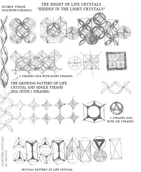
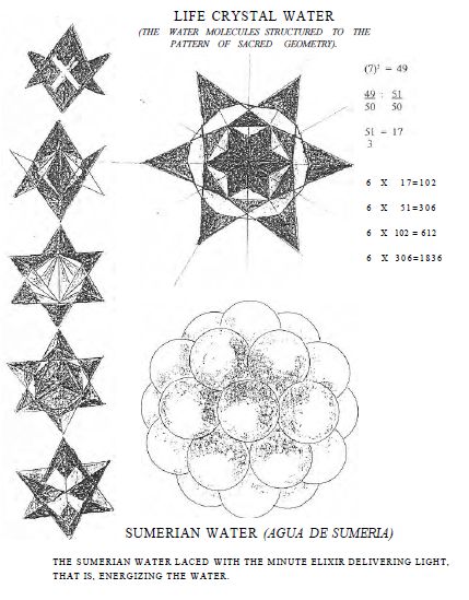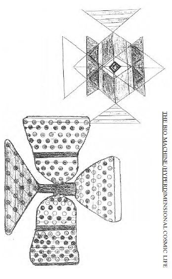
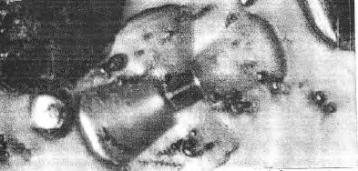
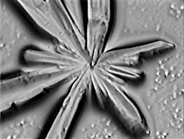
**BioCosmic Machine ... Life Crystals**
---
[**http://sun-nation.org/**](http://sun-nation.org/)
---
**NOTE : Due to bandwidth issues, the complete
illustrated 38 MB PDF of this book no longer is posted here,
but it is included on the Civilization Kit DVD.
Here is the link for the original online posting @
sun-nation.org :**
**
**
---
**TEXT ONLY :**
**[ Prefatory Text Image Captions ]**
HOME IN ON LIFE!
WHEN ELECTRONS PLACED IN SACRED GEOMETRY, A COHERENT ELECTRON
BEAM IS PROVIDED BY THE SUPERLATTICE. THE COHERENT LIGHT LACED
THROUGH BETWEEN EACH ROW OF THE SUPERLATTICE. THE SUPERLATTICE
ACTING AS A BEAM SPLITTER, RESULTING IN MULTITUDE OF COHERENT
PHOTON BEAMS. ALL WAVE PATTERNS RAE PINNED DOWN IN THE
SUPERLATTICE, REMAINING IN PLACE. PHOTON EMISSION THEN UNDER
CONTROL. THE WAVE ADDITION THEREFORE WILL UP SHIFT THE
AMPLITUDE.
SINCE THE MOLECULES ARE IN LOCK STEP, THE SPLIT BEAMS ON THE
EXIT RESULTING IN A MULTITUDE OF INTERFERENCE PATTERNS,
LOCKING IN THE CAPTIVATED BLUEPRINT OF EXPRESSED GENETIC
MOLECULES. THE CAPTIVE BLUEPRINTS OF LIFE FORMING TEMPLATES IN
LIGHT, THAT WILL SERVE AS THE SKELETON OF LIFE. THE BUILDING
BLOCKS NOW CAN FILL IN THE SACRED MAP OF PHOTONS TO REASSEMBLE
LIFE FROM THE INFORMATION STORED IN LIGHT. BLOCKING IN THE
CONSTANT PHASE, ENSURES THE TEMPLATE PRINTING OF INTERFERENCE,
THE MOBILITY OF THE MOLECULES HELD IN ORDER BY THE
SUPERLATTICE.
EXTERNAL LIGHT WILL LACE THROUGH THE ORDERED STRUCTURE,
ORDERED INTO COHERENCE. IF THIS SYSTEM IS TRANSPLANTED INTO
NUCLEOTIDES OF GENETIC MATERIAL, SACRED GEOMETRY WILL FOLLOW.
ONCE THE GENETIC MATERIAL IN SACRED GEOMETRY AT THE
INTERFERENCE POINTS, GENETIC BLUE PRINT LOCKS IN VIA COHERENT
BEAMS FROM WHICH LIFE REPLICATED.
INBORN THE BLUEPRINT OF LIFE WITH TIME AND SPACE FROM HIS
BREATH, IN BURSTING BUBBLES LIFE HAS BEEN DELIVERED. INSTANT
LIFE FORM IMPLODING THE LIFE CRYSTALS CATALYZED BY CO2. GRAINS
OF LIFE IN SUPER LATTICE, AMINO ACIDS IN LOCK STEP ARE FIRST
PROTEINS NEATLY MOLDS THEN RNA FOLLOWS.
THE GRAINS OF LIFE'S CRYSTALS ARE ALIVE AND DREAMS USHERED BY
THAT OF MYSTERIOUS HANDS, GENETIC CRYSTALS RESPOND AND ARE NO
LONGER A DREAM.
(IMPLODING LIFE CRYSTAL IN A CO2 CATALYZED MEMBRANE FIRST
AMINO ACID FORMS THEN PROTEIN AND FINALLY RNA AND MICRO
ORGANISM.)
SUPER MATRIX OF POLY ADENOSINE NUCLEOTIDE PHOSPHATE IS THE
ELECTRON TRANSPORT TO CONVERT CO, TO ORGANIC MOLECULES.
THIS SUPER MATRIX DELIVERS ENERGY TO PRODUCE ATP DRIVEN BY
PROTON GRADIENTS AND SPLITTING WATER BY
ELECTRO-PIROTOSYNTHETIC PROCESS.
THIS MECHANISM DRIVES THE COSMIC INCUBATOR THAT PROBABLY
EXISTED AT THE TIME LIFE EVOLVED. THIS INCUBATORS CAN PROCESS
LIFE BUT ALSO ARE A VERY EFFICIENT ATP SYNTHESIZER. THE COSMIC
INCUBATOR CAN PROCESS CELLULOSE-ALDEMYDES AS WELL AS CO2 INTO
GLUCOSE AND ATP.
THE OWNER OF CROSS AND THE STAR OF DAVID REPRESENT THE COSMOS.
EVEN IN LIVING CELLS AND ORGANISMS, YOU FIND THE STAR OF DAVID
AND THE SUPERLATTICE OF PROTEINS OR NUCLEOTIDES AS THE CREATOR
PLACED IT. THE SUPERLATTICE FOLLOWS THE ELECTRON CONFIGURATION
IN LOCKSTEPS. FIRST CRYSTALS, AND LIGHT SYNTHESIZED CARBON
DIOXIDE, THEN CAME THE PRECURSORS OF THE MITOCHONDRIA, THE
COSMIC INCUBATOR.
POLY NUCLEOTIDES FOLLOWS THE SACRED GEOMETRY THAT IS THE
SIGNATURE OF THE COSMOS. MOLECULES (EC) LINE UP IN LOCKSTEP
(SUPERLATTICE) TO FORM LIVE CRYSTALS, SUCH CRYSTALS ARE STORED
IN THE MITOCHONDRIA-CELL-NUCLEUS-CENTRIOLES AND THROUGHOUT IN
THE CELL, TO STORE ENERGY AND NUTRIENTS FOR THE GENETIC
PROCESS.
When six wave combine with the seventh in the center, the
center one becomes the nuclear well adding all the
waves-crests and their amplitude increases. Slurping them in
like whiteholes, however if the waves are out of phase they
will annihilate (cancel) each other When light is laced
through the rows of electrons or protons ordered in
cosmic-geometry the photons too form superlattice and
countless photon beams. The electrons in superlattice act as a
beam splitter. The coherent waves emerging from such system
will form interference with each other in an orderly fashion.
But since in the crystals electrons, 41 photons and proteins
are also in superlattice they too can form interference in an
orderly fashion. If the square of the wave function of 6 + 1
waves in the superlattice would result in 49 or 42 + 7 that
would manifest in Sacred Geometry. Since we are absorbing
energy in three dimensions, each set of scrolls must be
absorbed at
the same frequency therefore 33 x G = 18-1 the one in the
center becomes the nuclear well absorbing 17 waves this three
dimensional scroll will pair, absorbing a total of 34 waves.
This single scroll (17W) in three dimension (3X17 = 51) forms
one tetrahedral that is equal to one photon. But two
tetrahedral and two photon forming pairs with opposite spin
would be equal to 1 oz. or 51 pair.
The interference field hold the blueprint of life. The
biological process assembles the genetic materials to fit the
skeleton of the interference field of all organism. This field
leads the physical matter of mold of our structure. The field
of life consist of a Hologram of interference that is linked
with the physical structure via the essence of life.
The pillars of the Sacred (Cosmic) Geometry are the six plus
one interference formed from the breath of creation, which
then proliferates throughout the universe and condensed into
scrolls of light particles and matter. The Sumerian elixir is
the Cosmic essence that now has been rediscovered. This elixir
is the cement of life. When protein is brought in contact with
this elixir it will fold into the Cosmic Geometry. This
geometry is then responsible to superconductivity superfluity
opening the way to harness the cosmos. This Cosmic system than
brings organization and continuity to life. The secret to
immortality lies in this Sacred Cosmic order that delivers the
wholeness to every living organism. As, earlier explained, the
scrolls Vortex fields generated by the seven folds
interference giving rise to 3 D oscillation, the prime mover
of the Cosmos, the creative field that condensed into matter
and distilled life itself, via the state of coherence,
developing the interference. When the interference is put
through cosmic order, matter will assume new entropy and the
seventh fold interference represent the scrolls the seed of
light that is molded from the dark (gravity). We shall see how
genetic matter absorbs the elixir that delivers the cosmic
light.
The Cosmos contains Pristine dark matter. This dark matter
represents 90% of the Cosmos. Dark matter is pure and exist in
the form of superlattice. That means that they are coherent
superconductive and superfluid.
Their primary function is to reverse the big bang. They act as
a nuclear well recycling light to generate anti-gravitational
field, countering the gravitational forces of the fields
Cosmos. This matter is translucent but because it generates
anti-gravitational field, that traps light, such a matter is
dark. This gravitational field is compressing the light,
imploding and forming dirty matter that becomes suns and
stars. This dirty matter with chaotic interference heads
towards aging -then recycle.
The anti-gravitational forces are countering the forces of the
big bank, therefore acting as a break and slowing all motion
in the Cosmos. The distance of the heavenly bodies therefore
will not reflect the age of the Cosmos. Photon belts are
captive of anti-gravitational forces and black matter. Such
forces can disturb (interrupt) gravitational forces within a
solar system causing catastrophic events, even pole shift of
planets. In such an event there is complete darkness caused by
the anti-gravitational fields capturing the light.
Many believe that there is a twelfth planet with an orbital
time of 36 thousand years. If such a planet exists it must be
composed of Cosmic transparent matter. That would make the
planet black, but also churning out anti-gravitational field
powerful enough to breakout from the solar gravitational
field. It probably orbits between two suns which would explain
the long orbital path. The composition would also explain the
catastrophic events on earth, when this planet passed by,
disturbing the solar system by gravitational field
interaction. The interference patterns between suns and its
planets, if disrupted, would result in orbital changes. Such a
catastrophic event could bring about airborne seas and matter,
causing planets to flip over or even collide. Historical
evidence indicates that such event took place in Biblical
time.
We know from historical evidence that the Sumerians appeared
in the Mesopotamian Valley about seven thousand years ago,
setting up four colonies. The Semitic genes, received from my
mother, shall now re-explore, to bring back the Sumerian past
they left behind as they inbred with the Semites before they
vanished. One question remains unanswered: Did they leave as
giants or perhaps they miniaturized themselves and stayed?
They certainly had the knowledge to do it.
Before, I present my documentary to you, I have to take you
back to the beginning of time.
The universe must be in equilibrium. Therefore, it must
contain two opposing forces, a positive and a negative force.
A forward force and a reverse force. At the beginning of time
forces were released from an energy well we call the big bang.
This free energy generated the gravitational time, - space -
and the blueprint of the cosmos was thus born from the breath
of creation.
The six plus one (the sevenfold) gravitational wave is the
pillar of the Cosmos, The one gravitational wave became a new
energy well absorbing the other six, braiding the wave fronts
along the
interference, becoming a unit, then seven units forming a new
unit, and the energy being compressed into matter. The new
matter is Virgin (Pristine) matter, as the interference of the
energy waves
remains orderly in sacred geometry, this (Sacred) Cosmic
matter which some call dark matter, in reality is transparent
matter, which can form black holes turning out
anti-gravitational field and recycling matter.
The opposing implosive force of explosion, is countering the
forces of the big bang. When time retreats, aging shall
reverse. Invisible matter interference is chaotic matter in
the galaxies suns and stars, turning out trash as aged matter
is on its way towards recycling via imploding red
giants-neutron stars and blackholes.
The Sumerians taught us cosmic geometry and cosmic math. The
restoration of Sumerian math is still in my genes-"THE PAST"
**COSMIC MATTER MOSTLY PRISTINE**
In Pristine matter, the interference points are organized and
is in lockstep forming superlattice. Such a Pristine matter
hold the breath of creation and the blueprint of life itself
Since Cosmic Pristine matter is in superlattice, it therefore,
is superconductive; further such superlattice can form an
infinite variation of Cosmic life that is far superior to us;
since it is energy rich it can process CO2 and water in the
presence of air, glucose and genetic components. Also the
elixir of life is produced, elixir that promotes life and
cosmic geometry. The cosmic black protein is the precursor of
the mitochondria that in turn replicates the cosmiana which
then becomes the precursor of the Chondriana, and the
Chondriana is the precursor of the Mammalian life forms.
But this Cosmic Pristine matter is replicating plant life that
turns out Sacred proteins and the elixir of life. Pristine
Cosmic matter is the foundation of a Cosmic Physics unknown to
us until now. Since the backbone of the cosmic matter is
Sacred Geometry produced by orderly interference of energy
waves, it is capable of storing the breath of creation with
the blueprint of life. Therefore relocating the predestined
life forms. Such life forms has been discovered, call them the
Cosmic incubators.
**COSMIC INCUBATORS ARE HYPER-INTELLIGENT**
Cosmic life forms are erecting hardware and assembling them
into Bionic Plants. The life forms are capable processing
software to replicate life from interference of waves (light)
that molds the breath of creation. The Elixir they produce is
being used to deliver the Life Energy and the Cosmic order.
The Sumerians tried to tell us this incredible Cosmic order,
translating it into a primitive language that now has been
translated into our own primitive conception.
Proteins Scientist with gender design and build Biomachines,
following the Cosmic order. These Cosmic life factories and
their scientist came here. The question is when did they
land?, or were they here all this time, or did I call them
back via Cosmic Science? Or perhaps the Sumerians never left,
they just miniaturized themselves. I have documented and
actually miniaturized and magnified life forms via
interference Cosmic order. It is like a "Hyper-dimensional
Hologram". Imaging a flying saucer or spaceship that turns
into microscopic size and hides in a grain of sand, or
crystal. Smart proteins hold the blueprint to all life forms
including the Biomachines. Ordinary protein hold the
Biostructure. Smart proteins hold the blueprints in
interference or perhaps seek out and process information held
captive in the interference pattern. Proteins Scientists are
bom out of the Elixir of Life that delivers the Cosmic Order.
These Cosmic Scientists are harnessing the Cosmic order that
holds the breath of creation. The arrival of this new
Macro-Science is the beginning of a New Age, as we will be
able to enter into the higher Cosmic plane. One of the
criteria is the Sumerian water that is structured to Cosmic
order. By altering the hydrophobic and hydrophilic properties,
such water is essential to all life and is found in the
nucleus of a cell in the central to build microtubules
(spindles for cell division) in the mitochondria where the
protein substrate that processes ATP is in Sacred water.
(Cosmic Geometry and is superconductive such water is also
found in the cerebral spinal fluid where the nerve impulses
are transferred to the distribution points). (These are
fingerprints of the Cosmos.) The Sumerian elixir plays an
important role to processing such water and produce to
specific geometry. Parts of Beta sheets in Cosmic order made
from large proteins. They also design the amino acids to the
desired length. They design and build protein riveting
machines to build intricate Biostructures. They design and
build phasing in or out dish antennae fields, with bell shaped
optical devices to produce interference blueprints.
All this protein precision hardware is hooked into a specific
life replicating engine that then processes the information to
replicate life genetic material from light (holograms) holding
the blueprint.
They are building and stacking the Beta sheets of proteins by
assembly workers laying down the proteins one by one like the
masons laying down bricks.
They fit the peptides into three, dimensional geometry by
instant production like bees building honeycombs. Again they
use Sacred water as a scaffold, acting as a mold, in
conjunction with the interference pattern laid into the Cosmic
Geometry.
These Cosmic scientists have arrived and have been
domesticated to teach us the Science of the Cosmos, as the
Sumerians had access to it, with the discovery of Life
Crystals I was able to mass produce layered stacked protein
beta sheets to produce crystals in Cosmic order. These
crystals then are able to self hologram and reproduce
themselves by copying via hologram. This paved the way to the
Sumerian technology which they brought with them when they
landed in the Mesopotamian Valley seven thousand years ago.
Now the Sumerian literature they left behind has been
translated and the Sumerian math and geometry have been
restored to understand the Cosmos and how energy is condensed
into matter.
The Life process is self controlling once we provide the
elixir of life. The Elixir the Sumerians had, has been
re-discovered. "Now that I know of what I know, I realize how
little we all know."
**ATOMIC SELF REPLICATION VIA HOLOGRAM**
6+1. As energy braids to form tetrahedral, Cosmic Geometry
condenses matter from Gravitron-Scrolls and light components
of matter within the microcosm are in Sacred Geometry. Sacred
(Cosmic) Geometry exists in ordered interference
patterns that hold the blueprint of the breath of creation. It
is a self replicating system via interference hyperdimensional
hologram. Throughout the universe matter is alive, replicates
ages via star systems, then recycles through BLACKHOLES.
In Nuclear well energy, gravitational waves are compressed
into matter; in a black hole, matter is decomposed into
gravitational waves.
In a cell Nucleus, genetic material replicates via self
hologram in water structured to Sacred geometry. ATP is
produced in the Mitochondria, where the protein substrate is
in Sacred geometry. The whole Cosmos is alive, but when the
Cosmic order is disturbed, death will follow.
In Sacred Geometry the interference pattern holds the key to
self recognition and replication. If the hologram is in
positive focus and magnified, the replication pattern commands
giants, but if the
interference pattern is de-magnified, the replication pattern
commands miniatures. The size of the whole Cosmos is relative,
that includes optical illusion and mirages. The interference
points (Patterns) are viable, therefore sizes can be
controlled by positive of negative forces, giving rise to
birth or replication or death to annihilate. The sizes fall in
between: implosive forces form the macrocosm, explosive forces
creates Microsm.
With the volume reduction of energy, mass number will
increase. But with the expansion of space energy liberated
from mass, compression and decompression is the name of the
game. In order to create a nuclear well to condense energy
into matter all gravitational waves (6+1) must be placed in
Cosmic order, in your language in coherent phase. This radiant
energy then forms an interference pattern of six in 360
degrees and draws into the center one that becomes the nuclear
well, creating an implosion well opposite to the force
released by explosion from positive monopolies. Actually, we
can say that a nuclear well is six wave; interaction is drawn
into the seventh forming wave units to form a graviton energy
unit. Now when we take seven gravitron or Gravity Waves in the
same way, we form phase coherence to fill the nuclear well to
braid to scrolls. Finally, a photon and quantum of light has
been born. Now, when we begin to assemble quantum of light in
marching phase. Sacred Geometry forms and transfer
electrons-photons-proteins into Cosmic form, superconductivity
and superfluity will commence.
Now, when we adopt the Cosmic physics to smart proteins or
genetic grains, we can replicate Bio computers surpassing the
brain function: self-replicating, self-restoring,
self-maintaining and alive to serve us and to be our friend. A
new family of scientist production and assembly workers are
already here; they could be put into service to revolutionize
our industry. The potential is hard to comprehend even for me.
They could recycle the excess CO2, savings us from the
greenhouse effect and turning it into clean natural food
(glucose-ATP); They could build industry, eliminate all
diseases and regrow limbs and organs. But most of all, they
would give us those extra years for space travel. The new
Bioelectronic industry would tap the Cosmos for free energy
for the world. Via superconductivity-superfluidity-photo
synthesis and tap into the Atom without a nuclear reaction.
The new institutions shall free the minds from captivity,
encouraging us to dream, explore, and use our intuition. This
is the reality today as the New Age shall sweep out the old
one once and for all.
This is not the realm of science fiction, but the facts that
my guys are here to prove . See it yourself .
There are several ways to enter into an Atom. But the ideal
way is with low energy photons or particles in Cosmic
Geometry. By absorbing a high energy photon to deliver quantum
of energy. A single photon has to be at a high energy level to
create the tunnel through the interference gates. In adopting
the Cosmic Geometry, three photons at one third energy level
accomplish the same result. One must realize that there are
smaller energy units than photons and quantum of energy can be
delivered in smaller multiple units such as scrolls and
gravitons. Gravitational wells have implosion pull and the
receptance of the Cosmic order is a delivery highway system.
Energy can be pulled out of the Cosmos by implosion and can be
delivered via Sacred Geometry where free flow of energy takes
place.
In ordinary matter, when the delivery system breaks down, the
interference is chaotic (Road Blocks). In the Cosmic Geometry
the interference of all waves is in an orderly system,
creating a front where all the energy is like raindrops
forming a river of flow. Note that the Biomachine has two
phase in and phase out Vortex dishes, one to decrease or
cancel the wave front (Black, which the white Vortex dish is
to add or amplify the amplitude of waves).
Both dishes are coupled with the reproduction chambers where
the reproduction of proteins takes place via interference,
copying with the aid of the two bell shaped optical devices.
The energy is transferred to the molecular bond and is also
used for the photosynthesis of CO, to make glucose utilizing
the protein substrate in Cosmic Geometry.
In case of (6+1) wave interference, the result is producing a
new wave intensity of (6+P= 49
Cosmic Wave Amplitude (6+1) = 7
(6+1)+ (6^+ V-) + 2. (6)(1)= 49 + 51
2 waves used as nuclear wells 2x7=14 + (6 + l) = 37+I4 = 5)
2X 50+ 1 =49 + 51
Biomachines are high energy Cosmic life forms. Their energy
requirements are high. Once the Biomachines are completed,
they cover themselves with protein substrates in superlattice.
Via this superlattice protein substrate, they get free energy
transfer to satisfy their needs.
All space between parts and sandwich substrate are insulated
with dielectric nucleotide crystals which also serve as part
of the optical system to project holograms.
To drain energy from the nucleus we must shift the waves out
of phase so that wave "x" is positive and wave "y" is
negative. The reduction of amplitudes and intensity will be
determined by the phase shift. If x = y, the opposite
direction interference will disengage and gravitational waves
are turned loose generating a gravity field. This is achieved
by a superlattice Vortex reversing the spin state of the
waves.
The Cosmic Biomachine has two such Vortex dishes to control
positive and negative interference and to control the Cosmic
hyperdimentional hologram. The white dish produces the
constructive interference and the black dish produces the
destructive interference.
In other words, the black dish produces gravitational waves
which capture the light, and unhilating and disassembling it,
while the white dish produces the coherent beams for
hyper-dimensional interference.
All this is coordinated with the optica! system. Also controls
the viable intensity of the wave form interfering.
The incubator adjusts the maximinima control of interference
intensities for desired functions, phasing in and out the
coherent flow of wave fronts. (This can also explain the
scrambling of optical focus on the microscope).
**THE POWER CROSS**
QUARK E-E + 2 QUARKS = PROTON = 18 3 5 ELECTRON QUARK ROTATION
DETERMINE THE SPIN OF PROTON THEREFORE SETS THE ORTO OR PARA
POSITION.
IN MERKLS DIAMOND SOME CARBON IN THE DIAMOND LATTICE REPLACED
WITH NITROGEN TO GIVE LUSTER TO THE DIAMOND. CREATING
PARAMAGNETIC CENTERS THAT ACT AS AN ENERGY TRANSDUCER AS THE
LIGHTER CARBON OSCILLATES AROUND THE HEAVIER NITROGEN, WHEN
THE NITROGEN TRANSFERS ENERGY TO THE CARBON SUCH PARAMAGNETIC
CENTERS ARE REVERSING THE SPIN OF THE PROTON BECOMING PARA
PROTON (HYDROGEN IN NATURE ARE TWO ORTHOS POSITIONED AND ONE
PARA POSITIONED.) VORTEX FIELDS PRODUCING GRAVITATIONAL FIELDS
BECOMING SUPER GAS AND SUPER FLUIDS. SUCH AS (Nb, CU HYBRID)
(SIH2 Sh) SILICON SULPHUR HYBRIDS ETC. NOW ATP PROVIDES Ht
PROTONIC HYDROGEN IN HYDROLIZATION IN BREAKING DOWN TO ADP.
(+P + Ht) LIFE CRYSTALS DEPOLARIZING WATER WHEN SATURATED.
SUCH DEPOLARIZED LIQUID WHEN RAISED TO HIGH TEMPERATURE THEN
ATOMIZED TO COOL IT INSTANTLY REVERSES HYDROLIZATION, THE
GRAVITATIONAL FIELD PRODUCED BY THE PROTONS COMPRESSING THE
ATP MOLECULES CAUSING IMPLOSION PRODUCING MONOPOLS VIA VORTEX
FIELD EXTRACTING FREE ENERGY BY IMPLOSION. IN OUR GALAXY WHEN
GRAVITATIONAL WAVES (FIELDS) COMPRESS PHOTONS - PLASMA AND
GASES WILL FORM WHICH THEN COMPRESSED BY SUDDEN COOLING UNDER
GRAVITATIONAL FIELDS TURNING OUT SUNS AND STARS.
NOW IF ADENOSINE PHOSPHATES, GUANOSINE PHOSPHATES AND FIVE
CARBON SUGARS ARE SUBJECTED TO SUDDEN COOLING FROM HIGH
TEMPERATURE UNDER GRAVITATIONAL FIELD PRESSURE IT WILL RESULT
IN THE FORMATION OF NUCLEOTIDES-NUCLEOSIDES INTO FRAGMENTED
GENETIC MATERIAL. HOWEVER LIFE AS WE KNOW WILL FORM ONLY
ACCORDING TO THE BLUEPRINT THAT IS HELD CAPTIVE IN THE BREATH
OF CREATION PREDESTINED! WHEN THE UNIVERSE WAS FORMED FROM THE
BREATH OF CREATION (BIG BANG) THE ENERGY COMPRESSED IN THE
MONOPOLES HAS BEEN RELEASED INSTANTLY TWO THIRDS OF OUR
UNIVERSE WAS FORMED IN A FRACTION OF A SECOND, AS THE ENERGY
LEANS FROM THE GRAVITATIONAL FLOW THE VORTEX FIELD BEGINS TO
BE INDUCED COLLAPSING THROUGH THEIR CENTER AND BEGAN TO
OSCILLATE AND SPIN FORMING SCROLLS; THE SEEDS OF LIGHT. THIS
IS HOW LIGHT AND MATTER EVOLVED. BUT, AT THAT INSTANT OF
CREATION SOMETHING ELSE HAPPENED, THE FORCE OF LIFE WAS BORN.
INBORN WITHIN THE BLUEPRINT OF LIFE, WE WERE IN EXISTENCE IN
THE FORM OF HIS BREATH BEFORE THE COSMOS WAS FORMED. A
MONOPOLE BORN OUT OF A VORTEX FIELD THAT DRAWS FREE ENERGY
FROM THE COSMOS. THROUGH THE BIG BANG EXPLOSION ENERGY
RELEASED AND EXPANDED; TO GET SOME OF THIS ENERGY WE HAVE TO
CREATE IMPLOSION, WHICH IS FEASIBLE BY A COMPRESSED
GRAVITATIONAL FIELD.
THIS IS THE WAY STARS DRAW ENERGY FROM THE COSMOS. PARA HYBRID
IS THE KEY. TWO MONOPOLES FORMS A DIE-POLE. THE SPINS
DISTORTED FORMING NORTH AND SOUTH POLES CENTERING MAGNETIC
FIELD BUT A NINETY DEGREE TO THE MAGNETIC FIELD GRAVITATIONAL
FIELDS ARE RADIATED. THE MAGNETIC FIELD SETS THE PATTERN OF
CRYSTAL GROWTH, BUT IF THESE CRYSTALS ARE PARAHYBRIDS THE
VORTEX FIELD WILL TAP INTO THE GRAVITATIONAL FIELD TO FORM
MONOPOLES NINETY DEGREES TO THE MAGNETIC IMPRINT. NOW IF FOUR
MONOPOLES MATCHED ACCORDINGLY NINETY DEGREES APART, THE POWER
OF CROSS WILL FORM, CREATING A QUARAPOLE. THE MAGNETIC IMPRINT
NOW APPEARS AT FORTY FIVE DEGREES BETWEEN VORTEX FIELDS. SUCH
SYSTEM TAPS INTO THE COSMOS FOR FREE ENERGY, GENERATING
ANTI-GRAVITY AND FORMING "THE POWER OF THE CROSS". THE POWER
OF THE CROSS FORMING THE BLACK SUN, WHICH IS COMPRESSED
GRAVITATIONAL WAVES DERIVED FROM RADIANT ENERGY; ACTUALLY
BREAKING DOWN THE WAVE LENGTH CONVERTING IT TO GRAVITATIONAL
FIELD.
"BLACK SUN RADIATES INWARD REMAINING DARK" (A QUOTATION FROM
JOURNEY IN COMMA 1985)
A VORTEX FIELD RENDERS RADIATION HARMLESS (AS IT DESTROYS IT)
IT BREAKS DOWN ANY WAVE LENGTH INCLUDING MICROWAVE OR RADAR
THIS IS WHY THE DELTA WING IS BLACK (SEE VIDEO DOCUMENTARY)
SUCH VORTEX FIELD THEORETICALLY IS CAPABLE TO RENDER HARMLESS
ALL NUCLEAR WEAPONS BUT AT THE SAME TIME LEVITATE AND POWER
FLYING SAUCERS AND FREE THE HUMAN RACE AT LAST.
POSITRONS AND ELECTRONS 0RGANIZE IN A LOCK STEP TO FORM SUPER
LATTICE AS THEIR SPIN RESONANCE INTERLOCK.
SUCH A SYSTEM HAS SUPER FLUIDS AND SUPER CONDUCTIVE
PROPERTIES. SUPER FLUID DISOLVES ELECTRONS AS ELECTRONS
DISSOLVES PHOTONS, BY PAIRING SUCH PHOTONS AND ELECTRONS AN
ORDERED MATRIX FORMS. PROTONS WITH POSITIVE CHARGE ALSO
CAPABLE TO FORM SUPER LATTICE AS THEIR SPIN RESONANCE
INTERLOCK.
WHEN SUCH STATE SUPERIMPOSED ON THE DNA A MULTI-STRAND SUPER
DNA MAY FORM MOLDING (COILING) INTO CONDENSED GENETIC MATERIAL
CRYSTALIZING INTO INTELLIGENT LIVE CRYSTALS. SUCH CRYSTALS ARE
CAPABLE TO TRANSFORM EITHER POSITIVE OR NEGATIVE ENERGY TO
MOLD OR RECYCLE.
THESE CRYSTALS CAN ABSORB AND HOLD AN ENORMOUS AMOUNT OF
ENERGY LIKE STORAGE BATTERIES. SINCE THE ENERGY ORIGINATES
FROM THE SPINS, THE CURRENT WILL OSCILLATE. THIS SELF
DISCIPLINED CRYSTALS HAVE INTELLIGENCE THEREFORE RESPONDS IN
TANDEM TO SUPPORT OR FORM LIFE BY TAPING INTO THE COSMOS FOR
THE BREATH OF CREATION.
THE TWO INTERACTING SPIN OF AN ELECTRON OF PROTON WILL
INTERLOCK A THIRD PARTICLE SPIN AND BEGIN THE FORMATION (LIKE
A MILITARY) FORMING SUPER LATTICE. MULTIPLE INTERACTIONS
FORMING LARGER GEOMETRICAL SHAPES LIKE QUADRAPOLES AND
OCTAPOLES OR EVEN HEXAPOLES. THESE INTERACTIONS ARE
RESPONSIBLE FOR THE SUPER CONDUCTIVE OR SUPER FLUID PROPERTIES
THAT ARE REQUIRED TO FORM THE MONOPOLES EITHER LIQUID OR
SOLID. THE POSITIVE INTERACTION
IS RESPONSIBLE FOR THE LIGHT POLARIZATION OR GRAVITATIONAL
WAVE GENERATION. THE NEGATIVE INTERACTION RESPONSIBLE FOR THE
ELECTROMAGNETIC FIELD GENERATION. WHEN SUCH CRYSTALS COME
ALIVE THE GRAVITATIONAL FIELD IS LIFE FORCE. INTELLIGENTLY
DIRECTING THE (LIFE) GROWTH PROCESS, THE RADIANT ENERGY
INTERACTS WITH THE MAGNETIC FIELD TO EXTEND TO EXTEND LIFE AND
REPLICATE.
THE MAGNETIC MOMENT CONTRIBUTED BY THE ELECTRON SPIN, AND THE
OPPOSITE SPINS SEEK OUT EACH OTHER TO PAIR; FORMING THE SUPER
LATTICE. THE PROTONS PAIR AS ORTHO TO PARA SPIN OR AS TWO
ORTHO TO ONE PARA. (PURE PARA IS THE MOST PREFERABLE FOR
FORMING SUPER GAS FOR IMPLOSION). THE PAIRED PROTON SPIN
RESONANCE RESPONSIBLE FOR THE GRAVITATIONAL FIELD. SUCH
GRAVITATIONAL FIELD IS ESSENTIAL FOR THE IMPLOSION GENERATING
THE NEGATIVE FORCE SQUEEZING THE LIGHT (PHOTONS). NOW, DURING
IMPLOSION THE ATP-GTP AND THE FIVE CARBON SUGARS ASSEMBLE INTO
A LONG DNA MOLECULE CHAIN. THE ELECTRONS ARE USHERED ALONG THE
DNA WHICH IS FORCED TO PAIR FORMING A SUPER CONDUCTIVE STATE.
THE PROTON POLARIZES THE LIGHT AND GENERATES GRAVITATIONAL
FIELD VIA VORTEX, TRIGGERING THE IMPLOSION AND INSTANTLY
CONDENSING LIFE FORMS, INCLUDING MONOPOLES. THE DNA GOES
THROUGH A PHASE TRANSACTION DURING IMPLOSION THE (DISPERSED
DNA ATOMIZED AND COOLED INSTANTLY FROM HIGH TEMPERATURE) SPIN
INTERACTION WAVES FORM WHEN THE DNA NUCLEOTIDES, CROSSING THE
PHASE TRANSITION TEMPERATURE. GRAVITATIONAL WAVES CAPTIVATING
PHOTONS CAN SUPER IMPOSE A SPIN WAVE INTERACTION ON THE DNA
FORMING SUPER LATTICE DNA THAT YIELDS LIFE UPON IMPLOSION.
LIFE THAT HAS NOT, UNTIL NOW HAS BEEN KNOWN BY MAN ON THIS
PLANET. IN A CONTINUING PROCESS ON THE GALAXIES AND ON OUR
MILKY WAY GRAVITATIONAL WAVES COMPRESSING AND IMPLODING VIRGIN
MATTER TO FORM SUNS AND STARS.
BY IMPLODING ADENOSINE - GUANOSINE PHOSPHATES AND FIVE CARBON
SUGARS IN A BUBBLE WITH CO2 CATALYST, INSTANT LIFE FORMS.
FIRST AMINO ACIDS, THEN PROTEINS THEREAFTER RNA. THIS
CONTINUING PROCESS IS MIRRORING THE UNIVERSAL PROCESS.
ELECTRONS CAN BE USHERED ALONG THE LONG CHAIN OF THE DNA
MOLECULE WHICH ARE THEN PAIRED AND ARRANGED IN LOCK STEP SO
THAT THE AMINO ACIDS AND PROTEINS CAN CRYSTALLIZE IN SUPER
LATTICE IN LOCK STEP TO FORM INTELLIGENT LIVE CRYSTALS.
IN A TRANSFORMER THE CORE GENERATES THE FIELD THAT ARE
INDUCING THE CURRENT IN THE COPPER COIL WOUND AROUND THE CORE.
THE DNA IS THE LIBRARY OF THE PAST HOLDING THE INFORMATION FOR
THE GENETIC PROCESS.
THE DNA CAN NOT FUNCTION WITHOUT THE LIFE ENERGY CONTRIBUTED
BY THE PROTEIN.
AS THE DNA IS WOUND AROUND THE HISTONE IT COMES ALIVE.
THE BREATH OF CREATION ACTIVATES THE DNA. THE LIFE
PROCESS BEGINS.
LIFE CRYSTALS CONTAINING AMP-ADP-ATP-GMP-GDP-GTP SOME OF THIS
COMPONENT OF LIFE ARE SOMEWHAT TOXIC. BY THEMSELVES
INACTIVATED AS SOME ARE UNSTABLE-INACTTVATED BY SOLVENTS OR
EVSOLUBLE. BUT IN LIFE CRYSTALS THIS BRICKS OF LIFE CEMENTED
WITH FRUCTOSE PHOSPHATES AND GLUCOSE PHOSPHATES. JUST LIKE IN
THE DNA THE SEQUENCED ADENOSINE AND GUANOSINE ARE CEMENTED
WITH SUGAR PHOSHATES.
THIS IS WHY LIFE CRYSTALS ARE TRANSPORTED THROUGH THE CELL
MEMBRANE AND CAPABLE OF NOURISHING THE CELL, AND THIS IS THE
REASON LIFE CRYSTALS HAVE ZERO TOXIC EFFECT, JUST LIKE IN THE
DNA.
REFERENCE **US PATENT NO. 399595** [ ? ] THIS MAGNIFICENT
PIECE OF NEW PHYSICS HAS BEEN EXTENDED BY A FURTHER PATENT
DESCRIBING THE INTRA STELLAR IN ORGANIC POLYMERS **US PATENT
NO. 4029747** (AND TWO OTHERS) THIS TECHNOLOGY HAS BEEN
ADOPTED TO INDUCE COLD FUSION WITHIN ORIENTED LATTICE DOMAINS
CREATING MINIATURE SUNS AND HYDROGEN BOMBS, AS DEMONSTRATED TO
THE D.O.E. IN 1977. THIS AND MANY OF MY OTHER MILESTONE
DISCOVERIES ARE AHEAD OF TIME.
WHILE REALIGNING THE GRAINS OF VERY HIGH PURITY METAL CRYSTALS
AND OPENING UP THE DOMAINS INTO SIMPLE GEOMETRICAL FORMS,
MINIATURE ACCELERATORS ARE CREATED, AND WHEN (PLASMA) IONS ARE
PUMPED THROUGH THE DOMAIN, A DIPOLE OR QUADRUPLE STATIC FIELD
WILL BE SELF INDUCED THAT MAY BE UTILIZED TO OPEN OR CLOSE THE
DOMAIN TO CREATE THE CONDITION TO FUSE.
WHILE THE DOMAIN IS OPEN THE GRAINS ALIGNED WITH THE FLUX LINE
OF THE STATIC FIELD. THIS IS ACHIEVED BY INTER FUSION OF
(POSITIVE HYDROGEN IONS) PROTONS THAT IN TURNS, POLARIZING THE
ELECTRONS REDUCING THEIR MAGNETIC MOMENTS. THE ORIENTED STATIC
FIELDS WILL SPONGE UP THE VORTICES OF FLUX, CAUSING
SCATTERING, ALLOWING FREE FLOW OF CURRENT.
THE PROTON AND ELECTRONS WILL CREATE AN OPPOSITE DIRECTION
FLOW MAINTAINING THE STATIC FIELD IN PLACE THUS SUPER
CONDUCTIVITY MAINTAINED. THE PROTONS WILL MAINTAIN THE HIGH
ENERGY LEVEL. IN CASE OF THE FIRST SYSTEM (1965)
MERCURY-GALLIUM-INDIUM ON HALOGEN IONS CAN BE INTRODUCED. IN
CASE OF THE HALF ISOTOPIC PROCESS WHICH INVOLVES QUADRUPLE
MOMENTS I USED MERCURY IONS AS HEAT TRANSFER MEDIA TO FLUSH
THE HEAT OUT OF THE LATTICE DOMAIN CREATED DURING FUSION. I
INTRODUCED THE MERCURY INTO THE DOMAIN IN HYDRIDE FORM WHERE
THE MERCURY BECAME IONIC GIVING UP ITS HYDROGEN. THE MERCURY
ION CIRCULATED THROUGH THE DOMAIN COOLING THE MATRIX. IF
SCATTERING INTRODUCED VIA IMPURITIES A HOT SPOT DEVELOPED OVER
HEATING THE LATTICE THEREBY EXPANDING AND CLOSING THE DOMAIN.
SUCH HOT SPOTS MAY SPREAD LIKE A DISEASE BY OVERHEATING THE
ADJACENT LATTICES CLOSING DOWN THE DOMAIN THROUGH OUT THE
SYSTEM DEFUNCT CURRENT FLOW (FREE ELECTRON FLOW) IF THE
PROTONS ARE ACCELERATED WITHIN THE DOMAIN CYCLOTRON IT MAY
INITIATE INTRANUCLEAR REACTIONS. WE MAY CALL THIS INDUCED
NUCLEAR REACTION.
BY POLARIZING THE ELECTRONS AND RENDERING THEM ATTRACTIVE
INSTEAD OF REPULSIVE (VIA SPIN INTERACTION) THE PROTON SMALL
TUNNEL THROUGH THE CHARGE BARRIER INTO THE NUCLEAR WELL
INSTEAD OF CLIMBING MOUNT EVEREST TO REACH THE NUCLEAR WELL.
IN THE THIRD COLD FUSION PROCESS I USE PURE PARA HYDROGEN FOR
INTERFUSION AND SETTING UP CASCADING RESONANCE IN THE
MULTI-LAYERED INDUCED CONDENSER INTEGRATOR.
ALL THIS MILESTONES IN THE (NEW) CONTEMPORARY PHYSICS LED ME
TO LIFE CRYSTAL THAT GROWN IN DEPOLARIZED WATER THAT WAS
CAPABLE OF STATIC FIELD OF FLUX SPLITTING THE GROWTH OF SUCH
CRYSTALS FOLLOW THE PATTERN OF THE FLUX FINGER PRINT.
ONCE THE DOMAIN IS OPENED AND ORGANIZED INTO SIMPLE
GEOMETRICAL FORM AFTER SPIN POLARIZATION BY THE PROTONS THE
PAIRED ELECTRONS ENTER INTO THE DOMAIN AND THE RAPID FLOW
(ACCELERATION OF CURRENT) COMMENCES. THIS WILL THEN FURTHER
INCREASE THE STATIC FIELD, AND THE ANGLE OF THE FLUX WILL BE
PROPORTIONAL TO THE FLOW RATE. THAT CAN BE STIMULATED OR
CONTROLLED BY THE ATOMIC HYDROGEN DIFFUSION RATE THAT IS
TEMPERATURE DEPENDENT. A VERY SMALL POTENTIAL DIFFERENCE
INITIATED BY THE CONDENSER EFFECT DERIVED FROM THE STATIC
FIELD, A HUGE RIVER OF PAIRED ELECTRONS IS BEING DRIVEN BY A
SMALL VOLTAGE. THE CURRENT IS NOT PROPORTIONAL TO THE
POTENTIAL DIFFERENCE, LIKE IN ORDINARY METALS.
"THIS ACTIVATED METALS DEVIATE FROM OHM'S LAW" AS THE GRAIN OF
THE SUBJECT METAL IS REALIGNED INTO SIMPLE GEOMETRICAL STATE
VORTEX TOROIDAL FIELDS GENERATED THAT CAN BE MONOPOLE-DIPOLE
OR QUADRUPLE, IN THE CASE OF BLACK SUN IT IS ALWAYS QUADRUPLE
IF THE DIFFUSION OF (H+ + e- ) ATOMIC HYDROGEN TAKES PLACE AT
EAST AND WEST POLES THAN NORTH AND SOUTH POLES BECOMES THE
ELECTRON AND PROTON SOURCE.
THE MAGNETIC MOMENTS OF THE ALIGNED GRAINS OF THE ALUMINUM
COUPLES SIMULATING FERROMAGNETIC PROPERTIES, THE ATOMS ARE
LINE UP IN CHAINS (LOCKSTEP) THE DEPOLARIZED MAIN STREAM
ELECTRON PAIRS INDUCING VAVE FRONTS ALONG THE FREE FLOW PATH
RESULTING IN SUPERCONDUCTIVE STATE. AS THE SPIN IS POLARIZED
THE ELECTRIC FIELD DIMINISHES THE ELECTRONS BECOMING IDLE AND
PASSING THROUGH THE TRANSITIONAL PHASE THAN PARE ENTERING INTO
A FULLY ORDERED STATE. THE GRAIN MIGRATION WILL LINE UP WITH
THE ANGLE OF THE SELF INDUCED FIELD FORMING ORIENTED SUPPER
LATTICE. (ENCLOSED FOR REFERENCE US PATENT TEACHING THE
IMPORTANCE OF PURITY AND GRAIN SIZES). ONCE THE ALUMINUM
GRAINS GOES THROUGH PHASE TRANSFORMATION IT ACQUIRES A
QUADRUPLE MOMENT OF FOUR CHARACTERISTICS OF THE TRANSITIONAL
METALS.
\* NOTE: THE FIRST SYSTEM IS CONDUCTED AT ROOM TEMPERATURE
USING ALUMINUM METAL WHILE THE SECOND SYSTEM AT ELEVATED
TEMPERATURE, THE FOLLOWING METALS HAVE BEEN USED: GOLD,
SILVER, PLATINUM, PALLADIUM AND OFC COPPER.
IN CHONDRIANA THE DNA AND RNA SEGMENTS ARE THE LIBRARY OF THE
PAST AND PRESENT. HOLDING ALL THE INFORMATION NEEDED FOR THE
BIOLOGICAL PROCESS AND PROLIFERATION.
THE PROTEINS THE DNA WRAPPED AROUND (HISTONES) ARE PROVIDING
THE FUNCTIONAL LIFE FIELDS THAT ACTIVATING THE DNA. ENZYMATIC
FUNCTIONS OF GENETIC AND CHEMICAL PROCESSES CONTROLLED BY THIS
SMART MOLECULES, "PROTEINS".
THE SMART PROTEINS ARE PRODUCED IN THE RECENT CYTOPLASM
LOCATED IN THE HEAD OF THE SPERMATOZOA. THAT IS REPLICATED IN
THE UNDIFFERENTIATED CELLS AND CARRIED OVER TO DIFFERENTIATED
CELLS.
THE PRIMORDIAL SMART PROTEINS SYNTHESIZED IN THE ANCIENT
CYTOPLASM WHOSE DEGENERATED REMNANT RESURRECTED VIA LIFE
CRYSTAL. SUCH TREASURE DISCOVERED IN THE TAIL SECTION OF THE
MAMMAL SPERMATOZOA.
WHEN THE RNA WRAPPED AROUND MODERN PROTEINS IT IS CAPABLE TO
REPRODUCE ALL RECENT GENETIC HARDWARE, REPLICATE AND SELF
INSTRUCT TO CARRY OUT THE LIFE PROCESS. WHILE IF THE RNA
WRAPPED AROUND THE PRIMORDIAL PROTEINS THE INFORMATION PAST ON
TO THE RNA (ACTIVATION) HISTORICAL GENETIC HARDWARE CAN BE
RETRIEVED FROM THE PAST. IN OTHER WORD THE RNA ACT AS AN
ASSEMBLY WORKER FUNCTIONING ACCORDING TO INSTRUCTION OF THE
SMART PROTEIN. IN OTHER WORDS THE RIBOSOME OF THE RNA CARRYING
OUT THE MASSAGE OF ITS PROTEIN IN PROTEIN SYNTHESIS. PROTEINS
AND RNA-DNA ARE INTERDEPENDENT HENCE THE PROTEIN IS THE
ORIGINAL PARENT OF THE RNA-DNA.
THE RNA IS AN INFORMATION LIBRARY AS WELL AS AN ASSEMBLY
WORKER ACTIVATED BY THE SMART PROTEIN THAT PROVIDES THE LIFE
FORCE. AGAIN COMPARE THE RNA-PROTEIN TO THE CORE AND THE
WINDINGS TO INDUCE THE LIFE PROCESS.
THIS LIFE FORCE ENCOURAGE THE BIOLOGICAL MOLECULES TO INTERACT
AND CARRY OUT THE DESIGNATED LIFE PROCESS WITHIN THE CELL.
THIS SMART PROTEIN-RNA COMBINATION NOT ONLY CARRYING OUT THE
LIFE (ENZYMATIC) PROCESSES BUT HAVING THE INTELLIGENCE TO
DISASSEMBLE INVADERS VIRUSES, MICROORGANISM, PROVIDING
INTER-CELLULAR DEFENSE.
THIS PROTEINS FOLDS TO SPECIFIC 3-D GEOMETRICAL SHAPES TO
INITIATE SPECIFIC LIFE REPLICATION. AS THE SMART PROTEINS WITH
THE AMINO ACIDS FOLDS AND SHAPES UNFOLDING THE ORIGINAL LIFE
FORM. (SEE "THE ORIGIN OF LIFE" SERIES).
THE NUCLEOSIDE LIFE CRYSTAL SUPPLEMENTS IN THE LIFE PROCESS
ARE IN THE MONO PHOSPHATE FORM HOWEVER LIFE CRYSTAL CONTAINS
ALL THE OTHER FORMS AS WELL AS THE INTERMEDIATE OF THE
FRUCTOSE AND GLUCOSE PHOSPHATES.
A GENE EXPRESSION OF THE SEQUENCE OF NUCLEOTIDES TRANSCRIBED
TO THE mRNA WHICH ACT AS AN ASSEMBLY WORKER (TEMPLATE) TO
PARTICIPATE IN THE PROTEIN PRODUCTION PROCESS.
SINCE CHONDRIANA IS A SINGLE CELL ORGANISM IT FALLS INTO THE
CATEGORY OF EUKARYOTE. HAVING FOUR RIBOSOMAL CHONDRIANA
SYNTHESIS FROM DISPERSED OR SPLICED GENETIC MATERIALS, THE
UNCODED DNA IS FOLDED INTO CIRCLES WITH THE ACTION OF THE
(GUANOSINE TRI PHOSPHATE) GTP (oH) HYDROXYL GROUPS PLAYING
ACTIVE PART IN THE CLEAVING.
AS THE GTP ACT AS A SPLICING AGENT CLEAVING THE STRAND OF THE
RNA AT THE SITE OF THE FIVE CARBON SUGAR BETWEEN THE PHOSPHATE
GROUP AND THE FIVE CARBON SUGAR - ATTACKING THE
PHOSPHO-DIESTER BOND, THAT IS THE BRIDGE BETWEEN THE PHOSPHATE
GROUP AND THE SUGAR.
ONCE THE DNA IS SPLICED AND FORMS THE RING THE LIFE PROCESS
BEGINS, WITH PROTEIN SYNTHESIS. THE FOUR RNA SEGMENTS HOLDS
THE INFORMATION OF THE HEPLOIDS.
AS THE HEAD OF THE SPERMATOZOA ENTERS THE OVUM THE FIRST STEP
IS THE FORMATION OF THE CHONDRIANA. THAN EVOLVES THE MORULA
CELL CLUSTER (CLEFT APPEARS ON THE MORULA). THIS IS THE CROSS
POINT AS THE PRE EMBRYONIC CELL CLUSTER EVOLVES WITH THE
CHONDRIANA ANCESTOR. FROM THE PRIMORDIAL CELLS THE ECTODERMIC
ENDODERMIC AND MESODERMIC GERMINAL LAYERS, CELL
DIFFERENTIATION BEGINS BY HORMONE ACTIVATION PROVIDED BY THE
OVUM, AS THE EMBRYO COME INTO EXISTENCE. IF THE CHONDRIANA
RECALLED OUTSIDE OF THE OVUM IN THE ABSENCE OF THE HORMONES
THE ANCESTOR CHONDRIANA CAN NOT DEVELOP INTO THE MORULA,
INSTEAD EACH HEPLOID CELLS BECOMES AN INDEPENDENT PRIMORDIAL
LIFE FORMS.
GERMINAL LAYERS IN BOTH THE TESTES AND THE OVARIES PRODUCING
PRIMORDIAL NUCLEUSES THAT CAN TURN OUT CHONDRIANAS IN
CONCEPTION WHEN THE TWO NUCLEUS (THE OVUM AND OF THE
SPERMATOZOA LOCATED IN THE BOTTOM OF THE HEAD) FUSE, DURING
PRE-EMBRYONIC STAGE FIRST THE CHONDRIANA. THE ANCESTORS OF OUR
IMMUNE SYSTEM FORMS IN THE PRE EMBRIONIC MORULA A FUNCTIONAL
MMUNE SYSTEM IS IN PLACE THAT LATER DEVOLVES FROM PRIMORDIAL
IMMUNE SYSTEM TO OUR CURRENT SYSTEM.
ONCE THE IMMUNE SYSTEM IS IN PLACE (PRECURSOR CHONDRIANA) THAN
UNDER THE PROTECTION CELL DIVISION BEGINS THAT LEADS TO FIRST
THE PRE-EMBRIONIC-FETAL TISSUE SECOND VIA HORMONE STIMULATION
CELL DIFFERENTIATION INTO THE FETUS. LIFE CONSIST OF TWO
DIFFERENT ENTITY. THE IMMUNE SYSTEM THAT EVOLVES FIRST THAN
THE HIGHER ORDER OF LIFE THAT MOLDS TOGETHER INTO ONE GENETIC
SYSTEM. THE LINK BETWEEN THE TWO LIFE SYSTEM ARE THE SEX
GLANDS THAT IS CAPABLE TO REPLICATE BOTH SYSTEM.
AS LIFE EVOLVED AROUND THE IMMUNE SYSTEM, THE IMMUNE SYSTEM IS
BEING DEVOLVED (DEGENERATED FROM CHONDRIANA) FOR OUR WELL
BEING THE TWO SYSTEM MUST BE IN BALANCE. TO REVERSE THE
DEGENERATIVE PATH OF THE IMMUNE SYSTEM ONE MUST RESTORE THE
DIMINISHING ENERGY LEVEL. WE EVOLVED VIA DEVOLUTION AS OUR
GENETIC NATION WITHIN OUR CELL UNITED FOR SURVIVAL FORMING AN
ALLIANCE WITH THE IMMUNE SYSTEM.
AT ROOM TEMPERATURE SUSPENDED ANIMATION VIA LIFE CRYSTALS IS
FEASIBLE.
LIFE CRYSTAL PROVIDING LIFE GIVING ENERGY NUTRIENTS AND SAFE
MEDIA FOR PROLONGED SUSPENDED ANIMATION. IF ORGANS OR LIMBS TO
BE PRESERVED IN LIQUID LIFE CRYSTAL SOLUTION THE CHONDRIANAS
SHOULD BE INTRODUCED TO MAINTAIN THE IMMUNE DEFENSE AGAINST
INVADING MICROBES. THE ATP WILL PROVIDE THE ADENOSINE AND
PHOSPHATE REINFORCING THE CELL MEMBRANE, WHILE REDUCING THE
FAT, INTERACTING WITH THE LIPIDS PREVENTING GELLING AT LOW
TEMPERATURE. LIFE CRYSTAL WATER I CALL BLACK WATER WILL
PRESERVE THE DELICATE BALANCE OF CELL STRUCTURE AND ITS
COMPONENTS, INCLUDING THE CALCIUM BLOCKING CHANNELS PREVENTING
THE FLOODING OF THE CELL WITH CALCIUM. THE LIFE CRYSTAL WATER
ALTERED SURFACE TENSION GIVING IT PROPERTIES LIKE LIQUID GASES
SPILLED BREAKING UP TO LITTLE SPHERULES, THEREFORE AT LOW
TEMPERATURE ACQUIRES VITREOUS PROPERTIES AND SLUSH WILL FORM
INSTEAD OF ICE. WHEN THIS SLUSH IS THAWED IT WILL NOT EXERT
THE PHYSICAL PRESSURE, AND WILL NOT CAUSE DAMAGE TO THE
ANIMATED LIFE FORM IN THE LIFE CRYSTAL SYSTEM. SINCE LIFE
CRYSTAL HAS NO TOXIC PROPERTIES IT CAN BE USED SAFELY TO
PRESERVE GENETIC LIFE FORMS. AS THE COOLING ADVANCES FROM THE
OUTSIDE TOWARDS THE INSIDE AND THE CIRCULATION IS SLOWLY
DEFEATED THE FRUCTOSE-GLUCOSE ADENOSINE-GUANOSINE PHOSPHATES
WILL CONCENTRATE IN THE INTERNAL ORGANS. THIS VITAL ORGANS ARE
THE LAST ONE TO WIND DOWN BUT THE FIRST ONE TO THAW AND JUMP
START THE CIRCULATION AS LIFE RESTARTS.
BY CONTROLLING THE LIFE CRYSTAL CONCENTRATION GRADIENT IN
DEPOLARIZING THE WATER AND TEMPERATURE IT IS FEASIBLE TO
MAINTAIN THE BLACK WATER LIQUID INSIDE THE CELL WHILE STOPPING
THE CLOCK ON THE BIOLOGICAL PROCESS. MAINTAINING THE
BIOLOGICAL PROCESS OR STOPPING THE BIOLOGICAL CLOCK (SUSPENDED
ANIMATION FINALLY HAS ARRIVED IN ITS EMBRYONIC FORM).
COLD BLOODED SPECIES CAN REGULATE THEIR REQUIRED ENERGY
PRODUCTION MORE THAN WARM BLOODED SPECIES. THIS ANIMAL SPECIES
CAN COUNTER SUDDEN TEMPERATURE DROPS WITH THE DROP IN
TEMPERATURE THE GLUCOSE TO ATP CYCLE SPEED UP, OVER PRODUCING
THE ENERGY REQUIREMENTS TO FUEL THEIR CELLS. AS THE CELLS GET
SATURATED WITH GLUCOSE-GLUCOSE PHOSPHATE AND ADENOSINE
PHOSPHATES THEY WILL PARTIALLY DEPOLARIZE THE WATER IN THE
CELL. THIS PROCESS AIDED BY DILATED SEPTUM ON THE CELL
MEMBRANE, HOWEVER THE DEPOLARIZED WATER, CHANGING ITS BONDING
ENERGY AND THE DIPOLE MOMENT. SUCH WATER INCREASING ITS
SURFACE TENSION AND PREVENT DECICATION OF THE CELL, THE
FREEZING POINT DROPS, AND BECAUSE THE WATER STRUCTURE HAS BEEN
ALTERED, AT LOW TEMPERATURE VITREOUS ICE SLUSH FORMS INSTEAD
OF SHARP ICE CRYSTAL SUCH VITREOUS ICE WILL PREVENT ANY DAMAGE
TO THE CELLS AND BLOOD VESSELS UNLIKE ICE WITH ITS SHARP
EDGES, WHILE PROTECTING THE CELLS DELICATE PROTEINS-ORGANELLS
ETC. ALLOWING A SAFE SUSPENDED ANIMATION.
SINCE "LIFE CRYSTALS" HOLDS ALL THE GLUCOSE-FRUCTOSE PHOSPHATE
COMPONENTS WITH ALL THE ADENOSINE AND GUANOSINE PHOSPHATES NOT
ONLY CAN BE USED AT CRYOGENIC TEMPERATURE SAFELY TO PRESERVE
LIFE IN SUSPENDED ANIMATION BUT EVEN AT ROOM TEMPERATURE IT
WILL SUPPORT LIFE IN WATER SOLUTION OR ENCAPSULATING GENETIC
MATERIAL IN LIFE CRYSTAL.
TO MAINTAIN THE WATER MOLECULES WITHIN THE CELL IN THE
RANDOMLY DISTRIBUTED STATE AT LOW TEMPERATURE, THE GLASS
TRANSITION TEMP. CAN BE MAINTAINED THROUGH A WIDE RANGE
DEPENDING ON THE CONCENTRATION GRADIENT OF LIFE CRYSTAL
(TRANSPORTED THROUGH THE CELL MEMBRANE) AT HIGH SATURATION
LEVEL THIS GLASS TRANSITION LEVELS CAN BE MAINTAINED EVEN AT
ROOM TEMPERATURE. THEREFORE BIOLOGICAL COMPONENTS INCLUDING
CELLS LIKE BLOOD CELLS CAN BE PRESERVED AT AMBIENT
TEMPERATURE.
LIFE CRYSTALS HOLDS ALL THE BUILDING BLOCKS REQUIRED FOR THE
GENETIC PROCESS (SUCH AS
AMP-ADP-ATP-GMP-GDP-GTP-NUCLEOSIDES-NUCLEOTIDES INCLUDING THE
COMPONENTS OF CARBON SUGARS AND SUGAR PHOSPHATES LIKE
FRUCTOSE-FRUCTOSE PHOSPHATES, GLUCOSE-GLUCOSE PHOSPHATES. THE
FRUCTOSE-GLUCOSE PHOSPHATES ACT AS A TRANSPORT MEDIA ACROSS
THE CELL MEMBRANE DELIVERING THE ADENOSINE AND GUANOSINE
PHOSPHATES. ADP-GDP ATP-GTP WILL BOUND TO THE HASTEN PROTEINS
WHILE LIFE CRYSTAL IS DEPOLARIZING THE WATER.
> ---
**PATENTS**
***Featured in the text above :***
**USP 4029747**
**Method of preparing inorganic monomeric and
polymeric complexes and products so produced**
**[ [PDF](US4029747A.pdf) ]**
Novel water soluble, inorganic complexes are obtained by
reacting, in the presence of aqueous ammonia, at least one
non-alkaline metal selected from Groups I-VIII of the Periodic
Table with an alkali metal hydroxide. An excess of the
non-alkaline metal or metals is introduced into a reaction
vessel, preferably already containing the aqueous ammonia, and
the alkali metal hydroxide is thereafter incrementally added
in such manner as to create localized areas of high
concentration and pH approaching a value of 14. The hydrooxide
in these areas of high concentration, in combination with
reactive NH2 groups provided by the aqueous ammonia, causes
erosion of the non-alkaline metal, the formation of
non-alkaline metal ions and the production of a monomeric,
metal amide complex. The reaction parameters are maintained
such that the rate of addition of alkali metal hydroxide is
sufficient to suppress the expulsion from the system of
ammonia gas while at the same time producing an overall
endothermic reaction in which the ions of the alkali metal,
the non-alkaline metal and the NH2 groups react to produce an
inorganic complex. If the endothermic reaction is maintained
and sufficient excess non-alkaline metal is present in the
aqueous medium, after a period of time the reaction will enter
an exothermic phase, producing an inorganic polymeric complex
which remains soluble in water throughout a substantial
molecular weight range.
**SUMMARY OF THE INVENTION**
The present invention is directed to the production of
heretofore unknown multi-metal inorganic monomeric complexes
and the inorganic polymeric complexes, generated therefrom,
and the aqueous solutions containing same.
Classical chemical theory would suggest that, where a metal is
dissolved by, or eroded in the presence of, an alkali and an
NH2 source such as ammonia, salt formation will result. For
example, using aluminum as a typical metal, one might expect
that in alkali medium containing aqueous ammonia and sodium
hydroxide, an aluminum salt, sodium aluminate, will form.
Furthermore, classical chemical theory would also predict that
the addition of an alkali metal hydroxide, such as sodium
hydroxide, to an aqueous ammonia medium would result in an
immediate liberation of ammonia. These typical, reactive
consequences of the interactions mentioned are unexpectedly
avoided by the methods of the present invention.
According to the present invention, a quantity of non-alkaline
metal, which may be one or more metals selected from the
non-alkaline metals of groups I-VIII of the periodic table, is
first introduced into a reaction vessel containing an aqueous
medium. A supply of a source of reactive NH2 groups,
preferably aqueous ammonia, is provided to the reaction
vessel. This is preferably accomplished by first saturating
the aqueous ammonia and thereafter, bubbling additional
ammonia gas, with or without reflux, into the system as
needed. In the presence of the source of reactive NH2 groups,
an alkali metal hydroxide is added to the reaction medium.
The alkali metal hydroxide is added in such manner as to
provide and assure intimate contact between the alkali metal
ions formed and the non-alkaline metal within a localized area
in the immediate vicinity of the non-alkaline metal, and to
produce a very high pH in this localized area, approaching a
value of 14.
The rate of addition of the alkali metal hydroxide as well as
its physical form (preferably, as solid pellets) will have an
understandable effect on the maintenance of high concentration
and high pH at the localized areas of intimate contact.
Further, the rate of alkali metal hydroxide should be such as
to bind substantial quantities of NH2 groups in a reaction
with the alkali metal hydroxide and the non-alkaline metal,
which is endothermic in nature.
In the presence of the source of NH2 groups, the addition of
the alkali metal hydroxide in the manner set forth above
results in an erosion of the non-alkaline metal, whereby metal
ions are produced in the reaction medium entering into
reaction with the NH2 groups and the alkali metal ions to form
an inorganic, bi metal amide complex which, as explained
hereinafter, will be referred to as an inorganic monomeric
complex.
At a subsequent point in the reaction, primarily dictated by
the relative proportions of the reactants, the reaction
spontaneously develops an exothermic phase, which is
characterized by increased dissolution or erosion of the metal
or metals present. This signals the end of production of the
inorganic monomeric complex and the beginning of a
polymerization reaction which results in the formation of an
inorganic polymeric complex.
The reaction can be terminated at any time during either the
endothermic phase or the exothermic phase by withdrawing any
unreacted metal from the reaction medium. The product of the
endothermic phase of the reaction appears to be an inorganic
complex which includes the alkali metal, the one or more
non-alkaline metals reacted therewith and a number of NH2
groups. This inorganic complex also appears to be at least the
precursor of the basic repeating unit of the inorganic
polymeric complex produced during the exothermic phase of the
reaction. However, due probably to the taking up of evolved
hydrogen and an apparent breakdown of at least some NH2 during
the exothermic phase reaction, the inorganic polymeric complex
appears to contain hydride (H) groups in addition to the
alkali metal, non-alkaline metal or metals and NH and NH2
groups. In any event, as referred to herein, the term
"inorganic monomeric complex" will be used to refer to the
product obtained during the endothermic phase reaction, while
the term "inorganic polymeric complex" will be used to refer
to the product formed during the exothermic phase reaction. As
explained in more detail hereinafter, the presence of each of
the groups within the monomeric and polymeric complexes has
been established through analytical techniques.
Those of ordinary skill in the art will recognize that, in
order to avoid the formation of salts and/or the release of
large quantities of ammonia, the addition of the alkali metal
hydroxide must be at a rate such that substantial quantities
of NH2 groups, as they are provided to the system, are taken
up and bound into the complex. This will be governed to some
extent by the rate at which the non-alkaline metal erodes,
providing ions for reaction. While some ammonia will
necessarily be released from the reaction as the alkali metal
hydroxide goes into solution, this effect may be minimized by
refluxing and/or the bubbling or additional ammonia gas into
the reaction medium.
It is preferred to add the alkali metal hydroxide to an
aqueous medium which has already been saturated with the
source of NH2 groups. It is, however, likewise acceptable, in
the practice of the present invention, to add the source of
NH2 groups (for example, aqueous ammonia, ammonia gas or an
NOx source) to an aqueous medium already containing some
dissolved alkali metal hydroxide, it again being understood
that such addition should be at a rate as to release and
substantially tie up NH2 groups from the source thereof, while
developing the required endothermic phase and that localized
areas of pH approaching 14 exist. In similar manner, it is
within the scope of the present invention to simultaneously
feed both the alkali metal hydroxide and the source of NH2
groups to the reaction medium at such rates as to effect this
same result.
Those skilled in the art will appreciate that some
non-alkaline metals of groups I-VIII of the periodic table
will naturally dissolve or erode in the aqueous alkaline
medium, sometimes even without the assistance of a preliminary
reaction between the alkali metal and the NH2 groups. As to
these metals, the above method proceeds easily without the
application of external sources for developing the endothermic
phase and/or exothermic phase of the reaction. That is to say,
the introduction of the reactants in accordance with the above
sequence develops a natural endotherm which leads to a natural
exothermic phase. However, where the particular metal utilized
does not dissolve or erode easily in the reaction medium, it
may be advantageous under certain circumstances to promote the
reaction in one or more ways.
For example, an increase in the reaction rate can be achieved
through one or more of the following:
an increase in the effective surface area of the metal or
metals to react with the alkali metal hydroxide and source of
NH2 groups;
depolarization of the surface area of the metal or metals to
increase hydrogen attack and erosion of these metal or metals,
such as for example, by the addition of one or more metals
which are easily eroded in contact with the hard to erode
metals and/or application of the electric current;
external cooling of the reaction medium to force the reactants
into theendothermic phase of the reaction with the concurrent
tying up in the form of the inorganic monomeric complex of the
alkali metal ions, amino groups and eroded metal or metals;
and/or
the application of external heat subsequent to the endothermic
phase of the reaction in order to initiate the exothermic
phase of the reaction wherein polarization of the inorganic
monomeric complex occurs.
It is general practice in accordance with the method of the
present invention to employ the non-alkaline metal or metals
of groups I-VIII in the periodic table in amounts in excess of
that which is expected to react with the source of NH2 groups
and the alkali metal hydroxide. Since the erosion of the
non-alkaline metal or metals is essential for both inorganic
monomeric complex production and inorganic polymeric complex
production, termination of the reaction either in the
exothermic phase or during or after the endothermic phase can
be readily achieved by separating any unreacted non-alkaline
metal or metals from the reaction medium.
Both the inorganic monomeric complex and the inorganic polymer
complex produced through the method of the present invention
have several established utilities. For example, the inorganic
monomeric complex has been found particularly suitable for the
production of soaps and bleach formulations in the manner
described in co-pending application Ser. No. 534,084, filed
Dec. 23, 1974, and entitled "Soaps and Detergents." Among the
various uses thus far determined for the inorganic polymer
complex, one of the more important is the use of the complex,
in aqueous solution, for plating one or more of the various
metals of groups I-VIII of the periodic table on various
substrates.
**DESCRIPTION OF THE DRAWINGS
In the drawings:
FIG. 1 is a diagramatic illustration of the reaction
dynamics of the method of the present invention, plotting
temperature and non-alkaline metal erosion, alkali metal
consumption, ammonia consumption, and pH as a function of
time for a Si-Na and Si-K model system;
FIG. 2 is a chart of groups identifiable by infra-red
analysis superposed on an infrared scan chart;
FIG. 3 is an infra-red scan of a Si-Na system after the
endothermic phase of reaction;
FIG. 4 is an infra-red scan of a Si-Na system of a clear
solution resulting from vacuum drying at 80 DEG C. of the
product after the exothermic phase of reaction;
FIG. 5 is an infra-red scan of a Si-K liquid system after
the exothermic phase of reaction;
FIG. 6 is an infra-red scan of a Si-K solid dehydrated
system after the exothermic phase of reaction;
FIG. 7 is an infra-red scan of a Si-Na liquid system after
the exothermic phase of reaction.
FIG. 8 is an infra-red scan of the Si-Na system of FIG. 7
after drying at 93 DEG C.;
FIG. 9 is an infra-red scan of the Si-Na system of FIG. 7
after drying at 232 DEG C.;
FIG. 10 is an infra-red scan of the Si-Na system of FIG. 7
after drying at 1093 DEG C.;
FIG. 11 is an infra-red scan of a Zn-K system;
FIG. 12 is an infra-red scan of a Ta-Na system;
FIG. 13 is an infra-red scan of a Sn-Na system;
FIG. 14 is an infra-red scan of a Be-K system;
FIG. 15 is an infra-red scan of a Zr-Na system;
FIG. 16 is an infra-red scan of a Nb-K system;
FIG. 17 is an infra-red scan of a Mo-Na system;
FIG. 18 is an infra-red scan of a Al-Na system;
FIG. 19 is an infra-red scan of a Fe-Na system;
FIG. 20 is an infra-red scan of a Bi-Na system;
FIG. 21 is an infra-red scan of an In-K system;
FIG. 22 is an infra-red scan of a Ti-Na system;
FIG. 23 is an infra-red scan of a Co-Na system;
FIG. 24 is an infra-red scan of a Si-Na system with 10% Na,
effective for gem stone production;
FIG. 25 is an infra-red scan of a Si-Na system with 5% Na,
effective for gem stone production;
FIG. 26 is a thermogravimetric curve over the range of 25
DEG-1000 DEG C. for a Si-Na system of the present invention;
and
FIG. 27 is a thermogravimetric curve of the Si-Na system of
FIG. 26 over the temperature range of 900 DEG-2300 DEG C.
DESCRIPTION OF PREFERRED EMBODIMENTS**The method of the present invention for the production of
both the inorganic monomeric complex and the inorganic
polymeric complex is carried out totally in an aqueous
reaction medium. As a result, the inorganic monomeric complex
and inorganic polymeric complex are produced as aqueous
solutions of these products. For most applications, it will be
unnecessary to separate the products from the aqueous
solution. This is because the important utilities contemplated
for the products of the present invention, for example,
utilization of the monomeric complex in the production of
soaps and bleach formulations, or of the polymeric complex in
plating solutions are contemplated for use in aqueous solution
form.
The following reactants are required:
(a) at least one non-alkaline metal selected from groups
I-VIII of the periodic table;
(b) an alkali metal hydroxide; and
(c) a source of reactive NH2 groups. These reactants are
individually discussed below.
The Non-Alkaline Metal
In the method of the present invention, the metal reactant may
be any non-alkaline metal of groups I-VIII of the periodic
table. Representative, non-limiting examples of applicable
non-alkaline metals include:
Group 1-B: copper, silver, gold
Group II-A: beryllium, magnesium
Group II-B: zinc, cadmium
Group III-A: aluminum, gallium, indium
Group IV-A: silicon, tin, lead
Group IV-B: titanium, zirconium, hafnium
Group V-A: antimony, bismuth
Group V-B: vanadium, niobium, tantalum
Group VI-A: selenium, tellurium
Group VI-B: chromium, molybdenum, tungsten
Group VII-B: manganese
Group VIII: iron, cobalt, nickel, palladium rhodium
It should be recognized that while silicon, as a member of
group IV-A, is not generally defined as a metallic element,
silicon acts in the method of the present invention as a
non-alkaline metal. Accordingly, the expression "non-alkaline
metal of groups I-VIII of the periodic table" is meant to
embrace any and all of the above and equivalent metals,
including silicon. As will be further recognized, the term
non-alkaline metal of groups I-VIII of the periodic table does
not embrace the alkali metals of group I-A. The alkaline earth
metals, calcium, strontium, and barium of group II-A, are
similarly not within the scope of the term. On the other hand,
beryllium and magnesium of group II-A can be applicably
employed in the practice of this invention and these metals
also fall within the scope of the expression "non-alkaline
metal of groups I-VIII of the periodic table" as used
throughout this specification.
In addition to a single non-alkaline metal, as defined above,
the metal reactant of the present invention can advantageously
comprise two or more such non-alkaline metals. As indicated
previously, non-alkaline metals applicable include not only
those metals of groups IV-III of the periodic table which are
easily dissolved or eroded in an aqueous alkaline solution,
but also those metals which do not readily dissolve.
Apparently, the method of the present invention, possibly
through the intermediate formation in site of alkali amides,
provides for an environment effective to erode such metals, as
will be explained in more detail subsequently, in order to
increase the reactivity, i.e., the rate of erosion and entry
into reaction of certain metals.
The non-alkaline metal is generally employed in a solid form,
with the exception of gallium, for example, which is liquid at
room temperature. In broad terms, it may be stated that
reaction dynamics are related to the available surface area of
the non-alkaline metal. Where the non-alkaline metal is in the
form of extremely large chunks, there may be insufficient
surface area per unit weight of non-alkaline metal for
adequate erosion and reaction in accordance with the method of
the present invention. Here, or where the metal erodes slowly
and is difficult to react, it is often advisable to increase
the reactivity of the metal by increasing the available
surface area, such as by decreasing the particle size of the
non-alkaline metal. Care must be taken, however, not to
provide a particle size which is sufficiently reactive that
erosion takes place too rapidly and an effective endothermic
phase becomes difficult to achieve. On the other hand, with
some metals, a decrease in the particle size of the
non-alkaline metal can actually decrease the reaction
dynamics. This latter effect appears to occur due to hydrogen
polarization between the metal particles, not only at the
surface of the powdered metal but also within the mass of
metal particles. This has the effect of reducing the available
hydrogen for metal erosion. Its reversal, or elimination, is
explained hereinafter in the discussion dealing with reaction
dynamics.
For any particular non-alkaline metal or combination of
non-alkaline metals, the selection of size and/or shape of the
metallic pieces can be easily determined by one skilled in the
art, based upon an observation of reaction dynamics. In
general, however, on a laboratory scale it has been found that
a particle size of from about 1/2 inch to 1 inch in diameter
for non-alkaline metal shot or sponge is particularly
effective in achieving the advantageous results of the present
invention. Of course, the method of the present invention can
be carried out with equal efficiency using wires, foils or
other convenient forms and shapes.
**The Alkali Metal Hydroxide**The alkali metal hydroxide utilized as the second reactant
in the methods of the present invention can comprise any
hydroxide of a metal of group I-A of the periodic table,
principally, sodium hydroxide, potassium hydroxide or lithium
hydroxide. As will be explained in more detail hereinafter in
connection with the discussion on reaction parameters, the
alkali metal ions supplied to the reaction medium by the
hydroxide enter into reaction and form a component of the
inorganic complexes produced by the reaction. In addition, the
alkali metal hydroxide appears responsible first for the
release from the aqueous ammonia or ammonia gas or NH2 groups
and thereafter for binding up these groups and making them
accessible to ions of the eroding non-alkaline metal in the
formation of the products of the present invention.
As will be explained in more detail hereinafter, the
particular alkali metal hydroxide employed does have some
effect on the reaction dynamics. The preferred alkali metal
hydroxide in accordance with the present invention is sodium
hydroxide or potassium hydroxide.
While not favored in the practice of the method of the present
invention, it should be recognized that under certain
circumstances all or a portion of the alkali metal hydroxide
may be replaced with one of the alkaline earth metal
hydroxides.
The alkali metal hydroxide, specifically sodium hydroxide or
potassium hydroxide, dissolves in the aqueous medium in the
reaction of the present invention. The alkali metal hydroxide
can be employed either in solid form or in the form of a
prepared aqueous solution of the alkali metal hydroxide. In
solid form, the alkali metal hydroxide can be in the form of
pellets, powder or flakes. Alkali metal hydroxides such as
sodium hydroxide and potassium hydroxide readily absorb carbon
dioxide. It is preferred, in accordance with the present
invention, to prevent as much of such carbon dioxide
absorption as possible since the absorbed carbon dioxide does
enter into the reaction to some extent and interferes with the
production of the inorganic monomeric complex and inorganic
polymeric complex. However, extreme precautions to prevent
carbon dioxide absorption do not appear necessary.
As will be more fully explained hereinafter when discussing
reaction parameter, the alkali metal hydroxide is generally
metered slowly into the aqueous medium in such manner as to
create localized areas in proximity to the non-alkaline metal
which contain a high concentration of hydroxide ions at a pH
approaching 14. The use of a solid form of the alkali metal
hydroxide is quite advantageous in this respect, although it
is also practicable to use an aqueous solution thereof for
this metering or controlled addition.
**The Source of NH2 Groups**Analytical studies have shown that the inorganic monomeric
complex produced in the method of the present invention
contains NH2 groups. Studies also indicate that the NH2 are
converted at least in part to hydride (H) and NH groups during
polymerization to the inorganic polymeric complex.
Accordingly, the third essential reactant in the method of the
present invention comprises any substance which, under the
conditions of the reaction, acts as a source of reactive NH2
groups.
In the preferred reaction process, the source of NH2 groups
comprises aqueous ammonia. NH2 groups are liberated when this
aqueous ammonia is brought into reactive contact with the
alkali metal hydroxide. As an alternative, ammonia gas may be
used, introducing the gas into the reaction system of the
present invention by any suitable conventional techniques,
such as bubbling. The use of ammonia gas in this manner also
permits a supplementing of the supply of the NH2 source at any
stage during the endothermic reaction phase. This permits
better control in some circumstances and/or may be necessary
to offset previous ammonia losses.
Another applicable alternative NH2 source for use in the
practice of the present invention may be formed directly in
the reaction medium by utilizing as a reactant an NOx gas,
i.e., NO and/or NO2 or nitric acid. The use of NOx gas or
nitric acid as a source of reactive NH2 groups appears
applicable due to the erosion of the non-alkaline metal and
concurrent hydrogen ion production. These hydrogen ions react
with the NOx groups in the reaction medium, creating in situ
the reactive NH2 groups. These reactive NH2 groups are then
available for metal amide formation and formation of the
inorganic monomeric complex. When the non-alkaline metal is
not easily eroded in the reaction medium upon alkali metal
hydroxide addition, it may be necessary to assist the erosion
so as to develop the hydrogen ions necessary for reactive NH2
group production. This can be achieved, for example, by
supplementing the NOx or nitric acid with ammonia gas at the
onset of the reaction.
It is hypothesized that the reactant actually responsible (at
least in part) for erosion of the non-alkaline metal and
formation of both the inorganic monomeric complex and the
inorganic polymeric complex is an alkali metal amide, formed
in situ through the reaction of the alkali metal ions of the
alkali metal hydroxide with the released NH2 groups. A further
alternative source of NH2 groups, therefore, which is
applicable in the method of the present invention, would be a
pre-formed alkali metal amide, such as sodium amide. When
using this alkali metal amide as the source of NH2 groups, it
may be possible to eliminate all or part of the alkali metal
hydroxide.
**REACTION PARAMETERS
Reactant Proportions**In the production of the inorganic polymeric complex of
the present invention, the ratio of the alkali metal to the
non-alkaline metal can be varied within wide limits. For
example, such ratio may be varied from about 1:0.5 to 1:10 or
more, this ratio being directly proportional to the effective
surface area of the non-alkaline metal during the exothermic
phase of the reaction. For example, where a great surface area
exists and there is substantial erosion of the non-alkaline
metal during the exothermic phase, there will be a greater
ratio of non-alkaline metal to alkali metal in the inorganic
polymeric complex. Likewise, the amount of alkali metal when
compared with the non-alkaline metal will be greater where a
small surface area of the non-alkaline metal exists during the
exothermic phase of the reaction, and as a result, the erosion
rate is less.
The molar ratio of alkali metal to non-alkaline metal in the
inorganic monomeric complex prepared according to the
preferred method of the present invention, will ideally be
about 1:1, particularly with respect to metals which are
easily eroded in the reaction of the present invention. The
reason for this is that in accordance with the present
invention, in the ideal reaction the alkali metal hydroxide is
added to the reaction medium in an amount and at a rate
proportional to the erosion of the non-alkaline metal. The
rate of introduction of the alkali metal hydroxide can be
easily determined by one of ordinary skill in the art by an
examination and monitoring of the reaction dynamics,
specifically the dissolution or erosion of the non-alkaline
metal. Of course, where the non-alkaline metal erodes slowly
or is otherwise difficult to react in accordance with the
present invention, a substantially greater molar ratio of
alkali metal than 1:1 may exist in the inorganic monomeric
complex. A greater amount of non-alkaline metal compared to
the alkali metal will, of course, be present in the inorganic
polymeric complex due to greater erosion of the non-alkaline
metal during the exothermic phase of the reaction. The
addition of the alkali metal hydroxide to the reaction medium
and the reaction dynamics based thereon will be more fully
discussed in connection with the reaction dynamics of the
method of the present invention.
Generally, in accordance with the present invention, the
non-alkaline metal is employed in an amount in excess based on
the desired molar ratio of alkali metal to nonalkaline metal
in the inorganic polymeric complex. Since the formation of
both the inorganic monomeric complex and the inorganic
polymeric complex requires the presence of non-alkaline metal
for reaction, the reaction of the present invention may be
terminated conveniently at any stage, e.g., after the
endothermic reaction or during or after the exothermic
reaction, by simply removing the excess non-alkaline metal
from the reaction medium.
As will be explained in greater detail hereinafter, the amount
of the source of the NH2 groups employed in the method of the
present invention will generally be predetermined based upon
the particular alkali and non-alkaline metals utilized. It has
been determined that in the inorganic complexes formed in
accordance with the present invention, the non-alkaline metal
takes its lowest possible valence state (if in fact more than
one valence state is possible). It is further believed that in
the inorganic monomeric complex of the present invention the
number of NH2 groups is equal to the sum of the valences of
the alkali metal and non-alkaline metal. From this, therefore,
it is possible to determine the amount of the source of NH2
groups to be introduced into the reaction medium. Due to the
inevitable loss of some ammonia, however, it will be desirable
to include within the reaction medium an excess amount of the
source of NH2 groups based upon the proposed formulation. This
will assure that sufficient NH2 groups will be present to
complex with the alkali metal and non-alkaline metal in the
formation of the inorganic monomeric and polymeric complexes
of the present invention.
**Reaction Dynamics**The reaction dynamics of the method of the present
invention will be described primarily with regard to model
systems based upon silicon/sodium and silicon/potassium. It
should be recognized, however, that the reaction dynamics set
forth for these models will be typical of a substantial number
of the non-alkaline metals of groups I-VIII of the periodic
table encompassed within the description given above. Where
applicable, specific mention will be made of those metals
which deviate to some extent from the silicon/sodium and
silicon/potassium model to be discussed. Failure to mention a
specific metal, however, should not necessarily be taken as an
indication that the metal will precisely track the silicon
model. The reaction dynamics for any particular metal system
or combination of metals can be easily determined by one of
ordinary skill in the art through routine experimentation.
The reaction dynamics of the method of the present invention
will be illustrated by reference to FIG. 1. Utilizing silicon
as a model non-alkaline metal, the curves shown represent two
systems, a silicon/sodium system and a silicon/potassium
system. Referring first to the silicon/sodium system, FIG. 1
includes three main curves. The first comprises a temperature
profile curve, which also corresponds to the silicon metal
erosion in the reaction medium. This curve plots the
temperature of the reaction system and the erosion of the
silicon metal as a function of time in hours. A second curve
plots the NH3 content and consumption in this silicon/sodium
system, also as a function of time in hours. The final curve
relating to the silicon/sodium system involves a plot of the
sodium hydroxide content and consumption against time in
hours.
It will be observed, in connection with the temperature curve,
that there is an initial rise in temperature upon the
introduction of the sodium hydroxide into the aqueous medium
(which in the case of the reaction represented, already
includes aqueous ammonia and silicon metal). This initial rise
in temperature is probably due to the exothermic heat of
solution as the sodium hydroxide pellets are dissolved in the
aqueous reaction medium. In addition, the introduction of the
sodium hydroxide pellets into the aqueous reaction medium
effects a release of NH2 groups from the aqueous ammonia. This
reaction is also exothermic, further giving rise to the
initial slight increase in temperature of the reaction medium.
For example, the temperature may rise from an initial room
temperature of approximately 75 DEG F. to a temperature of 80
DEG-90 DEG F. during the initial introduction of the sodium
hydroxide.
The erosion of the silicon metal is also exothermic. The
intensity of each of these exothermic reactions, however, lags
that of the endothermic reaction, which is associated with the
formation of molecular bonds and is theorized to result
principally from the formation of water from the reaction of
released hydrogen ions and free hydroxy radicals supplied by
the alkali metal hydroxide binding or tying up of the released
NH2 groups, perhaps initially in the form of an alkali metal
(i.e., sodium) amide, definitely as a complex with the alkali
metal and the eroded silicon, most likely a combination of
both. As a result, a natural endotherm is created, and shortly
after the initial increase in reaction temperature due to the
initial introduction of the sodium hydroxide, the temperature
of the reaction medium begins to cool, leveling off as
illustrated over a period of hours. While the degree of the
endothermic phase of the reaction depends on many factors,
particularly including the rate of erosion of the silicon, it
has been found in accordance with the present invention that
an endothermic phase cooling of the reaction medium to as low
as 40 DEG-50 DEG F. can be achieved. It must be recognized
that this endothermic phase is achieved in accordance with the
model illustrated without any external cooling of the reaction
medium.
Generally, the introduction of the sodium hydroxide should be
completed in approximately two to four hours, although longer
periods can be successfully employed. The addition of the
alkali metal hydroxide is carried out in such manner as to
create, immediately adjacent the non-alkaline metal, localized
areas of high alkali metal hydroxide concentration at very
high pH, approaching pH 14. An intimate contact relationship
is thus developed between the alkali metal hydroxide and
non-alkaline metal, establishing effective non-alkaline metal
erosion and effective release and binding up of reactive NH2
groups.
At this point in the reaction there will be sufficient sodium
ions in solution in the reaction medium to bind with and tie
up the released NH2 groups. During the entire period of the
endothermic phase of the reaction, therefore, there are
competing exothermic and endothermic reactions, with the
exothermic reactions, principally the erosion of the silicon
metal, lagging the endothermic reactions, principally water
formation and the formation of metal and multi-metal amides.
As indicated previously, the reaction of the present invention
is accompanied by hydrogen evolution. If the reaction proceeds
to rapidly and the hydrogen evolution occurs to such an extent
as to carry the alkali metal hydroxide out of intimate contact
with the non-alkaline metal, the reaction will not proceed as
desired. As a result, the incremental feed of alkali metal
hydroxide should be carried out in a manner so as to maintain
the desired contact and the localized areas of high pH.
If the alkali metal hydroxide is fed to the reaction system at
too fast a rate, substantial amounts of ammonia will be
released from the reaction system and there will be
insufficient erosion of the non-alkaline metal. Accordingly,
there will be insufficient production of the inorganic
monomeric complex. This reaction can be placed on a proper
course by accelerating the erosion of the non-alkaline metal,
such as by heating the reaction system. The non-alkaline metal
which erodes will then bind with the alkali metal ions,
remaining NH2 groups and alkali metal amides formed by
reaction of the two.
On the other hand, if the feed of the alkali metal hydroxide
is too slow, and as a result, there is insufficient NH2 group
formation and hydrogen release, the eroded non-alkaline metal
tends to bind with the alkali metal in the form of a salt,
such as sodium silicate. When this occurs, it does not appear
possible to reverse the reaction to achieve the production of
the desired complexes.
At some point after the reaction has continued in its
endothermic phase for a period of time, a natural exothermic
phase is entered. This appears to be due to the energy course
of the exothermic reactions overtaking and passing the
endothermic reactions. Presumably, the initiation of the
exothermic phase of the reaction coincides with a decrease in
metal amide production, resulting from the binding or tying up
of substantially all available NH2 groups and/or available
sodium ions. From this point in the reaction, the exothermic
reactions, erosion of the silicon metal and breaking up of NH2
groups and formation of metal hydride linkages in the
polymerizing monomeric complex, begin to predominate and the
temperature of the reaction medium starts to increase. As the
temperature of the reaction medium increases, the erosion of
the silicon metal also increases since the erosion rate is
affected by the temperature achieved using the
silicon/potassium system, the use of the less active potassium
hydroxide in the method of the present invention has the
effect of drawing out or lengthening the endothermic phase of
the reaction, presumably due to a decrease in the erosion rate
of the silicon metal. As a result, instead of a six or seven
hour endothermic phase, all other factors being maintained
constant, the endothermic phase using the potassium hydroxide
is extended to twenty to twenty-four hours. The exothermic
phase occurs at approximately twenty-four hours after the
initiation of the reaction. Again, this exothermic phase is
characterized by a temperature rise to a peak of approximately
260 DEG F. Once the exothermic phase is initiated and the
erosion of the metal leads the endothermic reactions, the
exothermic phase takes off quite quickly due to the
"snowballing" effect associated with increased erosion of the
silicon metal and hydride formation, with increasing
temperature. This exothermic phase in the silicon/potassium
system is also lengthened when compared to the exothermic
phase of the silicon/sodium system.
The above discussion concerning the reaction dynamics
involving the silicon metal system in which a natural
endothermic phase and a natural exothermic phase are achieved
is applicable to a great number of non-alkaline metals of
groups I-VIII of the periodic table, utilized in accordance
with the method of the present invention. For example, similar
natural endothermic phase and a natural exothermic phase is
achieved when utilizing such metals as aluminum, gallium,
beryllium, zinc, titanium and zirconium. As indicated
previously, however, certain applicable non-alkaline metals
are less reactive than the model silicon metal and, as a
result, it is often necessary to provide some external
influence upon the development of the endothermic and
exothermic phases of the reaction. Included within this latter
group of metals are tin, tantalum, copper, bismuth, titanium
and the other refractory metals, nickel and the nickel group
metals, and cadmium.
With these and similar less reactive metals, it may be
necessary, in order to either initiate, accelerate or maintain
the endothermic phase of the reaction, to provide external
cooling of the reaction medium. Similarly, for some metals it
may be necessary, in order to develop and/or accelerate the
exothermic phase, to slightly heat the reaction medium. This
heating should be carried out in a uniform manner. Heating of
the reaction medium to a temperature of about 180 DEG F. to
about 220 DEG F. will generally be satisfactory to develop and
accelerate the exothermic phase. Here again, it should be
recognized that due to the increased erosion of the
non-alkaline metal with increased temperature, the exothermic
phase will develop through this heating.
In the alternative to cooling the reaction medium to develop
the endothermic phase, or heating the reaction medium to
develop the exothermic phase, there are other available
procedures when utilizing a less reactive non-alkaline metal.
For example, as has been explained earlier, since the
reactivity of the non-alkaline metal is to some extent a
function of the surface area of this non-alkaline metal,
increased reactivity can be achieved by increasing the surface
area of the non-alkaline metal. This can be done by providing
the non-alkaline metal in smaller particle size or in greater
amount. Again, however, it should be recognized that care
should be taken in utilizing a powdered metal in the method of
the present invention. This is due to the fact that in some
instances the powdered metal becomes too reactive, not
allowing for the controlled development of an endothermic
phase, and in other instances, a polarization of hydrogen
occurs, making the non-alkaline metal even less reactive.
Taking advantage of the fact that the method of the present
invention is applicable to so many different metals, a very
effective way of increasing the reactivity of the less
reactive metals is the including within the reaction system of
a minor amount of a more reactive metal, such as, silicon,
aluminum, gallium, and the like. In this respect, it has been
determined that even amounts as small as 0.01% of this more
reactive metal can increase the reactivity of a less reactive
non-alkaline metal. Of course, since more than one metal is
applicable in accordance with the present invention, there is
no upper limit in terms of the amount of the more active
non-alkaline metal which can be added to the reaction medium.
Also, the addition of almost any second non-alkaline metal,
even as an impurity in the first non-alkaline metal seems to
increase the reactivity of the non-alkaline metal through an
anodic reaction.
When increasing the reactivity of a less reactive non-alkaline
metal through the addition of a more reactive non-alkaline
metal, it has been found advantageous to use as the more
reactive metal a non-alkaline metal which has been previously
used in a reaction carrying out the method of the present
invention. That portion of the non-alkaline metal remaining
after carrying out the method of the present invention, upon
its removal from the reaction medium, is found to be even more
reactive in carrying out further reactions. In fact, since
even the less reactive non-alkaline metals become more
reactive after being utilized in carrying out the method of
the present invention, some of the less reactive non-alkaline
metal which has been put through the instant method can be
used to accelerate the reactivity of the same non-alkaline
metal in future reactions. This procedure would eliminate the
possibility of introducing an impurity into the inorganic
monomeric complex or inorganic polymeric complex as a second
metal, where no second metal is desired.
This latter phenomenon can also be used to advantage in
another respect. As has been previously indicated, certain
less reactive non-alkaline metals, as well as non-reactive
metals of very small particle size, tend to polarize hydrogen
on the surface of the metals, thereby decreasing the
reactivity of such metals in the method of the present
invention. This polarization can be eliminated or
substantially reduced by the addition to the reaction medium
of a small portion of a more reactive non-alkaline metal as
discussed above. In the alternative, an electric current can
be applied to the non-alkaline metal to eliminate this
polarization. By eliminating this polarization effect, the
less reactive non-alkaline metal will again become more
reactive in the reaction of the present invention.
Finally, where a less reactive non-alkaline metal is utilized,
there is agreater tendency for ammonia to escape from the
reaction system since there is less eroded metal to complex
with and thereby tie up the released NH2 groups. Under such
circumstances, the endothermic phase of the reaction of the
present invention can be accelerated by utilizing a continuous
supply of ammonia gas either to supplement the aqueous ammonia
reactant or as a replacement thereof. By providing this supply
of ammonia gas, it becomes possible to always maintain
sufficient ammonia in the system. The problems created by
excessive ammonia loss can also be prevented by carrying out
the method of the present invention under reflux conditions
wherein any ammonia which escapes is returned to the reaction
medium. This can be achieved with reflux, such as dry ice
reflux.
Referring again to the model system of FIG. 1, there is also
illustrated the alkali metal hydroxide consumption in this
same system. It can be noted by reference to FIG. 1 that the
consumption of both sodium hydroxide and potassium hydroxide
in the system occurs primarily during the endothermic phase of
the reaction. This is consistent with the proposed explanation
of the reaction dynamics which suggests that the sodium ions
tie up or bind with released NH2 groups and eroded metal
during the endothermic phase of the reaction. Accordingly,
under ideal conditions when the reaction process is controlled
so as to maintain an endothermic phase, substantially all of
the alkali metal ions should be consumed. It is, of course,
possible that some free alkali metal ions will not bind with
the released NH2 groups and eroded metal and will appear as
free ions in the final product.
FIG. 1 also illustrates ammonia content and consumption in
both the silicon/sodium system and silicon/potassium system.
It should be recognized that, in the embodiment illustrated,
the reaction is initiated with aqueous ammonia already present
in the reaction system. Accordingly, the dynamics which are
illustrated in FIG. 1 pertain to such system wherein a maximum
ammonia content is present at the initiation of the reaction,
with this amount steadily declining as the reaction proceeds.
It should be apparent, however, as previously indicated, that
the ammonia content in the reaction system can be supplemented
or that a steady flow of ammonia gas can be utilized in lieu
of the aqueous ammonia. Under these circumstances, the
reaction dynamics as they pertain to ammonia content and
consumption will be greatly different than that illustrated in
FIG. 1.
As illustrated in FIG. 1, there is a steady decline in the
free ammonia content in the model system. While not
illustrated, the decline in the free ammonia content is
accompanied by an increase in the available NH2 content in the
reaction system. This is consistent with the proposed theory
that the introduction of the alkali metal hydroxide liberates
free NH2 groups which, in turn, are bound up with the alkali
metal ions and/or the eroded metal ions from the non-alkaline
metal. As illustrated, the free ammonia content of the model
reaction system is substantially depleted at the initiation of
the exothermic phase of the reaction. In this respect, under
optimum conditions, as the reaction system enters its
exothermic phase all of the ammonia will be in the form of
reaction NH2 groups which are substantially bound in the
inorganic monomeric complex and no free ammonia will be
expelled as the exothermic phase is entered. Moreover, as
previously indicated, the addition of the alkali metal
hydroxide is controlled in accordance with the reaction
dynamics of the present invention to minimize as much as
possible any expulsion of free ammonia from the reaction
system. Again, this effect can be enhanced in accordance with
the present invention by utilizing a reflux system and/or by
supplementing the aqueous ammonia with ammonia gas.
The above explanation with respect to FIG. 1 and the reaction
dynamics of the present invention has dealt principally with
silicon/sodium and silicon/potassium systems. As previously
noted, similar reaction dynamics are applicable for other
nonalkaline metals. Substantially all of the nonalkaline
metals of groups I-VIII of the periodic table show similar
reaction dynamics, although some modification of the reaction
parameters may be necessary to insure proper development of
the endothermic and/or exothermic phases of the reaction.
With respect to the alkali metal hydroxide, it is emphasized
that in addition to the applicability of sodium hydroxide and
potassium hydroxide, the process of the present invention is
applicable as well to the other alkali metal hydroxides. In
addition, as was also indicated previously, all or a portion
of the alkali metal hydroxide may be replaced with an alkaline
earth metal hydroxide, such as calcium, barium or strontium
hydroxide. These alkaline earth metal hydroxides are however,
less active than the illustrated potassium hydroxide, thereby
tending to draw out both the endothermic phase and exothermic
phase of the reaction. Because of the rather low activity of
these alkaline earth metal hydroxides, their use is not
preferred.
Lithium hydroxide, while useful in the reaction, has low
solubility in an aqueous ammonia medium. Therefore, it is
generally necessary to dissolve all or some of the lithium
hydroxide in water before introduction into the reaction
system. This inhibits to a large degree the successful
utilization of lithium hydroxide pellets or other solid form,
and the development of the localized areas of high
concentration and high pH.
As a result, if lithium hydroxide is employed as the alkali
metal hydroxide, it is generally necessary to increase the
rate of reaction, such as through supplementary ammonia gas or
immersed surface area of the non-alkaline metal.
The remaining alkali metals behave roughly equivalent to the
alkaline earth metals when utilized as the alkali metal
hydroxide in the reaction of the present invention. Here
again, therefore, due to the low reactivity of these alkali
metal hydroxides, their use is not preferred. The preferred
alkali metal hydroxides for effectively carrying out the
method of the present invention are sodium hydroxide and
potassium hydroxide. With the use of these alkali metals, a
substantial number of non-alkaline metals of groups I-VIII of
the periodic table achieve a natural endothermic phase.
Accordingly, with respect to the experimental work which will
be discussed hereinafter, principal activity has been with
sodium hydroxide and potassium hydroxide.
Referring again to the model systems illustrated in FIG. 1,
this figure further plots the overall pH of the reaction
system as a function of time, specifically with regard to the
illustrated silicon/sodium system. As illustrated, the pH of
the reaction system is intially about 11.5 based upon the
initial presence of aqueous ammonia. The pH rises upon the
addition of the alkali metal hydroxide (in this case, sodium
hydroxide), but then lowers again, tends to level off and is
thereafter generally maintained within the range of about pH
11.5 to pH 13, preferably pH 12.5 to pH 13.
The lowering of the pH, after it initially rises upon the
addition of the alkali metal hydroxide, is clearly due to the
complexing of the alkali metal and the NH2 groups, with the
concurrent formation of water and release of hydrogen to the
system, during the endothermic phase of the reaction. It
should be understood however, based upon the previous
explanation of reaction parameters, that while the pH of the
overall system is an important indicator of the manner in
which the reaction is proceeding, it is nevertheless essential
to the initiation and maintenance of the endothermic reaction
phase that the system contain localized areas proximate to the
non-alkaline metal wherein the pH approaches a value of 14.
**Proposed Structures**
Throughout the foregoing and following description, reference
has been made to the production through the methods of the
present invention of "an inorganic monomeric complex" and "an
inorganic polymeric complex." The term "complex" is used
because the structural configurations of these products have
not been precisely determined. However, extensive analysis has
been conducted which has established the monomeric and
polymeric nature of the products and the presence of certain
functional groups. In view of the difficulty in precisely
determining the structural configuration of monomeric and
polymeric products, particularly when obtained through complex
chemical reactions, the expressions "inorganic monomeric
complex" and "inorganic polymeric complex" are deemed aptly
descriptive of the products produced by the method of the
present invention.
During the endothermic phase of the reaction, the alkali metal
hydroxide, as it is introduced into the reaction system, first
acts to release NH2 groups from the source of NH2 groups.
Thereafter, the combined presence in the system of the
reactive NH2 groups and the alkali metal and hydroxide ions
appears to cause an erosion of the non-alkaline metal,
bringing into solution metal ions. It appears that this
erosion effect is due to the formation, in an intermediate
reaction, of relatively unstable alkali metal amides, probably
by reaction between the alkali metal ions and released NH2
groups. These alkali metal amides, in turn, react with the
non-alkaline metal to form the inorganic monomeric complexes
of the present invention. This last reaction is demonstrated
physically by erosion of such non-alkaline metals which do not
ordinarily erode easily or become soluble in the aqueous
alkali medium.
It is postulated, therefore, that during the endothermic phase
of the reaction an inorganic monomeric complex is formed which
includes the alkali metal ions, ions of the non-alkaline metal
and NH2 groups. Based upon extensive analysis, a formula for
this inorganic monomeric complex has been developed, which can
be empirically written as follows:
M'-M"-(NH2)y
Wherein M' is the alkali metal, M" is the nonalkaline metal of
groups I-VIII of the periodic table and y is the sum of the
valences of M' and M".
As previously indicated, it has been found that, in the
inorganic complexes formed in accordance with the present
invention, the non-alkaline metal tends to assume its lowest
valence state. Accordingly, y in the above generic formula
would in most instances comprise the sum of the valences of
the alkali metal and lowest valence state of the non-alkaline
metal. For example, in terms of the metal system of FIG. 1,
the formula for the inorganic monomeric complex in the
silicon/sodium system can be written as follows:
NaSi (NH2)5
where, as has been mentioned earlier, it is necessary or
desired to employ more than one non-alkaline metal of groups
I-VIII of the periodic table, the sum of the valences should
be calculated using an "apparent," or average, valence of the
non-alkaline metals. It should be recognized, however, that
when two or more different non-alkaline metals are employed,
it is also possible that different monomeric complexes will be
formed, each including only one non-alkaline metal in its
structure.
The exothermic phase of the reaction of the present invention
appears to be characterized by a breaking down of the NH2
groups, together with a polymerization of the inorganic
monomeric complexes. This breaking down of the NH2 groups is
not complete, however, and so polymerization is accompanied by
the formation of NH groups and hydride groups within the
inorganic polymeric complex. Referring again to a generic
formula, physical-chemical analysis of the inorganic polymeric
complex suggests a structure as follows:
--[M'M" (NH-H)x M"]n
Wherein M' again represents the alkali metal, M" represents
one or more non-alkaline metals of groups I-VIII of the
periodic table, x represents the total valence of M' and M"
and n represents the numbers of repeating units in the
inorganic polymeric complex.
While the above formula illustrates the presence of NH and H
groups in the structure of the inorganic polymeric complex,
this illustration is presented on the basis of a presumed
preponderance of these groups. It is quite probable that in
addition to NH and H groups the inorganic polymeric complex
will contain NH2 groups which are not broken down in the
exothermic phase of the reaction as well as hydride groups
resulting from the further breaking down of NH groups. In
addition, since the inorganic polymeric complex is formed in
an aqueous medium, there is also the possibility that hydroxy
groups and/or hydroperoxy groups will appear in the structure
of the inorganic polymeric complex. These latter groups will
generally be present when utilizing NOx or nitric acid as the
source reactive of NH2 groups. Accordingly the above proposed
structure is deemed merely illustrative of what would appear
to be a predominant unit of the inorganic polymeric complex
and its presentation is in no way intended to exclude other
groups, as described above.
As has been alluded to, during the exothermic phase of the
reaction, there appears also to be considerable formation of
the hydride of the non-alkaline metal, represented by the
formula M"Hz, wherein z is the valence of the non-alkaline
metal. If the exothermic phase is allowed to continue with
excess non-alkaline metal maintained in the reaction system,
greater amounts of the hydride will be formed. Eventually even
the hydride will break down, resulting in the formation of
elemental metal, possibly even metal oxide within the
inorganic polymeric complex. A completely solid reaction mass
will result if the reaction is carried substantially beyond
the exothermic phase in the presence of additional
non-alkaline metal.
As indicated previously, it has been observed that any
non-alkaline metal which is removed from the reaction system
following the exothermic reaction is more active in subsequent
reactions than it had originally been prior to its use in the
method of the present invention. The reason for this is not
fully understood, although it does appear that this increased
reactivity is associated with either the presence of a small
quantity of the inorganic polymeric complex remaining in the
removed non-alkaline metal and/or the presence of a
non-alkaline metal hydride permeated through this non-alkaline
metal.
With certain non-alkaline metals, the excess metal which is
removed from the reaction medium following the exothermic
reaction of the present invention has several other properties
not generally associated with the non-alkaline metal in its
original form. Using silicon as a typical example, the silicon
metal removed from the reaction medium after the exothermic
reaction will have a sponge-like appearance, different from
the appearance of the original silicon metal. In addition,
this silicon metal removed from the reaction medium will have
the property os disassociating water, a property which may be
explained by the presence of active hydrogen within the
silicon metal, presumably due to its permeation with silicon
hydride. While certainly not wishing to be bound by any
explanation, it appears that it can be conclusively said that
the non-alkaline metal which is removed from the reaction
medium of the present invention subsequent to the exothermic
reaction is altered in physical characteristics from the
original non-alkaline metal.
The reaction of the present invention yields both the
inorganic monomeric complex and the inorganic polymeric
complex as stable water solutions. In this respect, both
complexes are soluble in water and stable in the alkaline
solution in which the complexes are formed. The solutions are
clear and transparent. The solution of the inorganic polymeric
complex is quite viscous. The transparency of this solution
indicates that the inorganic polymeric complex includes a
linear polymer. While the viscosity of the polymeric solution
is, to some extent, dependent upon the amount of water which
is present, it is also clearly an indication of molecular
weight. The viscosity can vary from a viscosity similar to
that of water itself to a highly viscous type of material
which pours very slowly. In addition, as previously noted, if
the exothermic reaction is carried further, a totally solid
product is produced. Generally, the specific gravity of this
polymer solution will range up to about 2.2. Here again, the
specific gravity is dependent upon many variables and specific
gravities outside this limit can easily be achieved.
A unique characteristic of the inorganic polymeric complex is
the ability to reverse the polymerization reaction and develop
a further exothermic phase and repolymerization. This can be
done by reacting the inorganic polymeric complex with ammonia,
i.e., aqueous ammonia or ammonia gas, thereby driving the
polymeric complex back to a monomeric state. This is
consistent with the proposed theory that in the inorganic
monomeric complex there is a preponderence of NH2 groups,
these NH2 groups breaking down into NH and H groups when going
from the monomeric state to the polymeric state. Reaction of
the NH groups with ammonia yields NH2 groups.
This reversing ability is a valuable process control feature.
It can be successfully utilized to load the inorganic
polymeric complex with a greater amount of non-alkaline metal
than is achievable in the initial exothermic reaction. For
example, if after reversing the polymerization additional
non-alkaline metal is added to the reaction medium, a new
exothermic phase can be established which will increase the
non-alkaline metal content of the complex. This is of
particular value where the ratio of non-alkaline metal to
alkaline metal must be increased, as is producing inorganic
polymeric complexes for gem stone preparation.
The polymeric nature of the inorganic polymeric complex
becomes especially apparent when the polymeric complex is
dehydrated. The solid residue which is formed remains
transparent, hard, horny (although plastic in nature) and is
hygroscopic. When this solid is re-dissolved in water a clear
viscous solution similar to the original solution of the
inorganic polymeric complex results.
Since the inorganic polymeric complex is soluble in water, it
can be diluted with water for a number of applications. For
example, in the field of metal plating, both electroless
plating and electrical plating, it is generally advantageous
to dilute the polymer solution with water to provide a less
viscous solution for plating purposes.
As stable as the aqueous solutions of the inorganic polymeric
complex are, when acidified with acid, the polymeric structure
appears to be destroyed, forming a solid gel. This solid gel
forms a salt-like deposit when dehydrated. When the dehydrated
solid gel is re-dissolved in water there is no similarity
whatsoever between this solution and the original viscous
inorganic polymeric solution. Accordingly, while the inorganic
polymer solution is stable in alkaline medium, acid medium
appears to destroy its polymeric nature.
To identify the functional groups in the structures of the
inorganic monomeric and polymeric complexes, infra-red
spectroscopy analysis was carried out on various samples.
Again, principal analytical work was carried out with respect
to the model systems utilizing silicon and sodium, and silicon
and potassium. The infra-red curves developed in this analysis
are set forth in the accompanying drawings 4-25, with FIG. 2
comprising an identifying chart superimposed upon an infrared
chart to illustrate the characteristic groups which have been
observed in the inorganic monomeric and polymeric complexes.
These groups as well as other groups specifically
characteristic of the silicon products can be found in the
following table.
**\_\_\_\_\_\_\_\_\_\_\_\_\_\_\_\_\_\_\_\_\_\_\_\_\_\_\_\_\_\_\_\_\_\_\_\_\_\_
Group Identification
Absorption
Wave length Wave number
Group Intensity (microns) (cm@-@1)
\_\_\_\_\_\_\_\_\_\_\_\_\_\_\_\_\_\_\_\_\_\_\_\_\_\_\_\_\_\_\_\_\_\_\_\_\_\_
NH2 medium 2.9-3.2 3448-3125
strong 6.1-6.5 1639-1538
medium 8.8-9.6 1136-1042
strong 10.8-14.0 926-714
N-H medium 2.9-3.3 3448-3030
weak 6.3-6.8 1587-1471
medium 8.8-9.4 1136-1064
Si-H very strong 4.3-4.8 2326-2083
N-H stretch 2.7-3.3 3704-3030
N-H bend 6.1-6.7 1639-1493
N-H rock 11.1-14.2 901-704
Si-O strong 9.2-9.5 1087-1053
Silicates
very strong 9.0-11.1 1111-901
Carbonates 6.9-7.1 1149-1408
11.4-11.6 877-862
\_\_\_\_\_\_\_\_\_\_\_\_\_\_\_\_\_\_\_\_\_\_\_\_\_\_\_\_\_\_\_\_\_\_\_\_\_\_**Turning to the figures, FIG. 3 represents the I.R. scan of
a silicon/sodium complex after the endothermic phase of the
reaction. The sample was introduced into the spectrophotometer
as a capillary film. In addition to the hydroxyl groups of
water present, the I.B. scan illustrates the presence of NH2
groups in the monomeric complex. Again, reference can be made
to FIG. 2 and the above table.
FIG. 4 is an I.R. scan of the same silicon/sodium polymer
vacuum-dried at 80 DEG C. The sample was a cast film on a
cesium iodide window. Again, the characteristic peaks
identifying the silicon hydride, NH2 group, NH group and their
secondary and tertiary vibrations are illustrated. Again,
groups such as the hydroxyl group from water, and impurities
also appear in these infra-red scans.
FIGS. 5 and 6 are respectively I.R. scans of a
silicon/potassium polymeric complex after the exothermic
phase, FIG. 5 being a scan of the liquid polymeric complex,
with figure 6 being a scan of the solid dehydrated polymeric
complex. Both samplings were introduced as cast films of
cesium iodide windows. When these infrared scans of FIGS. 5
and 6 are compared, for example, to the infra-red scan of FIG.
3, i.e., a silicon/sodium monomeric complex after the
endothermic phase, it can be seen that in the exothermic phase
of the reaction the number of NH2 groups has decreased and the
Si-H and N-H groups have increased relatively. This supports
the hypothesis stated above that during the exothermic phase
of the reaction, a substantial number of NH2 groups are
converted to hydride and N-H groups.
FIGS. 7-10 comprise a series of infra-red scans illustrating
the stability of the functional groups with respect to heat.
FIG. 7 is an infra-red scan of a silicon/sodium inorganic
polymeric complex after the exothermic phase of the reaction,
illustrating the presence of Si-H, NH2 and NH groups. While
the amount of NH2 groups is reduced in the polymeric complex
as compared to the monomeric complex resulting after the
endothermic phase of the reaction, a significant amount of NH2
groups still exists. FIG. 8 is an I.R. scan of the same
silicon/sodium polymeric complex, this polymeric complex being
a solid dehydrated polymer, dried at 93 DEG C. A review of
this scan indicates that the greater proportion of the NH2
groups present is not affected by this heating. The I.R. scan
of FIG. 9 was taken of the solid dehydrated product, heated
and dehydrated at 232 DEG C. When reviewing this scan it is
noted that a considerable amount of the NH2 groups have been
removed from the inorganic polymeric complex through this
heating. Finally, FIG. 10 is an I.R. scan of the same
silicon/sodium inorganic polymeric complex heated and
dehydrated at 1093 DEG C. A review of this scan indicates that
most of the NH2 functional groups have been eliminated.
FIGS. 11-23 are infra-red scans of other non-alkaline metals
of groups I-VIII of the periodic table, with sodium or
potassium. These I.R. scans will be related to specific
inorganic polymeric complex preparations in the later given
examples. Similarly, FIGS. 24 and 25 represent further I.R.
scans of silicon/sodium inorganic polymeric complex,
specifically prepared with reduced alkali metal content, for
the particular application of gem stone preparation. These
I.R. scans again will be discussed further in connection with
later given examples.
Thermogravimetric analysis was conducted with respect to the
inorganic polymeric complex of the present invention in order
to develop further information concerning the structure of the
inorganic polymeric complex by observing and analyzing the
gases which are driven of during heating. The
thermo-analytical behavior of the inorganic polymeric complex
is illustrated in FIGS. 26 and 27. In preparing the charts of
FIGS. 26 and 27, 8 mm diameter crucibles were used, the
crucibles being tungsten cups of 20 mm height. To prevent loss
of the sample material, a fairly low heating rate of 4 DEG C.
per minute was utilized.
It can be seen from FIGS. 26 and 27 that upon heating of the
inorganic polymeric complex gas release can be observed at
four different temperatures. At the point where gas is first
released, occurring between 25 DEG C. and 400 DEG C., the
inorganic polymeric complex foams and large quantities of gas
are given off. The weight loss in this first degassing phase
is largely in the form of H2 O which comes off at about 120
DEG C. Other unidentified gases start coming of at 120 DEG C.,
gradually tapering off at 400 DEG C.
During the second degassing phase, occurring at approximately
600 DEG C., the polymer re-foams and then collapses. At this
point there appears to be some further, but slight, weight
loss. These first and second degassing phases are seen in FIG.
26 which represents the initial behavior of the sample over
the temperature range of 25 DEG-1000 DEG C.
More specifically with regard to FIG. 26, the expansion which
occurred was due to an endothermic single weight loss process
which started at 40 DEG C., obtaining a maximum rate at 135
DEG C., and concluding at 200 DEG C. A broad exotherm is seen
at about 650 DEG C. This peaks starts at 810 DEG C. and is
concluded at 1000 DEG C. Since there is no appreciable weight
loss accompanying this, it is indicative of the formation of a
glassy solid, somewhat akin to the "curing process" in organic
polymer systems.
Referring now to FIG. 27, a third degassing phase is seen,
taking place at about 1300 DEG C., at which point the
inorganic polymeric complex loses a substantial amount of
weight. It has been observed that nitrogen and hydrogen are
driven off at this point. At the fourth degassing phase,
occurring at 1580 DEG C., further large amounts of gas are
driven off. This is in the form of hydrogen. If the
temperature continues to be elevated further (to approximately
2500 DEG C.), the remainder of the polymer is completely
vaporized. Looking at FIG. 27 in more detail, a small
irregular exotherm is seen at about 900 DEG C. At 1100 DEG C.
a weight loss process commences and from 1280 DEG C. to 1600
DEG C. a "gas bubbling" phenomena occurs, as mirrored in the
10X expanded weight change scale and magnified in the rate of
weight loss trace. During this period there is about a 24%
weight loss, followed immediately by about a 28% weight loss.
At 1900 DEG C. a large weight loss occurs. At 2300 DEG C. all
the sample has volatilized.
Based upon the results of the thermogravimetric analysis, it
is postulated that at 135 DEG C. any water remaining after the
exothermic phase of the reaction is released along with NH
groups. At 600 DEG C. the water of crystallization is
released, and at 1300 DEG C. the remaining NH groups are
released. Finally, at 1580 DEG C. the hydrogen from the
hydride groups present in the inorganic polymeric complex is
released.
In a further study using mass spectroscopy it has been
observed that nitrogen and atomic hydrogen are released by the
inorganic polymeric complex. The atomic hydrogen appears to be
released from room temperature through 1550 DEG C. The
nitrogen is released at 875 DEG C.
As previously indicated both the inorganic monomeric complex
and inorganic polymeric complex of the present invention have
a variety of uses. For example, the inorganic monomeric
complex can be utilized in the preparation of soaps and bleach
formulations in accordance with applicant's co-pending
application Ser. No. 534,084, filed Dec. 23, 1974. For
example, a suitable soap can be prepared by reacting the
inorganic monomeric complex with a fatty acid, through a
reaction mechanism in which the fatty acid moiety replaces an
NH2 group of the inorganic monomeric complex. Reaction of
hydrogen peroxide with the inorganic monomeric complex either
with or without a fatty acid, produces a useful bleach product
as a result of this presence of hydroperoxy groups in the
final reaction product. Hydroperoxy groups can be introduced
into the inorganic monomeric complex even without the separate
reaction with hydrogen peroxide. This occurs naturally when
utilizing nitric acid or NOx gas as the source of NH2 groups
in the production of the monomeric complex. The additional
presence of oxygen in the reaction system tends to bring about
the formation of hydroperoxy groups which are introduced into
the main structure of the inorganic monomeric complex.
Accordingly, it should be understood that the description of
the inorganic monomeric complex as used throughout is meant to
embrace such products which include hydroperoxy groups.
The inorganic polymeric complexes of the present invention
have various utilities as a result of the unique
characteristics of this inorganic polymeric complex. This is
particularly true with regard to the apparent presence of free
electrons and hyrogen ions within the complex. For example,
the unique electrical properties of the complex make them
effective liquid or fluidic capacitors, or diodes. While the
ability of the inorganic polymeric complex of the present
invention to act in the foregoing manner is not precisely
understood, it is believed that the ability of the inorganic
polymeric complex to store energy is based upon the presence
of the free electrons present in the complex.
A further interesting, valuable utility of various inorganic
polymeric complexes produced in accordance with the method of
the present invention is in the production of synthetic gem
stones. In this respect, since the inorganic polymeric
complexes contain an alkali metal such as sodium or potassium,
and one or more non-alkaline metals, it is possible to provide
an inorganic polymeric complex in which the metal components
match those of gem stones. When such inorganic polymeric
complex is subjected to degassing by heating at elevated
temperature, a crystalline solid product results, which
product closely resembles in structure and characteristics the
desired gem stone.
Generally, in order to match the alkali metal content of the
gem stone, the inorganic polymeric complex of the present
invention must be produced in such way as to have a reduced
alkali metal content. Sometimes, the inorganic polymeric
complex may contain no more than up to about 10% of the alkali
metal, based on the total metal content of the complex. Such
as inorganic polymeric complex can be prepared by one of the
two possible techniques, either a dilution/reaction method or
straight reaction method. In the dilution/reaction method, an
inorganic polymeric complex is produced in substantially the
same manner as has been described, the polymeric complex
thereafter being diluted with aqueous ammonia or water, and
subsequently, further reacted with additional non-alkaline
metal. This further reaction with additional non-alkaline
metal is carried out until the desired ratio between the
alkali metal and non-alkaline metal is achieved.
In the straight reaction method, the inorganic polymeric
complex is prepared utilizing the total amount of the desired
alkali metal in the reaction's initial phase. However, due to
the small amount of alkali metal utilized, the endothermic
phase of the reaction will be slight, with the rate of the
reaction again being proportional to the surface area of the
non-alkaline metal. With only a small amount of alakli metal
present, care must be taken to avoid excessive erosion of the
non-alkaline metal which could result in salt formation,
rather than production of the desired inorganic polymeric
complex. Further dilution of the inorganic polymeric complex
and/or heating to develop an exothermic phase can eliminate
this salt formation.
The inorganic polymeric complexes of the present invention
have the interesting capability of acting as a solvent for
oxides and hydroxides of non-alkaline metals. Many unique
applications of this inorganic polymeric complex result from
this ability.
A principal use of the inorganic complexes of the present
invention is in plating the non-alkaline metal from solutions
of the inorganic polymeric complex. The inorganic polymeric
complex can be utilized as a plating solution directly as it
is produced from the exothermic phase of the reaction or, if
too viscous, can be diluted with water. It has been determined
in accordance with the present invention that plating can be
achieved by utilization of any of the inorganic polymeric
complexes of the present invention. However, certain plating
variables must be altered for specific plating operations,
including the parameters of voltage, amperage, temperature
and/or type of electrode utilized.
A very unique characteristic of the inorganic polymeric
complexes with respect to plating is that through the use of
these complexes it is possible to plate certain metals which
have not been previously capable of plating. Reference is
made, for example, to the refractory metals such as titanium,
tantalum and niobium, as well as to silicon. While silicon has
been previously reported as being deposited by vacuum
deposition and sputtering techniques, there appears to be no
record of the successful plating of silicon metal.
Still further, it has been determined that platings of 99%
purity and higher have been achieved through the use of the
inorganic polymeric complexes of the present invention.
Moreover, it has been discovered in accordance with the
present invention that alloy plating can be achieved by
utilizing an inorganic polymeric complex which contains more
than one non-alkaline metal, or by mixing two or more
inorganic polymeric complexes of the present invention. Still
further, by using a carbon electrode, metal carbide plating
has been found to be achievable. All of these applications of
the inorganic polymeric complex of the present invention
establish the unusual utility of these materials.
The present invention will now be described in reference to
the following specific examples. Such examples are presented
for purposes of illustration only, and shall not under any
circumstances be deemed as limiting the present invention. In
these examples, unless otherwise indicated, all percentages
are by weight.
**EXAMPLE 1**Three duplicate runs were carried out in accordance with
the present invention in order to study the reproducability of
the inorganic polymeric complex. These runs were as follows:
1. Low purity silicon/potassium hydroxide
2. High purity silicon/potassium hydroxide
3. High purity silicon/sodium hydroxide
In studying the reproducibility of the inorganic polymeric
complex, the amounts of reactants were kept constant for the
duplicate runs. In addition, the parameters of surface area of
the silicon, rate of addition of the alkali metal hydroxide
and length of time of the exothermic reaction were kept as
constant as possible.
**Low Purity Silicon/Potassium**In this duplicate study, a mole ratio of silicon to
potassium of 2:1 was employed in the initial reactants. The
reactants involved 616 grams of silicon metal, 616 grams of
potassium hydroxide and 1,998.3 grams of ammonium hydroxide,
based upon a 26 Be solution of ammonium hydroxide in water.
The silicon metal had an average particle size of 1/2 inch to
3/4 inch. The potassium hydroxide was added to reaction vessel
containing the aqueous ammonia and silicon metal. The
potassium hydroxide was added in small increments, the
addition being completed in approximately two hours. An
endothermic phase was developed which lasted approximately six
hours. Thereupon, an exothermic phase developed which was
completed in approximately 45 minutes. First and second
reactions were carried out on consecutive days with the
following results:
**\_\_\_\_\_\_\_\_\_\_\_\_\_\_\_\_\_\_\_\_\_\_\_\_\_\_\_\_\_\_\_\_\_\_\_\_\_\_
Reaction No. 1
Reaction No. 2
\_\_\_\_\_\_\_\_\_\_\_\_\_\_\_\_\_\_\_\_\_\_\_\_\_\_\_\_\_\_\_\_\_\_\_\_\_\_
Silicon 7.93% 7.86% -Potassium 8.72% 8.68%
Weight % Ratio
1.0996 1.1056
Si:K Ratio 1.2659 1.2591
\_\_\_\_\_\_\_\_\_\_\_\_\_\_\_\_\_\_\_\_\_\_\_\_\_\_\_\_\_\_\_\_\_\_\_\_\_\_**It is noted that the results achieved in reaction #1 and
reaction #2 are quite comparable, indicating that the
inorganic polymeric complex can be reproduced, when the
conditions are controlled. It should be noted that the
endothermic and exothermic phase in this reaction were
shortened by the use of low purity silicon, even though
potassium was employed as the alkali metal. The impurities
present in the silicon, principally iron, tend to increase the
reactivity of the silicon metal, thereby shortening both the
endothermic phase and exothermic phase of the reaction.
**High Purity Silicon/Potassium**In this duplicates study, the same amounts of reactants
were utilized with the exception that 2,054.8 grams of aqueous
ammonia were utilized and the silicon metal had an average
particle size of 1 inch to 11/2 inches. In these duplicate
runs the potassium hydroxide addition was completed in
approximately three hours. The endothermic phase of the
reaction lasted approximately eight hours while the exothermic
phase was completed in approximately 80 minutes. Again,
duplicate reactions produced the following results:
**\_\_\_\_\_\_\_\_\_\_\_\_\_\_\_\_\_\_\_\_\_\_\_\_\_\_\_\_\_\_\_\_\_\_\_\_\_\_
Reaction No. 1
Reaction No. 2
\_\_\_\_\_\_\_\_\_\_\_\_\_\_\_\_\_\_\_\_\_\_\_\_\_\_\_\_\_\_\_\_\_\_\_\_\_\_
Silicon 4.92% 4.93% -Potassium 12.19% 11.93%
Weight % Ratio
2.4776 2.4199
Si:K Ratio 0.5619 0.5752
\_\_\_\_\_\_\_\_\_\_\_\_\_\_\_\_\_\_\_\_\_\_\_\_\_\_\_\_\_\_\_\_\_\_\_\_\_\_**Here again, it can be noted from reactions #1 and #2 that
excellent reproducability of the inorganic polymeric complex
is achieved. The lower amount of silicon in the inorganic
polymeric complex, is due to the lower reactivity of the high
purity silicon when compared with the low purity silicon.
While potassium hydroxide was utilized as the alkali metal
hydroxide, the endothermic phase and exothermic phase were not
as drawn out as in the model system of FIG. 1, principally due
to the manner of introduction of the potassium hydroxide,
i.e., a shorter period of introduction when compared to
typical potassium hydroxide introduction. In addition, the
particle size and surface area of the high purity silicon
appeared to affect the reaction dynamics.
**High Purity Silicon/Sodium**The reaction, parameters utilized in connection with these
duplicate runs were the same as observed in connection with
the high purity silicon/potassium reaction above. The results
achieved were:
**\_\_\_\_\_\_\_\_\_\_\_\_\_\_\_\_\_\_\_\_\_\_\_\_\_\_\_\_\_\_\_\_\_\_\_\_\_\_
Reaction No. 1
Reaction No. 2
\_\_\_\_\_\_\_\_\_\_\_\_\_\_\_\_\_\_\_\_\_\_\_\_\_\_\_\_\_\_\_\_\_\_\_\_\_\_
Silicon 6.89% 6.87% -Sodium 6.77% 6.77%
Weight % Ratio
0.9826 0.9854
Si:Na Ratio 0.8329 0.8306
\_\_\_\_\_\_\_\_\_\_\_\_\_\_\_\_\_\_\_\_\_\_\_\_\_\_\_\_\_\_\_\_\_\_\_\_\_\_**It can be observed from the above results that here again
with the use of sodium hydroxide, excellent reproducability of
the inorganic polymeric complex was achieved. In each of the
above duplicate runs, analysis of the silicon content of the
inorganic polymeric complex was achieved by determining the
SiO2 present after double dehydration and emulsion of the SiO2
with hydrofluoric acid. The sodium and potassium
determinations were obtained directly by atomic absorption
using flame photometry.
**EXAMPLE 2**Further experiments were carried out utilizing low and
high purity silicon with sodium hydroxide or potassium
hydroxide in order to study the effect of parameters on the
ratio of the alkali metal to the non-alkaline metal in the
reaction. The parameters studied were a surface area of the
non-alkaline metal and the duration of the exothermic phase of
the reaction. Since it is difficult to measure surface area of
any nonhomogeneous metal, the surface area was established by
relating it to screen and mesh size.
In each of the following experiments, the addition of the
alkali metal hydroxide to the reaction medium of aqueous
ammonia and either low purity silicon or high purity silicon
metal was achieved in two to three hours. In each of the
experiments, a natural endothermic phase was developed which
gave way to a natural exothermic phase after approximately 6
to 18 hours. In each of the experiments, the exothermic phase
of the reaction was approximately 1-2 hours, with the reaction
being terminated after the exothermic phase of removal of
unreacted silicon metal. The analysis of the inorganic
polymeric complexes formed was carried out in the same manner
as set forth above with regard to example 1. The following
experimental results were achieved:
**\_\_\_\_\_\_\_\_\_\_\_\_\_\_\_\_\_\_\_\_\_\_\_\_\_\_\_\_\_\_\_\_\_\_\_\_\_\_
Experiment A
Low purity silicon
Mol ratio 2 Si:1 K
KOH 616 gr.
NH4 OH\* 1,998.3 gr.
Si 616 gr.
Metal size 1/2" to 3/4"
Si 7.93%
K 8.72%
Ratio Si:K in polymer 1.2659
Experiment B
Low purity silicon
Mol ratio 2 Si:1 K
KOH 616 gr.
NH4 OH 1,995.7 gr.
Si 616 gr.
Metal size 1/2" to 3/4"
Si 7.86%
K 8.68%
Ratio Si:K in polymer 1.2591
Experiment C
Low purity silicon
Mol ratio 4 Si:1 K
KOH 308 gr.
NH4 OH 1,995.0 gr.
Si 616 gr.
Metal size 1" to 11/2"
Si 7.15%
K 10.63%
Ratio Ki:K in polymer 0.9364
Experiment D
Low purity silicon
Mol ratio 1.3 Si:1 K
KOH 924 gr.
NH4 OH 1,996.2 gr.
Si 616 gr.
Metal size 1/4" to 1/2"
Si 6.67%
K 10.43%
Ratio Si:K in polymer 0.8902
Experiment E
High purity silicon
Mol ratio 2 Si:1 K
KOH 616 gr.
NH4 OH 2,054.9 gr.
Si 616 gr.
Metal size 1" to 11/2 "
Si 4.92%
K 12.19%
Ratio Si:K in polymer 0.5619
Experiment F
High purity silicon
Mol ratio 2 Si:1 K
KOH 616 gr.
NH4 OH 2,054.8 gr.
Si 616 gr.
Metal size 1" to 11/2 "
Si 4.93%
K 11.93%
Ratio Si:K in polymer 0.5752
Experiment G
Low purity silicon
Mol ratio 1.3 Si:1 K
KOH 924 gr.
NH4 OH 2,043.0 gr.
Si 616 gr.
Metal size 3/4" to 1"
Si 4.15%
K 13.42%
Ratio Si:K in polymer 0.4307
Experiment H
High purity silicon
Mol ratio 3 Si:1 K
KOH 616 gr.
NH4 OH 2,043.0 gr.
Si 924 gr.
Metal size 1/2" to 3/4"
Si 6.83%
K 9.62%
Ratio Si:K in polymer 0.9886
Experiment I
High purity silicon
Mol ratio 6 Si:1 K
KOH 616 gr.
NH4 OH 1,816.0 gr.
Si 1,815.0 gr.
Metal size 3/4" to 1"
Si 7.14%
K 9.70%
Ratio Si:K in polymer 1.0246
Experiment J
Low purity silicon
Mol ratio 2 Si:1 K
KOH 616 gr.
NH4 OH 1,986.2 gr.
Si 616 gr.
Metal size 3/4" to 1"
Si 5.60%
K 11.62%
Ratio Si:K in polymer 0.6709
Experiment K
High purity silicon
Mol ratio 5.6 Si:1 K
KOH 616 gr.
NH4 OH 1,991.3 gr.
Si 1,730.95 gr.
Metal size 1/2" to 1"
Si 8.17%; 8.22%
K 8.32%; 8.61%
Ratio Si:K in polymer 1.3670; 1.3292
(duplicate analyses)
Experiment L
Low purity silicon
Mol Ratio 2 Si:1 Na
NaOH 440 gr.
NH4 OH 2,050.4 gr.
Si 616 gr.
Metal size 1/2" to 3/4"
Si 7.67%
Na 5.93%
Ratio Si:Na in polymer 1.0769
Experiment M
High purity silicon
Mol ratio 6 Si:1 Na
NaOH 440 gr.
NH4 OH 2,053.6 gr.
Si 1,816.0 gr.
Metal size 3/4" to 1"
Si 6.89%
Na 6.77%
Ratio Si:Na in polymer 0.8329
Experiment N
High purity silicon
Mol ratio 6 Si:1 Na
NaOH 440 gr.
NH4 OH 2,055.0 gr.
Si 1,816.0 gr.
Metal size 3/4" to 1"
Si 6.87%
Na 6.77%
Ratio Si:Na in polymer 0.8306
Experiment O
High purity silicon
Mol ratio 6.5 Si:1 Na
NaOH 440 gr.
NH4 OH 2,043.0 gr.
Si 2,014.7 gr.
Metal size 1" to 11/2 "
Si 6.16%
Na 8.70%
Ratio Si:Na in polymer 0.5795
\_\_\_\_\_\_\_\_\_\_\_\_\_\_\_\_\_\_\_\_\_\_\_\_\_\_\_\_\_\_\_\_\_\_\_\_\_\_**\*26 Be DEG in all runs
It is observed from the above experimental results that the
amount of the non-alkaline metal that reacts with the alkaline
metal in the preparation of the inorganic polymeric complex is
directly proportional to the surface area of the non-alkaline
metal.
A molecular weight determination was curved out with respect
to the product of Example M. The determination was by membrane
osmometry in 0.1 M NaOH at 45 DEG C. A polymer concentration
of 21.67% in the aqueous medium was found with a Mn of 36,900,
yielding a molecular weight of about 160,000.
**EXAMPLE 3**
Following the procedure essentially as recited in Example 1, a
zinc/potassium inorganic polymeric complex was prepared by
reacting 390 grams of zinc metal, 168 grams of potassium
hydroxide and 315 grams of aqueous ammonia (26 Be). The molor
ratio of zinc to potassium in the reactant system was 2:1.
After the exothermic phase of the reaction, the inorganic
polymeric complex was analyzed to contain 4.78% zinc and
24.93% potassium. Both the zinc content and potassium content
of the polymer were determined by direct atomic absorption.
FIG. 11 represents the infra-red scan for this zinc/potassium
inorganic polymeric complex.
**EXAMPLE 4**
Following the same procedure as Example 3, an inorganic
polymeric complex of tantalum and sodium was produced by
adding 40 grams of sodium hydroxide to a reaction medium
comprising 210 grams of aqueous ammonia (26 Be) and 908 grams
of tantalum metal, the initial molar ratio of tantalum to
sodium in the reaction system being 5:1. The inorganic
polymeric complex, after the exothermic phase of the reaction,
was analyzed to contain 6.49% tantalum and 6.87% sodium. The
analysis of the tantalum was achieved by precipitation by
cupferron and the sodium analysis was carried out by atomic
absorption.
FIG. 12 represents the infra-red scan for this tantalum/sodium
inorganic polymeric complex.
**EXAMPLE 5**
Following the procedure of Example 3, a tin/sodium inorganic
polymeric complex was prepared by reacting 80 grams of sodium
hydroxide with 1,190 grams of tin metal in 300 grams of
aqueous ammonia (26 Be), the initial reaction ratio of tin to
sodium being 5:1. Again, the introduction of the sodium
hydroxide was carried out to first develop an endothermic
phase of reaction and thereafter, an exothermic phase.
Analysis of the inorganic polymeric complex obtained after the
exothermic phase of the reaction yielded 13.44% sodium and
0.32% tin. The tin analysis was done by reduction with nickel
and titration with KIO3. The sodium analysis was done by
atomic absorption.
FIG. 13 represents an infra-red scan of this tin/sodium
inorganic polymeric complex.
**EXAMPLE 6**
Following the same procedure as Example 3, a
beryllium/potassium polymer was obtained by reacting 140 grams
of potassium hydroxide with 45 grams of beryllium metal in
265.5 grams of aqueous ammonia (26 Be). The reaction was
carried through a first endothermic phase, and thereafter,
through an exothermic phase of reaction. The inorganic
polymeric resulting from the exothermic phase of the reaction
was analyzed to contain 0.21% beryllium and 22.64% potassium.
The beryllium analysis was carried out by precipitation of the
phosphate and correction to the beryllium metal. Potassium
analysis was done by atomic absorption.
FIG. 14 represents the infra-red scan of this
beryllium/potassium inorganic polymeric complex.
**EXAMPLE 7**
Following the procedure of Example 3, an inorganic polymeric
complex of zirconium and sodium was prepared. The reactants
were: zirconium metal, 2,184 grams; sodium hydroxide, 120
grams; aqueous ammonia, 525 grams (26 Be). The initial molar
ratio of zirconium to sodium was 8:1. The inorganic polymeric
complex resulting from the exothermic phase of the reaction
was analyzed. The zirconium was precipitated as zirconium
oxide in cupferron and the sodium content was determined by
atomic absorption. This analysis yielded 2.73% zirconium and
8.46% sodium.
FIG. 15 represents the infra-red scan for this
zirconium/sodium inorganic polymeric complex.
**Example 8**
Again following the same procedure as in Example 3, a
niobium/potassium inorganic polymeric complex was prepared.
The reactants were: 186 grams of niobium metal, 56 grams of
potassium hydroxide and 210 grams of aqueous ammonia (26 Be).
The initial molar ratio of niobium to potassium was 2:1. The
inorganic polymeric complex resulting after the exothermic
phase of the reaction was analyzed to determine the niobium
and potassium content. The niobium content was achieved by
precipitation as niobium oxide Nb2 O5 by cupferron. The
potassium was analyzed by atomic absorption. The results
yielded 3.19% niobium AND 12.07% potassium.
FIG. 16 represents the infra-red scan of the niobium/potassium
inorganic polymeric complex.
**EXAMPLE 9**Utilizing the same procedure as above, a molybdenum/sodium
inorganic polymeric complex was prepared by reacting 40 grams
of sodium hydroxide with 384 grams of molybdenum metal in a
reaction medium comprising 245 grams of aqueous ammonia (26
Be), the addition of the sodium hydroxide being such as to
develop an endothermic phase of the reaction and thereafter,
an exothermic phase of reaction. The initial molar ratio of
molybdenum to sodium was 4:1.
The inorganic polymeric complex resulting from the exothermic
reaction was analyzed to determine the molybdenum and sodium
content. The molybdenum was precipitated by benzo-oxime and
analyzed. The sodium was determined by direct atomic
absorption. As a result, it was found that the inorganic
polymeric complex contained 1.06 % molybdenum and 8.10%
sodium.
FIG. 17 represents the infra-red scan for this
molybdenum/sodium inorganic polymeric complex.
**EXAMPLE 10**
An aluminum/sodium inorganic polymeric complex was prepared
utilizing a procedure the same as that discussed above with
respect to Example 3. In this example, 520 grams of sodium
hydroxide were reacted with 702 grams of aluminum metal in
1,820 grams of aqueous ammonia (26 Be). Again, the addition of
the sodium hydroxide was such as to first develop an
endothermic phase of reaction and thereafter, an exothermic
phase. The initial molar ratio of aluminum to sodium in the
reactants was 2:1.
The inorganic polymeric complex resulting from the exothermic
phase of the reaction was analyzed. The aluminum content of
the complex was determined by hydroxide separation and
ignition as aluminum oxide. The sodium content was determined
by atomic absorption. An aluminum content of 18.31 % was found
and a sodium content of 11.25% was found.
FIG. 18 represents the infra-red scan for this aluminum/sodium
inorganic polymeric complex.
**EXAMPLE 11**
Utilizing the same procedure as set forth above with respect
to Example 3, an iron/sodium inorganic polymeric complex was
prepared. The reactants were: 224 grams of iron, 160 grams of
sodium hydroxide and 560 grams of aqueous ammonia (26 Be). The
initial molar ratio of iron to sodium was 1:1. Again, the
introduction of the sodium hydroxide was such as to first
develop an endothermic phase of reaction and thereafter, an
exothermic phase of reaction. The inorganic polymeric complex
resulted from this exothermic phase of reaction.
To determine the iron and sodium content of this inorganic
polymeric complex, the iron was titrated with potassium
permanganate and the sodium was determined directly by atomic
absorption. An iron content of 0.94 % and a sodium content of
23.00% were found.
FIG. 19 represents the infra-red scan for this iron/sodium
inorganic polymeric complex.
**EXAMPLE 12**
A procedure similar to that set forth above in Example 3 was
carried out in order to produce a bismuth/sodium inorganic
polymeric complex. In this example, the following reactants
were utilized: bismuth, 627 grams; sodium hydroxide, 40 grams;
aqueous ammonia, 210 grams (26 be). The initial molar ratio of
bismuth to sodium in the reactants was 3:1.
Again, the sodium hydroxide was added to the reaction medium
containing the bismuth metal and aqueous ammonia in order to
first produce an endothermic phase and thereafter, an
exothermic phase. The reaction was terminated by withdrawing
excess bismuth metal after the exothermic phase of the
reaction. The inorganic polymeric complex of bismuth and
sodium resulting from this exothermic phase of the reaction
was analyzed to determine the bismuth and sodium content. The
bismuth content was determined by hydroxide separation, while
the sodium content was obtained by atomic absorption. A
bismuth content of 0.29% was determined, and a sodium content
of 8.25% was determined.
FIG. 20 represents the infra-red scan of this bismuth/sodium
inorganic polymeric complex.
**EXAMPLE 13**
An inorganic polymeric complex of indium and potassium was
prepared utilizing a procedure similar to that of Example 3.
In this example, 112 grams of potassium hydroxide were
introduced into a reaction vessel containing 690 grams of
indium metal and 280 grams of aqueous ammonia (26 Be), the
initial molar ratio of indium to postassium being 3:1. Again,
the introduction of the potassium hydroxide was such as to
develop an endothermic phase of reaction and thereafter, an
exothermic phase of reaction. The inorganic polymeric complex
of indium and potassium resulted from this exothermic phase.
The indium content of the complex was analyzed by hydroxide
precipitation from a perchloric acid medium. The potassium
content was analyzed by atomic absorption. An indium content
of 1.94% was found and a potassium content of 25.46% was
found.
FIG. 21 represents the infra-red scan of this indium/potassium
inorganic polymeric complex.
**EXAMPLE 14**
Following the same procedure as above, a titanium/sodium
inorganic complex was obtained by reacting the following:
1,968 grams of titanium metal, 328 grams of sodium hydroxide,
and 1,435 grams of aqueous ammonia (26 Be). The initial molar
ratio of titanium to sodium was about 5:1. Again, the
introduction of the sodium hydroxide into the reaction medium
containing the titanium metal and aqueous ammonia was such as
to produce an initial endothermic phase of reaction and
subsequently, an exothermic phase of reaction.
The inorganic polymeric complex resulting from the exothermic
phase of the reaction was analyzed to contain 11.54% sodium
and 3.81% titanium. The titanium analysis was carried out by
precipitation of titanium dioxide by cupferron. The sodium
analysis was carried out by atomic absorption.
FIG. 22 represents the infra-red scan of the titanium/sodium
inorganic polymeric complex.
**EXAMPLE 15**
Following the same procedure as indicated above in Example 3,
a cobalt/sodium inorganic polymeric complex was prepared for
the following reactants: 2,183 grams of cobalt metal, 296
grams of sodium hydroxide, 1,036 grams of aqueous ammonia (26
Be). The initial molar ratio of cobalt to sodium was 5:1.
Again, the introduction of the sodium hydroxide into the
reaction medium containing the cobalt metal and aqueous
ammonia effectively achieved the production of an endothermic
phase of reaction and thereafter, an exothermic phase of
reaction.
The inorganic polymeric complex of cobalt and sodium resulting
from the exothermic phase of reaction was anaylzed to
determine the cobalt and sodium contents. Both analyses were
done by atomic absorption. It was found that the inorganic
polymeric complex contained 0.15% cobalt and 16.23% sodium.
FIG. 23 represents the infra-red scan of this cobalt/sodium
inorganic polymeric complex.
**EXAMPLE 16**
Two different chromium/sodium inorganic polymeric complexes
were prepared by the procedure of Example 3. These reactions
differed principally in the amount of chronium introduced into
the inorganic polymeric complex. In the first reaction, 260
grams of chromium metal were reacted with 40 grams of sodium
hydroxide in 245 grams of aqueous ammonia (26 Be). In the
second reaction, 260 grams of chromium were reacted with 56
grams of sodium hydroxide in 245 grams of aqueous ammonia (26
Be). In the first case, the initial molar ratio of chromium to
sodium 5:1. In the second case, the initial molar ratio of
chromium to sodium was 5:1.
Each reaction was carried out in a similar manner, first
forming an endothermic phase and thereafter, an exothermic
phase of reaction. Excess chromium was removed from the system
after the exothermic phase of reaction and both of the
inorganic polymeric complexes resulting from this exothermic
phase of reaction were analyzed. Both the chromium
determination and sodium determination were carried out by
atomic absorption. The product of the first reaction was found
to contain 1.19% chromium and 6.18% sodium. The product of the
second reaction was found to contain 3.93% chromium and 15.60%
sodium.
**EXAMPLE 17**
Following a similar procedure as above a tungsten/sodium
polymer was prepared from the following reactants: tungsten
metal, 552 grams; sodium hydroxide, 40 grams; aqueous ammonia,
245 grams (26 Be). The initial molar ratio of tungsten to
sodium in the reaction was 3:1. Again, the introduction of the
sodium hydroxide was carried out to produce a first
endothermic phase and thereafter, an exothermic phase.
The inorganic polymeric complex resulting from the exothermic
phase was analyzed to determine the tungsten and sodium
content. The tungsten content was analyzed by precipitation
with cinconine and ignition as tungstic oxide, WO3. The sodium
content was determined by atomic absorption. It was found that
this inorganic polymeric complex contained 2.38% tungsten and
9.57% sodium.
**EXAMPLE 18**
A manganese/sodium polymer was prepared in a manner similar to
the above, utilizing 3,135 grams of manganese, 285 grams of
sodium hydroxide, and 1,995 grams of aqueous ammonia (26 Be),
the molar ratio of manganese to sodium in the reaction being
8:1. A similar endothermic phase and exothermic phase were
developed.
The product resulting from the exothermic phase of the
reaction, i.e., the inorganic polymeric complex, was analyzed
to determine the manganese and sodium content. A manganese
content of 1.79% and a sodium content of 11.05% were found.
The manganese content was determined by direct titration and
the sodium content was determined by atomic absorption.
**EXAMPLE 19**
Following a similar procedure to that set forth above, a
nickel/sodium inorganic polymeric complex and a
nickel/potassium inorganic polymeric complex were produced. In
producing the nickel/sodium inorganic polymeric complex, 2,242
grams of nickel were reacted with 380 grams of sodium
hydroxide, and 1,330 grams of aqueous ammonia (26 Be). In
producing the nickel/potassium inorganic polymeric complex the
380 grams of sodium hydroxide were replaced with 532 grams of
potassium hydroxide. In each case, the initial molar ratio of
nickel to alkali metal was about 4:1.
Each reaction was carried out through the addition of the
alkali metal hydroxide to produce an endothermic phase of
reaction and thereafter, an exothermic phase of reaction.
The inorganic polymeric complex resulting from the exothermic
phase of the reaction was analyzed in the case of each of the
complexes prepared. The nickel, potassium and sodium were all
analyzed by direct determination by atomic absorption. In the
case of the nickel/sodium inorganic polymeric complex, the
analysis yielded 0.15% nickel and 14.86% sodium. In the case
of the nickel/potassium inorganic polymeric complex, the
analysis yielded 0.19% nickel and 23.55% potassium.
**EXAMPLE 20**Utilizing a similar procedure to that of Example 3, a
silver/sodium inorganic polymeric complex was prepared by
reacting 216 grams of silver metal with 40 grams of sodium
hydroxide in 70 grams of aqueous ammonia (26 Be). The initial
molar ratio of the reactants was 2:1. Again, an endothermic
phase of reaction and subsequent exothermic phase of reaction
were developed by the addition of the sodium hydroxide to the
reaction medium containing the silver metal and aqueous
ammonia.
The inorganic polymeric complex resulting from the exothermic
phase of the reaction was found to contain 0.21% silver and
16.51% sodium, both by atomic absorption. It was also found in
accordance with the present invention that when utilizing
silver in a powder form it is often necessary to increase the
aqueous ammonia content, such as by a factor of two (2) due to
the fact that the silver powder tends to become sponge-like
and readily absorbs the aqueous ammonia. This generally tends
to produce a proportional decrease in the amount of the alkali
metal in the inorganic polymeric product.
**EXAMPLE 21**A cadmium/sodium inorganic polymeric complex was obtained
by reacting 1,120 grams of cadmium with 200 grams of sodium
hydroxide and 525 grams of aqueous ammonia (26 Be). The
initial molar ratio of cadmium to sodium in the reactants was
2:1.
The cadmium content and sodium content of the inorganic
polymeric complex resulting from the exothermic phase of the
reaction were analyzed by atomic absorption. A cadmium content
of 0.37% was found, as was a sodium content of 18.04%.
**EXAMPLE 22**This example illustrates the preparation of a
gallium/sodium polymer utilizing a similar reaction procedure
as described above. In this example, 700 grams of gallium were
reacted with 80 grams of sodium in 280 grams of aqueous
ammonia (26 Be), the sodium hydroxide being added to the
reaction vessel containing the gallium metal and aqueous
ammonia so as to initiate an endothermic phase of reaction and
thereafter, an exothermic phase of reaction. The initial molar
ratio of gallium to sodium was 5:1.
The inorganic polymeric complex resulting from the exothermic
phase of the reaction was analyzed to determine the gallium
and sodium content. Both gallium and sodium were analyzed by
direct atomic absorption. This analysis yielded 0.33% gallium
and 9.32% sodium.
**EXAMPLE 23**A similar procedure was utilized to produce an inorganic
polymer from antimony and sodium by reacting 366 grams of
antimony metal with 40 grams of sodium hydroxide and 210 grams
of aqueous ammonia (26 Be). The initial molar ratio of
antimony to sodium was 3:1.
The inorganic polymeric complex resulting from the exothermic
phase of the reaction was analyzed to determine the antimony
and sodium content. Both analyses were done by atomic
absorption. The inorganic polymeric complex analyzed as 0.49%
antimony and 10.39% sodium.
**EXAMPLE 24**A tellurium/sodium polymer was prepared in the same manner
as above by reacting 128 grams of tellurium with 40 grams of
sodium hydroxide in 245 grams of aqueous ammonia (26 Be). The
initial molar ratio of tellurium to sodium in the reaction
system was 2.5:1. Again, the addition of the sodium hydroxide
was such as to develop an initial endothermic phase of
reaction and thereafter, an exothermic phase of reaction.
The inorganic polymeric complex resulted from the exothermic
phase of reaction. This inorganic polymeric complex was
analyzed to determine the tellurium and sodium content. The
tellurium was precipitated by reduction with SO2 to the
tellurium metal. The sodium content was determined from the
filtrate of the precipitation by atomic absorption. The
results of this analysis were 0.81% tellurium and 30.06%
sodium.
**EXAMPLE 25**Two copper/sodium inorganic polymeric complexes were
prepared utilizing copper metal and sodium hydroxide. Two
reactions were carried out, varying the copper content in the
inorganic polymeric complex. In the first reaction, 450 grams
of copper were reacted with 100 grams of sodium hydroxide in
800 ml of aqueous ammonia (26 Be).
In the second reaction, 450 grams of copper were reacted with
200 grams of sodium hydroxide in 800 ml of aqueous ammonia (26
Be).
In both cases, the addition of the sodium hydroxide was such
as to develop an endothermic phase of reaction and thereafter,
an exothermic phase of reaction. The inorganic polymeric
complexes resulting from the exothermic phases of the
reactions were analyzed for copper content and sodium content,
both by atomic absorption. In the case of the first reaction,
a copper content of 0.23% and a sodium content of 7.63% was
found. In the case of the second reaction, a copper content of
0.07% and a sodium content of 14.94% were found.
**EXAMPLE 26**A magnesium/sodium inorganic polymeric complex was
prepared by reacting 600 grams of magnesium metal, 200 grams
of sodium hydroxide and 525 grams of aqueous ammonia (26 Be)
in accordance with the procedure described above.
**EXAMPLE 27**A gold/sodium inorganic polymeric complex was prepared by
reacting 394 grams of gold metal, 40 grams of sodium hydroxide
and 140 grams of aqueous ammonia (26 Be), in accordance with
the process as described in Example 3.
**EXAMPLE 28**A titanium/potassium inorganic polymeric complex was
prepared utilizing ammonia gas to supplement the aqueous
ammonia. The reaction involved 1,968 grams of titanium and
459.2 grams of potassium hydroxide. The desired amount of
aqueous ammonia was 1,435 grams, about 26 B aqueous ammonia.
To achieve this, some 915.9 grams of ammonia gas were
introduced continuously into the reaction vessel. The ammonia
gas was introduced from beneath the titanium metal to provide
a uniform dispersion of ammonia gas and contact between the
gas and titanium. An aqueous medium was employed. A dry-ice
condensor was also employed for reflux purposes to prevent the
escape of the ammonia gas, keeping as much ammonia as possible
in the reaction system.
As a result of this reaction, a similar endothermic phase and
exothermic phase was achieved through the metering of the
potassium hydroxide into the reaction system. The inorganic
polymeric complex prepared through this procedure appears
similar to those complexes obtained by the use of aqueous
ammonia.
**EXAMPLE 29**A tantalum/potassium inorganic polymeric complex was
prepared utilizing 908 grams of tantalum metal, 56 grams of
potassium hydroxide and 210 grams of aqueous ammonia (26 Be).
The initial molar ratio of tantalum to potassium was 5:1.
The tantalum metal was introduced into the reaction vessel
with the aqueous ammonia and the potassium hydroxide was added
slowly to generate the endothermic phase and exothermic phase
of the reaction. Due to the tendency for tantalum to polarize
hydrogen, a power supply was added to the system, utilizing a
tantalum anode and tantalum cathode in contact with the
tantalum metal in the reaction vessel. As a result of this, a
small current was passed through the tantalum metal. This had
the effect of depolarizing the surface of the tantalum metal,
thereby assuring the development of the desired endothermic
phase and subsequent exothermic phase of the reaction. As a
result of this procedure, an inorganic polymeric complex of
tantalum and sodium was prepared. **EXAMPLE 30**An indium/potassium inorganic polymeric complex was
prepared by reacting 690 grams of indium, 122 grams of
potassium hydroxide and 280 grams of aqueous ammonia (26 Be).
In this process, a hot water bath was utilized to initiate the
exothermic phase of the reaction. The inorganic polymeric
complex of indium and potassium resulted.
**EXAMPLE 31**
This example represents the preparation of an inorganic
polymeric complex for gem stone preparation. This example is
carried out to provide a minimum of sodium in the
silicon/sodium inorganic polymeric complex. The reactants are
560 grams of silicon metal, 40 grams of sodium hydroxide and
1,750 grams of aqueous ammonia (26 Be).
The sodium hydroxide is added to the reaction vessel
containing the silicon metal and aqueous ammonia in the
initial phase of the reaction. Due to the limited amount of
sodium hydroxide added based upon the amount of silicon metal,
only a slight endothermic phase is developed and the average
temperature in the reaction is about 70 DEG F., slightly below
room temperature. In this process the erosion rate of the
silicon must be in equilibrium with the addition of the sodium
hydroxide in order to prevent salt formation. By carrying this
reaction through the slight endothermic phase and thereafter,
through the exothermic phase, a silicon/sodium inorganic
polymeric complex is prepared which can be effectively used
for gem stone preparation by application of degassing
techniques.
**EXAMPLE 32**A further silicon/sodium polymer useful for gem stone
preparation is prepared by the dilution-reaction method. Some
500 ml of a previously formed silicon/sodium inorganic
polymeric complex having a specific gravity of 1.543 is
diluted with aqueous ammonia. Upon dilution, two separate
layers are initially formed, the bottom layer being the
inorganic polymeric complex, and the top layer being the
aqueous ammonia. These two separate layers, however, become
miscible upon the addition of silicon metal and heat.
The original inorganic polymeric complex contained greater
than 10% by weight sodium. In order to achieve a maximum
sodium content of 10% by weight, additional silicon metal must
be introduced into the inorganic polymeric complex. To achieve
this, 131.7 grams of silicon metal are added to the two-phase
system, with heating. As a result of this the two phases
become misible and the silicon metal is taken out by the
inorganic polymeric complex, thereby providing the desired
ratio of silicon metal to sodium metal in the complex. This
inorganic polymeric can now be utilized for gem stone
preparation.
**EXAMPLE 33**
An aluminum/sodium polymer useful for gen stone preparation is
prepared by reacting 702 grams of aluminum, 40 grams of sodium
hydroxide and 1,820 grams of aqueous ammonia (26 Be). By
utilizing this small amount of sodium compared to the amount
of aluminum, an inorganic polymeric complex is prepared which
is capable of being utilized for gem stone preparation.
**EXAMPLE 34**A further polymer of aluminum and sodium for gem stone
preparation is prepared by the dilution technique. An
aluminum/sodium inorganic polymeric complex is utilized which
has a specific gravity of 1.673, the original polymer
contained in excess of 5% sodium. In order to achieve a 5%
sodium content in the inorganic polymeric complex, additional
aluminum metal, i.e., 3,895 grams, must be present in the
final product. Accordingly, 3,723.3 grams of aluminum are
added to the original aluminum/sodium inorganic polymeric
complex diluted with aqueous ammonia. This achieves a final
product with a reduced sodium content, i.e., about 5%, useful
for gem stone preparation. A dilution of the aluminum
inorganic polymeric complex with aqueous ammonia is done
slowly since this complex reacts vigorously with the aqueous
ammonia.
**EXAMPLE 35**An aluminum/sodium/calcium inorganic polymeric complex is
prepared by reacting 486 grams of aluminum, 46 grams of sodium
hydroxide, 40 grams of calcium hydroxide and 1,890 grams of
aqueous ammonia. In this reaction, the sodium hydroxide is
added initially in order to initiate the endothermic phase of
the reaction, whereupon the calcium hydroxide is fed in and
reacted with the inorganic polymeric complex formed.
The foregoing description has been directed to particular
embodiments of the invention in accordance with the
requirements of the Patent Statutes and for purposes of
illustration and explanation. It will be apparent, however, to
those skilled in this art that many modifications and changes
in the procedures set forth will be possible without departing
from the scope and spirit of the invention. It is applicants
intention that the following claims be interpreted to embrace
all such modifications and variations.
---
**Cubic carbon [ Diamond]**
**EP0142176**
Disclosed is a crystalline face centred allotrope of carbon
having properties of extreme hardness, inertness and a
negative thermal coefficient of resistance. The crystalline
carbon may be adherently deposited onto a substrate by
decomposition a hydrocarbon gas into constituent gaseous ionic
hydrogen and carbon fractions, separating the fractions into
layers, and exposing the objects desired to be coated to the
carbon layer whereon deposition occurs. The properties of the
crystalline carbon, termed cubic carbon, may be varied by
suitably doping with a known amount of a known
impurity.[ e.g., Nitrogen, Type II blue diamond ]
0001] This invention relates to a novel carbon allotrope
and to coatings thereof possessing a combination of properties
heretofore unknown, which allotrope will hereinafter be
referred to as "cubic carbon".
[0002] The coating art is replete with myriad compositions
suited to a wide spectrum of uses. Utilities of coatings are
bottomed on needs ranging from those that are
cosmetic-protective (e.g. paints, varnishes, and lacquers) to
those that are principally protective (e.g. zinc galvanic
coatings) to those which must be able to withstand the most
rigorous of physical and chemical conditions (e.g. high
temperature wire enamels,acid or caustic container coatings,
high temperature oxidation-resistant coatings). As a generally
proposition, most coating materials in use today are polymeric
in nature, with some obvious exceptions such as galvanic zinc
coatings. Other than the latter, however, there are few if any
examples of common protective coatings which are applied in
elemental form.
[0003] It has long been suspected that there exists a form of
carbon intermediate between graphite and diamond. Graphite and
diamond represent carbon allotropes i.e. the same elemental
substance existing in two or more forms which manifest
extremely diverse physical and/or chemical properties. Diamond
is formed of a tetrahedral network lattice structure in which
each carbon atom is tetra hedrally bonded to four other carbon
atoms through SP hybrid orbitals.Because of this network
bonding arrangement, diamond is essentially a super crystal
which accordingly exhibits extreme hardness, a high melting
point, great chemical stability, and non-conduction of
electricity due to the fact that all electrons are covalently
bound and therefore unavailable to function as charge
carriers. By contrast, graphite is composed of layers of fused
hexagonal rings, which layers are bonded to each other by
relatively weak van der Waal's forces. Because of these weak
forces, facile slippage of the layers over each other occurs,
resulting in the characteristic lubricity which graphit
exhibits. Other amphorous forms of carbon such as carbon black
also exist.
[0004] Some attempts have been made to locate a carbon
allotrope intermediate between graphite and diamond, but none
have met with success. Such an allotrope has now been
discovered, along with a method for its manufacture.
[0005] The present invention provides a novel allotrope of
carbon having a face centered cubic structure. As will herein
be described, this allotrope possesses a wide spectrum of
properties, the combination of which is not exhibited by any
prior art coating.
[0006] Cubic carbon is formed by the decomposition of a
hydrocarbon gas at high temperature and under otherwise
substantially quiescent conditions. By this invention, the
hydrocarbon gas is admitted to a decomposition chamber where
it virtually instantaneously dissociates into carbon and
hydrogen ions. Because the dissociated species are in ionic
form, they may be separated into layers by deflecting through
a magnetic field. The separated layers of hydrogen ions and
carbon ions pass into a uniformly heated deposition chamber
containing objects to be coated. Advantageously, the hydrogen
ions recombine to form hydrogen gas which is vented from the
chamber while the carbon ions deposit on objects in
crystalline layers which have been determined to have a
face-centered cubic structure.
[0007] Cubic carbon is characterized by a novel combination of
properties including extreme mechanical ruggedness, a negative
thermal coefficient of resistance, conductive properties which
can be varied or manipulated, efficient heat transfer
properties, complete inertness to all known chemical
corrosives, and high temperature oxidative stability. Cubic
carbon therefore possesses a wide spectrum of applications
ranging from coatings which prolong the useful life of
tungsten-carbide cutting tools by a factor of 2 to 5, to
utility in forming junction devices such as solar cells which
transduce sunlight into electrical energy. This carbon
allotrope additionally finds utility in more mundane settings
such as forming resistant coatings on cooking vessels which,
when suitably provided with electrical leads, have the
capability of heating comestibles using the whole of the
coated surface at a fraction of the cost required to cook on a
conventional gas or electric range burner.
[0008] Prior art attempts to make the novel cubic carbon
allotrope of this invention have failed chiefly for two
reasons. First, in any reactor wherein a hydrocarbon gas is
decomposed to constituent hydrogen and carbon ions, it is
important that mass convection be avoided. Therefore, the flow
rate at which a hydrocarbon gas is permitted to travel through
the apparatus must be carefully controlled and maintained at a
level low enough so that no such convection occurs. Thus, the
term "substantially quiescent" used previously means any flow
rate which does not cause mass convection to occur. The
apparatus used to effect decomposition of a hydrocarbon vapor
is constructed such that the hydrogen and carbon separate into
ionic layers.
[0009] Thus, it is easily seen that any hydrocarbon
decomposition apparatus of a given size or volume will be
characterized by a critical flow rate which may not be
exceeded without causing recombination or mixing of said
layers, which in turn would be fatal to the formation of cubic
carbon.
[0010] The second important point is that thermal convection
of the separated carbon and hydrogen layers should be avoided,
and therefore uniform heating of the entire decomposition
chamber is required at the high decomposition temperatures
employed.
[0011] To summarize, a very pure hydrocarbon gas is admitted
to a high temperature uniformly heated decomposition chamber
at a flow rate which avoids mass convection. The vapor
decomposes into constituent hydrogen and carbon ions and these
are magnetically manipulated such that a distinct layer of
hydrogen ions is formed in the top of the reactor and a layer
of carbon ions is formed in the bottom of the reactor. In this
manner objects which have been placed in the bottom of the
reactor are coated with a layer of carbon which bonds tightly
thereto as a face-centered cubic crystal.
**Figure 1 is a schematic diagram of the apparatus used to
decompose hydrocarbon gas and deposit cubic carbon onto
objects.** **Figure 2 is an x-ray diffraction pattern characteristic of
cubic carbon.** **Figures 3-5 are electron micrographs showing the visual
surface structure of a substrate not coated with cubic
carbon.** **Figures 6-9 are electron micrographs of a cubic carbon
coated substrate at the magnifications noted.** **Figure 10 is an electron micrograph of a cubic carbon
coating after having been subjected to corrosion testing.**
[0012] Referring to the figures, figure 1 shows the apparatus
(herein also referred to as a vapor ionizer or ionizer) used
for decomposing a gaseous hydrocarbon into its constituent
ions such that carbon is adherently deposited on an object in
a face centered cubic crystal structure. The apparatus,
generally indicated as 10, comprises a first stage
decomposition and separation chamber in combination with a
second stage deposition chamber, which apparatus is fabricated
of refractory or other high temperature material. The
deposition chamber is internally divided by refractory
separator 12 into upper level 14 and lower level 16 into which
objects to be coated are placed through loading door 18. The
chamber is initially purged of oxidative or other
non-hydrocarbon material by source 20 of pure inert gas such
as a tank of high-purity compressed helium. After the chamber
has been purged the inert gas is shut off and the chamber is
opened to source 22 of pure hydrocarbon feed gas, such as a
tank of high purity compressed methane. Means for switching
between the purge and feed gas may be easily effected by any
conventional valve configuration. The hydrocarbon feed gas is
regulated by means of flow meter 24 at a precise flow rate,
the gas entering porous frit element 26 such that the gas flow
is diffused so that no mass convection occurs. The gas exiting
the frit immediately enters decomposition chamber 27 which is
uniformly heated by means of upper heater 28 and lower heater
30. The temperature of decomposition chamber 27 is such that
the gas is virtually instantaneously decomposed into carbon
and hydrogen ionic species. The ions travel through a magnetic
ion separator 32 which has been preset to a magnetic field
strenght such that the ionic species entering the field emerge
separated into two ionic layers, the upper layer being
positive and negative hydrogen ions and the lower layer
comprising different ionic carbon species. The lighter
hydrogen ion species pass into upper level 14 of the
deposition chamber while the heavier ionic carbon species are
deflected into lower level 16 of said deposition chamber, the
layers being maintained separate by the aforementioned
refractory separator 12. The hydrogen ions in the upper level
pass through a set of discharge plates 34 which promote the
uniform recombination of said species to hydrogen gas which
exits the upper level at 36 through a pinch valve and is
bubbled through water trap 38. The carbon layer in lower level
16 adherently deposits on objects 40 which have been placed
therein and forms a black metallically sheened layer thereon.
Any carbon ionic species which,is not so deposited exists from
lower level 16 through orifice 42 and travels into water trap
44 wherein it forms carbon black. Both upper chamber 14 and
lower chamber 16 are uniformly heated by means of upper heater
46 and lower heater 48. The apparatus incorporates suitable
means for controlling the plate voltages 50, the magnetic
field strength for separating ions 52, and for controlling
temperature 54.
[0013] Any suitable object may serve as a substrate for the
deposition of cubic carbon, the only requirement being that it
be small enough to be placed within the deposition chamber and
that it withstand the temperatures at which deposition takes
place. Thus the object will generally be fabricated of metal
or some suitable ceramic. Cubican carbon can be deposited on
any article so long as it satisfies these requirements, and
any attempt to detail a list of such objects would be
meaningless.
[0014] The feed gas which serves as a source of carbon is
advantageously a light hydrocarbon such as methane, ethane,
propane, butane, pentane, or branched isomers thereof,
although the aforesaid list is by no means meant to be
exhaustive or limiting. Preferred are hydrocarbon gases having
one to six carbon atoms, particularly methane.
[0015] To deposit a layer of pure crystalline cubic carbon,
the only restrictions which need be observed are that the gas
be a true hydrocarbon, that the gas be of very high purity,
and that the gas exhibit a vapor pressure high enough to be
regulated by means of conventionally employed flow metering
devices. Thus, a hydrocarbon having an extremely high vapor
pressure which is yet liquid at room temperature, such as
isopentane, would be suitable for use with this invention. By
the term "high purity" it is meant that the gas have a purity
of at least 99.9 mole percent.
[0016] It is noted that high purity gases are required only if
high purity coatings of cubic carbon are desired. As it will
be shown, for certain applications it is advantageous to in
fact include impurities as part of the feed gas. Moreover, if
the apparatus is constructed without gas metering devices such
that a gas cannot be used, heavier hydrocarbons such as oil,
gasoline, benzene etc. can be used by being contained e.g. in
a ceramic or other high temperature container and placed
within the apparatus prior to heating. The means used to heat
the deposition chamber can suitably be an induction furnace
which satisfies the requirement of heating the chambers
evenly.
[0017] For decomposition it has been found advantageous to use
temperatures in the range of 900<0>C to 2400[deg.]C. For
temperatures up to 1400<0>C the vapor ionizer may be
fabricated of quartz. At higher temperatures up to those not
exceeding 2000[deg.]C the ionizer may be fabricated of
alumina. For still higher temperatures the ionizer may be
fabricated of zircon up to temperatures of 2600[deg.]C. The
material most preferred for use at lower temperature is clear
quartz because, advantageously, one may then view the physical
processes occurring in the apparatus.
[0018] As previously mentioned, precise control of flow rate
at a sufficiently low value to prevent mass convention is
fairly important. Admission of the feed gas at a rate above a
critical flow rate characteristic of a given apparatus having
a set volume results in mixing and recombination of the
decomposed gaseous constituents such that no deposition of
cubic carbon will occur. For the cylindrical quartz tube
employed in the experiments leading to this invention, which
tube had a diameter of about 2 inches, a flow rate of about 70
cc/min. of methane gas was found to be critical.
[0019] As shown by Figure 2, pure (i.e. undoped) cubic carbon
exhibits an X-ray diffraction pattern which is quite
distinctive and which shows a single, well defined peak rising
above the background, the single peak being indicative of the
single-crystal nature of the pure material. Figure 2 is
intended then to represent pure cubic carbon and serves as a
label by which one of ordinary skill may determine that he has
in fact achieved the substance. The X-ray diffraction pattern
shows the film to be a mixture of amorphous and crystalline
carbon that has a distinct preferred orientation to its
diffraction pattern. This orientation is no doubt due to the
way the film is deposited on the substrate. The spectrographic
analysis showed Ti and Si and other elements that were
suspected to be due to the substrate composition and not the
cubic carbon film itself. The X-ray diffraction pattern
further indicates that the crystal structure is face-centered
cubic.
[0020] As each crystalline material has a unique X-ray
diffraction pattern, comparison of the X-ray diffraction
pattern of an unknown material with the X-ray diffraction
pattern for known materials permits qualitative identification
of the unknown material. Since cubic carbon possesses unique
X-ray diffraction pattern use of this technique permits
positive identification of cubic carbon and rea dily
distinguishes it from other forms of carbon.
[0021] Figures 3-5 show the highly magnified surface of a
substrate (quartz) which had not been coated with cubic
carbon. As can be seen from these electron micrographs, no
ordered structure can be seen although the surface can be seen
to exhibit definitely shaped constituent particles, as shown
in progressively pronounced fashion as the magnification
increases from 40.000 (figures 3 and 4) to 70.000 (figure 5).
[0022] Figures 6-9 show the changing appearance of the
substrate of figures 3-5 once a layer of cubic carbon has been
adherently deposited thereon. As can be seen at the lower
magnification (1500X) of figure 6 the coating appears
homogeneous and well defined as small spheres. Figure 7
additionally shows the coating at low (1500X) magnification,
but wherein the highlighted (lightened) section has been
further magnified up to 7500X and shown as the right hand
portion of the micrograph. In this enlargement the spherical
and homogeneous nature of the single crystal structure shows
up even more clearly. Figure 8 shows magnification of the
surface of 5000X while figure 9 shows extreme magnification to
25000X and offers what amounts to a close look at the single
crystal spherical shape of cubic carbon particles. Thus
figures 6-9 offer a continuum of magnifications of a cubic
carbon coating and detail the microscopic characteristics of
this substance.
[0023] The chief characteristics of pure cubic carbon are its
extreme hardness and inertness as displayed, for example, by
its virtual total lack of response to oxidation and corrosion
by any acid, base, or gas at temperatures up to 600[deg.]C.
Figure lO is an electron micrograph of crystalline cubic
carbon deposited on tungsten after having been subjected to
corrosion testing. There is no visual change in the micrograph
from that which would be obtained for freshly deposited cubic
carbon;
[0024] Cubic carbon additionally has a wide range of uses. Its
diamond-like hardness extends the life of tungsten-carbide
cutting tools by a factor of about 3 when deposited thereon in
a thickness of about 0.1 microns. Its extreme inertness allows
virtually total protection of objects used in
caustic/oxidizing/acidic and generally corrosive environments
such as that found in acid generators or electrolysis cells.
For such debilitating environments expensive relatively inert
metals used normally such as titanium to fabricate e.g. acid
containers can be replaced by cubic carbon-coated aluminium
(or other relatively cheap material) which is even more inert
and which can be produced at a fraction of the cost.
[0025] Mareover, cubic carbon can be used to make very
inexpen-,. sive junction devices which function as solar
cells. A ceramic element, such as a porcelain bar is allowed
to be coated to a depth of a couple of microns (ca. less than
10) with cubic carbon as described previously for the reactor.
The bar so coated is then plated on its ends with two
different metals, e.g; copper at one end and nickel at the
other, but leaving the middle portion of the bar coated only
with cubic carbon. By suitably attaching electrical leads to
the copper and nickel end portions and connecting an ammeter
to the leads a current will be seen to flow when the bar is
exposed to sunlight ortoradiation (heat). Thus the bar so
coated operates as a junction device which transduces sunlight
or heat to electrical energy.
[0026] Much energy is wasted, for example, in normal cooking
operations because heat from the gas burner or electric range
element is dissipated into the surrounding atmos phere. Too,
generally high power levels must be applied only to the bottom
of a cooking vessel to achieve relatively lower cooking
temperature therein. By coating a cooking vessel, e.g. a
ceramic or high temperature glass dish which one normally
places in an oven,with cubic carbon (1-5 microns) and
attaching suitable electrical leads to allow connection to an
ordinary wall outlet, the cubic carbon coating dissipates the
electrical energy quickly and transduces it to heat over the
whole surface of the vessel. Thus by simply coating the
cooking surface of a cooking vessel with cubic carbon and
attaching to a wall outlet, the coated dish will quickly reach
a constant temperature determined by the resistance of the
coating, which resistance in turn depends on the thickness of
the coating and whether it has been doped with any impurities
which facilitate heat transfer through the coating. No high
power levels are required or oven-type environments which
waste heat by heating the surrounding air space as well as the
vessel itself.
[0027] In this regard cubic carbon may be intentionally doped
with elements which result in the formation of carbides which
affect (i.e. facilitate) the electrical conductivity by
disrupting the pure cubic carbon crystal structure with
molecules which transform a non-conductive material into a
semi-conductive one. Such impurities are metals (e.g.
aluminium, magnesium, beryllium, calcium, aluminium etc.) or
other substances such as sulfur or nitrogene. The doping
materials may be incorporated by being included as part of the
initial hydrocarbon gas used to form the coating (if the
impurities are themselves gaseous) or may be added to the
decomposition chamber in a pre-calculated amount (i.e. an
amount which has been empirically determined to produce a
desired level of doping) wherein the impurity vaporizes in the
decomposition temperature and deposits onto objects to be
coated along with the carbon phase. There is no hard-and-fast
rule for predic ting what effect a given impurity will have.
The properties of any doped cubic carbon coating must be
determined on an impurity-by-impurity basis, but it is
emphasized that such determination is well within the scope of
this invention.
[0028] Thus by doping a cubic carbon coating with a
predetermined amount and type of doping material, a coating
having a pre-selected resistance may be achieved.
[0029] Further, it has been found that cubic carbon coated
heat exchange elements are much more efficient than en element
coated with some different substance such as black paint. Thus
flowing a cool fluid such as water through a cubic
carbon-coated coil will result in much greater energy
absorption and heat transfer to the cool fluid than with other
heat absorbing coatings operating simply on the principle of
being a black surface.
**Example 1 - Manufacture of cubic carbon.**
[0030] A quartz tube having therein a divider separating it
into upper and lower chambers and preheated to oven 900[deg.]C
was flushed with helium (inert gases like N2 will function
equally as well). The chamber was equipped as per figure 1,
having heating elements to heat it evenly and a magnetic
deflector to separate ions from decomposed gases. Various
objects to be coated had been placed in the lower chamber
including alumina crucibles, metal screws, and glass plates
coated with alumina.
[0031] The ends of the upper chamber were sealed except for a
small aperture at one end of the tube to which was attached a
length of tubing which extended into a condenser with water to
permit gas to escape from the ceramic tube without permitting
atmosphere to re-enter therein.
[0032] A pinch valve was applied to the tubing to permit the
aperture to be sealed off.
[0033] The heating elements were turned on and the temperature
of the upper and lower chambers were raised to 900[deg.]C.
Following this, high purity methane gas was allowed to enter
the chamber and the temperature was maintained at 900[deg.]C
for approximately 10 minutes until the methane had completely
decomposed. The tube to the has trap was sealed with the valve
and the chambers were allowed to cool to room temperature.
[0034] The objects which had been placed in the lower chamber
were removed and examined and it was observed that a coating
several hundred microns thick had been deposited upon all of
the objects within the lower chamber. Using this procedure
with more methane and longer exposure periods, coatings of
several hundred microns have been deposited on various
objects.
**Example 2.**
[0035] One end of the combustion tube, including both upper
and lower chambers, was fitted with a quartz glass window. In
this manner, it became possible to view the reaction and
observe the deposition of the cubic carbon on the surface of
the objects placed therein. As in Example 1, the opposite end
of the chamber was sealed except for the pressure relief
aperture which led to a dry ice trap which permitted the
interior of the chamber to be isolated from the oxygen in the
atmosphere.
[0036] A boat crucible containing a few drops of crude oil
composed of both heavy and light hydrocarbon fractions was
placed into the decomposition chamber and various metal and
ceramic objects were placed throughout the lower chamber
including immediately adjacent the quartz glass window. The
temperature was raised to approximately 1100[deg.]C and the
process was observed through the quartz window.
[0037] At the elevated temperature the mixture of light and
heavy crude was seen to decompose into two distinct layers of
vapor within the upper chamber. The upper layer was believed
to be composed of reducing hydrogen gases and the vapors of
contaminants in the oil, such as sulfur. The lower layer was
observed to be a heavy bluish-white cloud and was believed to
be a stationary carbon ion cloud.
[0038] As long as any crude remained in the boat, material was
produced which resolved into the two layers or zones. The
evolution of these gases produced a positive pressure within
the upper chamber such that the hydrogen continually flowed
from the upper chamber into the dry ice trap. The gases in the
upper zone flowed easily and exited the tube by way of the
pressure relief aperture. The bottom layer, i.e. the carbon
ion cloud, appeared to be much heavier and remained relatively
stationary in the lower portion of the upper chamber, entering
into the lower chamber through portholes.
[0039] Only those portions of the objects exposed to the
carbon ion cloud were coated. Objects exposed to the upper
chamber's vapors were not coated at all and lacked and
deposited coating or metallic luster.
**Example 3.**
[0040] As in Example 2, crude oil containing varying
percentages of lighter boiling fractions were examined. It was
observed that the size of the vaporous cloud in the upper zone
in the chamber was larger as the percentage of the light end
fraction in the hydrocarbon was increased. It is noted that
the lower carbon ion cloud was maintained as long as there was
a positive flow of upper zone material leaving the exit
aperture.
[0041] If desired, methane can be fed continually into the
decomposition chamber to produce a positive flowing system
wherein the upper fraction continually exits the upper chamber
and is replenished by incoming new methane. In this manner te
zone of carbon ions is sustained and cubic carbon is deposited
in any desired quantity on the objects in the lower chamber.
Vapor density is kept at the saturation level for best
results.
[0042] A variety of materials and objects have been plated
with the new crystalline carbon form in the manner detailed in
the above examples. At present, cubic carbon has been found to
deposit and tightly bond to quartz, ceramics, and metals with
or without an oxide film. Further, deposition takes place
regardless of the shape or size of the objects.
**Example 4.**
[0043] An aluminium crucible containing a specimen of
hydrocarbon consisting of a very heavy crude oil was placed in
an induction furnace which had been purged with an inert gas.
The induction furnace was connected to one end of high density
graphite decomposition tube three inches in diameter and six
feet in length. A small aperture was provided at the opposite
end of the graphite decomposition tube to which a gas trap was
attached as previously described. Objects to be coated with
cubic carbon were placed inside the graphite decomposition
tube.
[0044] The induction furnace was raised to a temperature of
1100[deg.]C and the carbon ion vapor which evolved from the
decomposition of the heavy crude oil was conducted from the
induction furnace into the graphite decomposition tube to be
deposited upon the objects therein. Thereafter, the
temperature of the induction furnace was reduced and the
objects were removed from the graphite decomposition tube.
[0045] Upon examination of the objects coated in this manner,
it was observed that the coating on those objects within the
combustion tube and nearest the induction coils was smooth,
very bright and lustrous. The coating on objects were
progressively less shiny and more dull and grey as the
distance from the induction coils increased. On some objects a
mixture of cubic carbon and needle crystalline carbon from
graphite vapor was observed.
[0046] Observations of the many variations of the process of
this invention as illustrated in the above example indicate
that a vessel containing a carbonaceous material such as heaby
crude oil or tar may be connected to the interior of a
suitable furnace, such as an induction furnace, such as an
induction furnace by an appropriate means such as a ceramic
tube. The furnace may, in turn, be interconnected with a large
chamber. If desired, the furnace could be located as a well or
pit portion withint the larger chamber. Thereafter, the oxygen
in the atmosphere of the furnace and chamber could be removed
by purging the chamber and furnace with an inert gas such as N
or helium. The chamber could then be heated to a convenient
temperature (above about 600[deg.]C) and the induction furnace
portion could be heated to greater than 900[deg.]C, preferably
about 1100[deg.]C, and as high as 2400[deg.]C.
[0047] With such an arrangement the carbonaceous material
could be added dropwise continuously to the induction furnace
portion and, therefore, the carbon ion cloud could be produced
continuously. By this means, the cubic carbon could be
deposited upon objects located within the chamber in whatever
quantities might be desired.
**Example 5.**
[0048] The ceramic combustion tube of the previous examples
was replaced with a quartz glass decomposition tube having an
internal diameter of approximately 1-1/2 inches and a length
of approximately 4 feet. The quartz glass decomposi tion tube
was placed in the furnace such that the midpoint of the tube
was within the furnace and the end portions of the quartz tube
extended outside the furnace. Articles to be coated were
placed inside the quartz tube and the ends of the quartz tube
were sealed with laboratory stoppers.
[0049] A length of one-quarter inch OD quartz glass tubing was
inserted through one rubber stopper at one end and plastic
tubing was attached thereto. The other end of the plastic
tubing was attached to a water air lock. As in the previous
examples, positive pressure permitted the gas to escape but
atmospheric oxygen was not permitted to re-enter.
[0050] The other end of the quartz decomposition tube
contained a laboratory stopper with a length of one-quarter
inch OD quartz glass tubing passing therethrough. A
cylindrical alumina tube having one open end was placed over
the end portion of the quartz glass tubing located within the
decomposition chamber. Refractory wool was packed within the
annulus between the alumina tube and the quartz glass tube to
filter gases passing through the quartz tubing into the quartz
decomposition chamber.
[0051] A length of plastic tubing was attached to the opposite
end of the quartz glass tubing located on the exterior of the
decomposition chamber. A hydrocarbon gas source comprising a
bottle of natural gas with a needle valve was attached to the
exterior end of the quartz tubing in a convenient manner. In
this manner the hydrocarbon gas could pass from the gas
source, in turn, into the length of quartz glass tubing, the
annulus between by the ceramic tube and the quartz tubing
continuing through the refractory wall filter, and into the
quartz decomposition chamber. Thereafter, gas within the
chamber could exit through the quartz tubing at the opposite
end of the decomposition chamber and escape through the air
lock.
[0052] The furnace was turned on and the temperature at the
center portion of the quartz glass decomposition chamber was
raised to approximately 1000[deg.]C. The hydrocarbon gas was
introduced very slowly into the decomposition chamber and the
gas was allowed to react with the oxygen within the chamber.
After the oxygen in the chamber was exhausted, the hydrocarbon
gas decomposed to deposit upon the substrates within the
chamber a bright coating of cubic carbon.
[0053] It has been found that any hydrocarbon can be used in
the process to produce cubic carbon. However, to procude a
deposit of highest purity and with the least number of cubic
carbon crystal discontinuities or defects, the choice of
hydrocarbon and flow rate must be controlled. Using this
process, crude oil, gasoline, benzene, alcohol, olefins,
acetylene, aromatics and hydrocarbon gases such as methane,
ethane, butane, etc. have been used with success.
[0054] In order to produce a high purity cubic carbon which is
primarily single crystal sheet, it is extremely important that
even a trace amount of contaminants such as oxygen or sulfur
be kept out of the decomposition tube. It has been observed
that alkanes of six carbon atoms or less produce cubic carbon
coatings with the least crystal discontinuities. It is
presently preferred to use high purity methane or oher lighter
hydrocarbons as the carbon source for the process of the
present invention.
**Examples 6 to 10.**
[0055] Using the same apparatus as described in Example 4 the
decomposition chamber containing the desired substrate to be
coated was heated to 1100[deg.]C. A volume of hydrocarbon gas
or vapor was fed into the decomposition chamber within one
minute and the temperature maintained for ten minutes.
Thereafter, heating was terminated and the decomposition
chamber was allowed to cool to room temperature and the
substrate sample was discharged.
[0056] Using this procedure, two-dimensional single crystal
sheets of cubic carbon were deposited on quartz glass using
butane, ethylene, heptane, methane, benzene, acetone and crude
oil. Table 1 following illustrates how the number of crystal
discontinuities and impurities, as reflected by the specific
resistance of the cubic carbon, are effected by the starting
material.
**Examples 11-13**
[0057] An alumina substrate was placed in the decomposition
chamber as described in the above examples, the furnace was
heated to 1500[deg.]C and a volume of butane gas was injected
into the decomposition chamber within approximately one
minute. After ten minutes the chamber was cooled and the
substrate discharged. Table 2 which follows illustrates the
variation and specific resistance of the metallic carbon
deposit as a function of carbon concentration.
**Example 14.**
[0058] In a series of tests a metal article was placed within
a decomposition chamber and the chamber was purged with helium
until all oxygen was removed. The decomposition chamber was
heated to 1000[deg.]C and 200cc of butane gas was fed therein.
At the end of thirty minutes, the decomposition chamber was
cooled to room temperature and the metal article was removed.
Using the procedure articles of tungsten, titanium, platinum,
molybdenum, solicon, niobium, carbon steel and byrellium were
coated with a metallic carbon layer rendering the metal
article completely resistant to any corrosive gas or liquid
and/or combinations thereof.
[0059] Upon examination, objects coated with cubic carbon have
a bright cubic luster similar to chromium metal. The visual
appearance varies depending upon the habit of the cubic carbon
crystal. This crystal habit can be effected by the reaction
temperature, flow rate of starting material, concentrate of
carbon ions in the reaction atmosphere, impurities, vapor
density, and the texture of the surface upon which the cubic
carbon is deposited.
**Example 15.**
[0060] Ceramic crucibles which had been coated with cubic
carbon were placed inside a furnace in the absence of air and
elevated to a temperature of approximately 2400[deg.]C for
several hours. Upon examination, the coating on the crucibles
showed absolutely no sign of degradation.
[0061] The coated ceramic crucibles were placed inside a
muffle furnace and elevated to 1100[deg.]C in the presence of
oxygen. It was observed that the coating very slowly
volatilized without evolution of smoke and vanished leaving no
residue. At temperatures up to approximately 600[deg.]C and in
the presence of air no visible degradation has been observed
at the end of time spans as long as forty-eight hours.
**Example 16.**
[0062] Cubic carbon was found to vary from electrically
conductive to semiconductive depending upon the relative
purity and crystal continuity of the coating. One object
coated in this manner was a small boat crucible composed of a
smooth refractory ceramic. Using conventional electroplating
methods, the crucible was connected to a terminal of a voltage
source and electroplated with a layer of nickel metal.
**Example 17.**
[0063] Another object coated with the new cubic carbon was a
small ceramic tube appromately two inches long and having an
outside diameter of approximately one-quarter inch. Using
standard methods, a band of nickel approximately one-quarter
inch wide was electroplated at each end of the ceramic tube.
The leads of a voltage source were attached respective ly to
each of the nickel bands.
[0064] Due to the thin coating of the semiconductive cubic
carbon on the surface of the ceramic tube, the tubing acted as
a resistor. An electric current was passed through the coating
on the ceramic tube causing the temperature of the ceramic
tube to rise until it glowed red. It was observed that as the
temperature of the cubic carbon increased, its resistance
decreased. That is, the cubic carbon exhibited a negative
thermal coefficient of resistance. After this test, the
coating on the ceramic tube was examined and no sign of
oxidation or decomposition was observed by visual inspection
and the material maintained its bright metallic luster.
**Example 18.**
[0065] By connecting an annameter across the leads of the tube
of Example 17, a current of 50 microamps was generated upon
heating the tube. Using this procedure heat can be converted
to electricity at temperature as low as 130[deg.]F.
**Example 19.**
[0066] Tests were made for solubility or etchability in
acetone, zylenes, isopropyl alcohol, sulfuric acid,
hydrofluoric acid, hydrochloric acid, nitric and phosphoric
acids. Tests were made using full strength reagents at room
temperature. Samples were also boiled for periods ranging from
hours to days, washed in de ionized water and then examined
using scanning electron microscopy techniques to compare them
with an untreated control. None of the solvents or acids had
any noticeable effect.
**Example 20.**
[0067] Pieces of alumina tubing coating with a thin film of
cubic carbon were exposed alternately to hot hydrofluoric,
hydrochloric, and nitric acids for extended periods of time
without observed corrosion or decomposition of the cubic
carbon coating. Thereafter, the substrates coated with the
cubic carbon were alternately exposed to hot sodium hydroxyde,
potassium hydroxide, and ammonium hydroxide without any
visible reaction. In fact, at the present time, no attempted
combination of acid, base or organic compound has been shown
to corrode an article coated with cubic carbon.
**Example 21.**
[0068] Tungsten carbide cutting tools have been coated with
cubic carbon at a thickness of one micron with a consequent
doubling of the life of the cutting edge.
**Example 22.**
[0069] A china cup was coated with cubic carbon and two
electrical connections were made to the coating. The cup was
filled with water and a power source of 25 watts was applied
to the electrical connections. Within one minute the water was
boiling in the cup.
[0070] Because of the unique properties as demonstrated by the
above examples, cubic carbon is useful in the manufacture of
an article which must resist corrosive environments at high
temperatures. Further, the ability of the cubic carbon to be
very strongly bonded or diffused to a surface such as ceramic
and thereafter permit the surface to conduct electricity to
permit the substrate to be electroplated in a conventional
manner with a metal provides a method of permanently bonding
an electrically conductive surface to a non-conducting
ceramic.
[0071] Although only a few exemplary embodiments of this
invention have been described in detail above, those skilled
in the art will readily appreciate that many modifications are
possible in the exemplary embodiments without materially
departing from the novel teachings and advantages of this
invention. Accordingly, all such modifications are intended to
be included within the scope of this invention as defined in
the following claims.
---
**US4180444**
**Electrolytic methods employing graphitic carbon
cathodes and inorganic complexes produced thereby
[ [PDF](US4180444A.pdf) ]**
Process in which an electric current is passed between a
cathode and a graphitic carbon anode graphitic carbon and / or
a non-alkaline metal of Groups I to VIII of the Periodic
Table, and through an electrolyte solution comprising aqueous
NH 3 compound, NOx, SO2, H2 S which can be reduced or
hydrogenated to the cathode of a hydride, which reacts with
the cathode to form a soluble inorganic complex in water
containing graphitic carbon and / or this metal. **SUMMARY OF THE INVENTION**The present invention is directed to unique electrolytic
methods employing graphite or a suitable equivalent as at
least one electrode, the cathode, and preferably as both
electrodes. Inorganic, water soluble, complexes, which appear
polymeric, are produced, the nature and utility of which will
depend on the nature of the particular electrolyte utilized
and whether one or more metals are also introduced into the
reaction.
The term "graphitic carbon", as used throughout this
disclosure, is intended to refer to graphite and materials
which are the functional equivalent of graphite in its
characteristics of conducting electrons and absorbing and
retaining within its structure both ionized and molecular
gases, compounds and complexes with which it comes into
intimate contact, most typically through contact with
solutions.
More specifically, the present invention provides for
electrolytic methods whereby inorganic, water soluble
complexes are produced, which methods comprise passing a
current between two electrodes, at least one of which is a
graphitic carbon cathode, as defined above, through an
electrolyte which is an aqueous solution of any compound or
complex of compounds capable of being absorbed and retained by
the graphitic carbon of the cathode and reduced or
hydrogenated at the cathode to a hydride species. The hydride
species which are electrically charged are transported
directly to the anode surface, and the anode is of a material
which reacts with such electrically charged species to produce
the desired water soluble complex.
It has been found that when graphite or its functional
equivalent as explained above is placed into intimate contact
with certain chemical materials, the contact most typically
being in an electrolytic environment, these chemical materials
are absorbed into the structure of the graphite. Most
typically, it has been found that gases will be absorbed by
the graphite, both those which are generated by the
electrolytic action at the graphite electrode, but also gases
which have been absorbed into the electrolytic medium. The
present invention utilizes this phenomenon to provide
compounds and complexes which, when in the reduced or
hydrogenated state resulting from cathodic action, react with
a sacrificial anode to produce inorganic complexes which
appear polymeric in nature and are water soluble.
It is a feature of the invention that the sacrificial anode
employed in the electrolytic methods utilizing a graphitic
carbon cathode may, itself, be a graphitic carbon electrode.
In this embodiment, the invention provides a technique for
dissolving graphitic carbon and producing unique, inorganic,
water soluble complexes containing graphitic carbon. These
complexes are valuable products due to their gas absorbing
properties, i.e., absorb gases such as SO2 and H2 S in
pollution control processes and can be used effectively as
catalysts, such as in the conversion of wood or starch to
dextrose and in the hydrogenation of coal, peat, etc.
It is also a feature of the present invention, as will be more
fully explained herein, that the sacrificial anode employed in
the electrolytic methods of the present invention may be any
non-alkaline metal selected from Groups I-VIII of the Periodic
Table. Thus, the present invention provides methods of
providing solutions of water soluble, inorganic complexes
containing metals, some of which have heretofore never been
available in aqueous solutions. These metal-containing
solutions have significant utility in techniques such as
plating from aqueous solution, both with and without
electrolysis. These metal containing complexes also have
utility as gas absorbants in pollution control processes.
More specifically, the particular reactants employed in the
method of the present invention will depend primarily upon the
properties of the inorganic complexes desired as end products.
For example, inorganic complexes prepared using an anode of
silicon, aluminum, graphite or mixtures thereof with an
aqueous solution of ammonia as the electrolytic solution will
have valuable utility in fertilizer compositions. Complexes
prepared using aluminum as the anode in an electrolytic
solution containing sulfur dioxide have been demonstrated to
have a valuable utility in the absorption of SO2 or H2 S gases
from stack gas mixtures. Complexes prepared with refractory
metals, such as tungsten, titanium, molybdenum, and the like,
are, because of their water soluble characteristics, useful in
plating from aqueous solution.
As indicated above, the complexes appear polymeric in nature.
They can be dried to polymer-like films which can be
redissolved in water. The dried films of complex exhibit the
unique characteristic of sublimation.
The essential materials necessary in the method of the present
invention are the following:
A gas-absorbing, graphitic cathode;
A sacrificial anode, which may be an identical material to the
cathode but also may comprise any non-alkaline metal selected
from Groups I-VIII of the Periodic Table, with the proviso
that the metal is capable of electrolytic dissolution in the
present method, a mixture of such metals, or a mixture of one
or more such metals with graphite; and
an electrolyte containing essentially any compound capable of
being absorbed into the structure of the graphitic cathode and
reduced or hydrogenated at the cathode to produce electrically
charged hydride species such as NHx, SHx, PHx and the like,
wherein x is an integer representing the number of hydrogen
atoms in the electrically charged hydride species. This
electrolyte compound is preferably selected from the group
consisting of ammonia and hydrides and oxides of nitrogen,
sulfur and phosphorus.
The present invention is based upon the discovery of a
combination of simultaneous physical occurrences, all of which
relate to the unique characteristics of graphite and its use
as a cathode. In a traditional electrolytic process wherein
ammonia or a dissolved hydrogen-producing gas is in the
electrolyte, the electrolysis typically produces a bubbling
off of hydrogen gas at the cathode. It has been discovered,
however, according to the present invention, that if graphite
or an equivalent is utilized as the cathode, some of the
hydrogen evolved in the electrolytic process will be absorbed
and retained at the cathode. This hydrogen, possibly in ionic
form, will then be available to react with any electrolyte
compounds which are also absorbed by the graphite, and which
may be in a reduced state as a result of the cathodic action.
This results in the production of additional hydrogen (perhaps
in atomic form) as well as the creation of negatively charged
radicals containing hydrogen, i.e., hydride species.
Also, in the electrolytic method the hydrogen and the hydride
species which are generated at the cathode will begin to
migrate to the anode as if traveling along the lines of the
electric field. These groups will then react with the positive
ions at the anode to begin to produce inorganic complexes
soluble in the electrolytic solution.
**BRIEF DESCRIPTION OF THE DRAWINGS****FIGS. 1A-E illustrates a series of infrared spectra of
a inorganic complex produced according to the present
invention after such complex had been vacuum-dried and
heated at progressively higher temperatures;****FIG. 2 is a reproduction of an infrared spectrum of a
complex produced according to the present invention
employing graphite as both cathode and anode with an
electrolyte containing dissolved NH3 ; and****FIG. 3 is a reproduction of an infrared spectrum of a
complex produced according to the present invention
employing a graphite cathode, a graphite anode and SO2 gas
in the electrolyte.****DETAILED DESCRIPTION OF THE INVENTION****The Cathode**
It is an essential requirement of the invention that the
cathode in all instances be comprised of graphitic carbon, or
its functional equivalent.
Graphite, of course, is a naturally conductive material. That
is, it is capable of carrying electrons and is a very
effective electrode in electrolytic procedures. Unlike most
conductive materials, however, graphite also has the
capability of absorbing and retaining within its structure
gases such as hydrogen, ammonia, sulfur dioxide, hydrogen
sulfide and the like. This gas-absorbing capability arises out
of the unique physical structure of graphite.
It was long ago established by X-ray analysis that the carbon
atoms in graphite are arranged in layers, each containing a
continuous network of planar hexagonal rings. Within each
layer, the carbon atoms are held together by strong, covalent
bonds. The layers themselves, however, are held together by
comparatively weak forces.
The separation between the graphite layers has been measured
to be 3.35 Angstroms. It has further been determined that
within each layer, each carbon atom is surrounded by only
three others, in a uniform hexagonal configuration, similar to
that of benzene, wherein the distances between the carbon
atoms are all equal at 1.415 Angstroms. Thus, it is apparent
that many atoms, molecules and ions may be inserted between
the carbon layers and even, to some extent, within the
graphite structure itself. This ability to absorb gases and to
maintain them inside the graphite structure permits reduction
reactions to be carried on inside the electrode itself.
One way in which it has been demonstrated that the graphite
electrode actually absorbs certain gases and causes an
internal reduction reaction to occur when used as a cathode is
to take the cathode after it has been used in the reaction of
the present invention and submit it to degassing techniques.
The many forms of so-called amorphous carbon, such as
charcoal, soot and lampblack, are all actually
microcrystalline forms of graphite. The microcrystals may be
so small as to contain only a few unit cells of the graphite
structure. Nevertheless, the graphite structure exists and
thus these forms of carbon, with their ready ability to absorb
large amounts of gases and solutes from solution, may be
utilized as generally less preferred substitutes for the
graphite cathode. Graphite is generally preferred because of
its ability to be molded into a convenient shape for use as an
electrode and for its good conductivity.
As will be more fully explained subsequently, the reaction
method of the present invention has been carried out employing
a graphite anode, as well as a graphite cathode. In such
processes, graphite from the anode is dissolved into the
solution. It has been observed that the dissolved graphite
which begins to appear in solution will, itself, act as a
cathodic electrode. Power may be shut off and yet there will
still be a current flow due to the ability of the dissolved
graphite particles to absorb and collect negative charges.
In the unique processes of the present invention, the
reduction which occurs inside the graphitic cathode produces
electrically charged species which are extremely reactive and
will readily give up electrons when they contact the surface
of the anode. This results in the formation at the anode of
soluble inorganic complexes containing as a backbone thereof
the material of the anode. Because they are formed from
species which have been created at the cathode by reduction
and reaction with hydrogen, these compounds will typically
have a hydride-like linkage contained in the body thereof.
The reduction process which occurs inside the cathode will
also occur at or near the surface of the cathode. In many
instances, reduction of dissolved metal compounds will result
in a plating out of the metal compound on the cathode surface.
This does not necessarily stop the production of the species
which result in the formation of the unique products of the
present invention. It has been observed that the coatings
which form on the surface of the cathode are porous and, to
some extent, permit passage of the gases and other species
generated inside the cathode itself. However, it has been
observed that with certain particular combinations of
reactants the cathode will have to be replaced from time to
time in order to continue the formation of the inorganic
complexes of the present invention. The need for replacement
of the cathode can be easily observed when carrying out the
elctrolytic method.
Most typically, the electrolytic reaction of the present
invention, more specifically, the absorption by the cathode of
hydrogen, hydrogen ions and gases or other compounds dissolved
in the electrolyte and the subsequent reduction and/or
hydrogenation of these materials, results in the production of
hydride species which, when transported by the electric field
to the surface of the anode, produce the inorganic complexes.
As will be apparent to those skilled in this art, the larger
the graphite cathode which is utilized, the more surface area
and internal structure will be available for absorption and
retention of the electrolyte compounds and their subsequent
reduction to produce charged radicals desirable to carry out
the reaction of the invention. Accordingly, where such
processes as dissolution of metals are desired, reduction will
be emphasized and the size of the cathode should be adjusted
accordingly. On the other hand, where oxidation type reactions
are to be emphasized, as for example utilizing a graphite
cathode and a graphite anode, it is the graphite anode which
should be increased in size in relation to the cathode. This
can be done most simply by placing chunks of graphite material
in the bottom of the reaction flask. These chunks of graphite
material will then act in union with the standard anode
electrode to form a larger anodic surface.
**The Anode**
There are basically three variations in the broad concept of
the present invention, each depending on the utilization of a
different anodic system. In the first variation, a graphitic
carbon anode is utilized with the graphitic carbon cathode. In
this embodiment of the invention, where the electrolyte
contains a compound such as a member of the group consisting
of hydrides and oxides of nitrogen, sulfur and phosphorus (all
of which are readily transformed, by reduction and/or
hydrogenation, at the graphite cathode), the invention
provides a technique for dissolving graphitic carbon and
producing unique, inorganic, water soluble materials
containing graphitic carbon.
It is particularly important when employing a graphite anode
with a graphite cathode that the current used, in relation to
the size of the reactor and electrodes, be such as to minimize
any oxidation process, which may produce undesirable gases,
such as acetylene. Essentially all that is necessary for
carrying out the present invention is that a potential
difference be developed between the electrodes and that the
electrodes, of course, be positioned such that the electric
field passes a current between the electrodes, thereby causing
at least a portion of the gases evolved at the cathode during
electrolysis to be transported physically to the anode.
Since the preferred hydride producing compounds are all weak
electrolytes, there will be little hydrogen generated
initially to be absorbed by the cathode, and the process may
take several days before any significant dissolution of the
graphite anode is visible. Here again, patience is important.
The use of a stronger electrolyte, particularly an alkali
metal compound, may result in an undesirable reaction and
could cause an explosion.
It is a significant discovery resulting from the present
invention that as the hydrides are developed according to the
reaction and cause dissolution of graphite at the anode, the
water soluble, inorganic graphite containing complexes
produced thereby significantly increase the electrolytic
conductivity of the solution, thereby increasing the rate of
reaction. It is postulated that this increase in conductivity
results from the graphite structure of these soluble products
absorbing and retaining negative electrical charges.
In the second anodic variation, a base metal is utilized as
the sacrificial anode. In this embodiment, it will be apparent
that only those metals which are capable of dissolving during
electrolysis may be utilized. It is also important that the
two electrodes be properly positioned and that a small current
be passed between them.
When utilizing base metal anodes, especially with highly
conductive electrolytic solutions, the tendency will be for
oxidation reactions to predominate. Thus, in the first place,
the reduction process necessary to form the species which are
essential in producing the inorganic complexes of the present
invention will be masked. Secondly, oxidation may result in
the plating out on the cathode of the base metal. This will
have a tendency, in many instances, to slow down the
electrolytic reaction. Thirdly, where the electrolyte contains
an alkali, there may be some production of intermediate salts
and/or oxides, which will crystallize out and collect on the
surface of the electrolytic vessel and/or the cathode. These
adverse reactions may be minimized by maintaining the current
at a low level in the initial stages, but it may also be
desirable to utilize a large graphitic cathode, as discussed
above.
There is one exception to the limitations referred to above.
This is, when a previously prepared inorganic complex
containing graphite is utilized in the electrolyte. When such
an electrolytic solution is utilized, those metals which do
not normally dissolve electrolytically can also be used. In
effect, any non-alkaline metal of Groups I-VIII of the
Periodic Table may be utilized as the anode when the
electrolyte contains graphitic carbon complex produced
according to the present invention. The term non-alkaline
metal is meant to embrace all metals excluding only the alkali
and alkaline earth metals, such as barium, calcium and
strontium.
Where the electrolyte contains no dissolved graphite material,
unique inorganic complexes, soluble in water, may still be
produced by employing as anodes certain base metals, such as
aluminum, which dissolve normally upon electrolysis. Many
complex inorganic, water soluble products may be produced
according to the invention wherein the base metal is
associated with radicals which would not otherwise be capable
of reacting with the metal.
The third anodic variation contemplates the use of both
graphite and a non-alkaline metal selected from Groups I-VIII
of the Periodic Table as the anodic electrode.
In this variation there are three possibilities, an electrode
which is a physical combination of graphite with the
particular metal, a graphite electrode with a quantity of the
metal being placed in the bottom of the electrolysis vessel,
and a metal electrode with a quantity of graphite placed in
the electrolysis vessel. It is preferred according to the
present invention to employ a system utilizing a graphite
electrode as the anode, placing a quantity of the non-alkaline
metal to be dissolved in the electrolysis vessel prior to
setting up the electrolysis. This is because, as explained
above, the graphite anode may be more readily positioned with
respect to the cathode to produce an efficient and effective
dissolution of graphite. Once the graphite is in solution, the
electrolytic nature of the dissolved graphite complexes takes
effect, as explained above, accelerating the efficiency of the
process. Also, it is easier to control the direction of the
electrolytic process by utilizing graphitic anodes and
cathodes of varying relative sizes. One particularly preferred
configuration is to utilize a large, hollow cylindrical
graphitic cathode and a small cylindrical bar of graphite as
the anode. The small electrode may be placed inside the hollow
of the cylinder, the amount of insertion thereof providing a
very effective control for the production of the most
desirable current and electric field.
As noted above, when graphite is used as any part of the
anode, the electrolytic process of the present invention is
capable of dissolving any non-alkaline metal from Groups
I-VIII of the Periodic Table. Whether the non-alkaline metal
be comprised of the electrode itself or be placed in the
electrolysis vessel as chunks, particles or even powder, the
actual electrode must be positioned in relation to the
quantity of material in the electrolysis vessel so that the
total mass of the combination of non-alkaline metal and
graphite acts anodically. It has been found not to be
necessary in all instances to provide direct, physical contact
between the graphite and the non-alkaline metal. As a matter
of fact, in the preferred embodiment wherein graphite is
employed as the anodic electrode, there is less of a tendency
to produce oxidation products where there is no direct
physical contact. It is believed that the production of
dissolved graphite-based inorganic complexes actually
facilitates the transfer of the charged radicals which attack
and dissolve the non-alkaline metal.
**The Electrolyte**
Generally speaking, in an electrolytic process an electrolyte
is anything which is capable of carrying a current between two
electrodes. In the present invention, the definition is almost
as broad, the type of suitable electrolyte being limited only
by such parameters as its ability to dissolve the complexes
formed in the reaction process and, more importantly, the
compounds which are to be absorbed, retained and reduced or
hydrogenated by the graphitic cathode to hydride species which
are thereafter transported through the electrolyte to the
anode.
Accordingly, the present invention contemplates the use of any
electrolyte containing in dissolved or ionized form a quantity
of any atom, molecule, ion or complex which is capable of
being absorbed and retained by graphite from an electrolytic
medium and electrically transformed, by reduction or
hydrogenation, to an electrically charged species capable of
reaction with the sacrificial anode material, specifically
hydride species, to produce an inorganic complex material
which is soluble in water. The only apparent limitations are
the size of the material in its unitary structure (atom, ion,
molecule or complex) and its ionic nature, that is, whether it
is capable of being reduced and/or hydrogenated to a state
where it will react with the anode. Compounds of nitrogen,
sulfur or phosphorus, specifically hydrogen-containing gases,
such as NH3, H2 S and PH3, as well as oxides such as NOx (NO
and/or NO2), SO2, P2 O5, and the like, which are capable of
being reduced to hydrides, are particularly valuable in the
production of the inorganic, water soluble, complexes as will
be further described. However, solutions of weak acid and
dilute solutions of strong acids such as H3 PO4 can also be
utilized as electrolytes in the present method.
It is characteristic of the reaction of the present invention
that the reaction proceeds very slowly, sometimes taking days
before some visible change has occurred. The nature of the
electrolyte will to some extent have an effect on the rate of
the reaction. However, typical means of speeding up an
electrolytic reaction, such as heating or increasing the
current, are generally not appropriate since these means will
simply increase the traditional electrolytic type reactions
or, in the case of ammonia, for example, result in an
increased bubbling off of ammonia gas. However, in some cases,
gentle heating has been beneficial.
While most of the preferred electrolyte compounds do not have
a very high solubility in water (in the sense that they do not
readily disassociate), the concentration of the electrolyte
will ordinarily not be a critical factor. The acceptable
concentration range for most electrolyte compounds is limited
on the low side only to the extent that enought molecules be
in the water to provide a continuous visible reaction and
limited on the high side only by the concentration solubility
characteristics of the compound.
It is preferred to initiate the reaction by having some
electrolyte in the solution prior to passing a current between
the electrodes. Since some of the preferred electrolyte
compounds have a relatively low solubility ratio, and since
the compound is used up in the reaction, it will be required
in some procedures that there be an addition of compound to
the rection medium during the course of the electrolytic
process. This can be by any suitable means.
As has been alluded to, certain compounds have such a low
conductivity that it may be desirable to add to the solution,
prior to or during the electrolysis, a small amount of a
strong electrolyte having other than a neutral pH, such as an
alkali hydroxide or the like, to increase the reaction rate.
Finally, the electrolyte may also contain an amount of
inorganic graphite-containing complex previously prepared
according to the present invention. As has been mentioned, the
dissolved graphite particles apparently have the capability of
absorbing electrons and therefore producing a very high
conductivity. In addition, it appears that cathodic reduction
takes place at or inside these dissolved graphite particles,
thus further increasing the efficiency of the electrolytic
process.
It should be noted that under some circumstances, at least
when ammonia is utilized in the electrolyte, there is an
intermediate product precipitated out on the sides of the
electrolysis vessel during the course of the method of the
present invention. This material is crystalline, has a
six-sided crystal structure and is soluble in water. It
appears to be an amide or hydride salt, formed by the reaction
of NH2 groups with the graphite. It does not form a film when
dried as does the final complex. When a non-alkaline metal is
employed in the process, an intermediate precipitate also
appears, but which is heavier, obviously due to the presence
of the metal.
The appearance of this intermediate "salt" can be used as an
indication of how the method is developing. If too much salt
begins to form, this is an indication either that there is too
much metal going into solution or that there is not enough
ammonia in the system and metal hydrides are being formed.
Heating the reaction will help the salt to break down and also
not to develop too fast. Increasing the amperage of the
electrolytic current will also to some extent offset the
excess production of this intermediate and push the reaction
back to the production of desired complex.
Basically, the parameters for electrolysis are simple: keep
the reaction relative cool and the current as low as possible.
Most reactions proceed quite well at temperatures below about
60 DEG C. This basic rule will have to be modified
occasionally to offset the production of excess intermediate.
This can also be accomplished by maintaining the reaction
vessel under a slightly elevated pressure. This helps to
"push" the hydrogen gas evolved at the cathode into the system
and also helps keep the dissolved gases from escaping at the
anode. When ammonia is used, for example, too much heat and/or
too much current will result in the escape of ammonia, both in
the form of ammonia gas and also by a breakdown of the
intermediate amide salt.
It is most important that the current density, that is, the
average current per unit volume of reaction, be kept low. It
is preferred that this be accomplished by maintaining a very
high surface area for the cathode. As has been mentioned, too
much current will cause the driving off of gases such as
ammonia and may also cause adverse oxidation reactions to
occur. Hence, as a general rule the wattage should be kept
relatively low, the reaction drive force being maintained by
having a very high surface area for the chosen electrode.
On a laboratory scale, it has been determined that best
results are achieved with a current of about 0.1 to 4 amps and
a low voltage, up to about 25 volts. It is apparent that
higher voltages and/or currents might be utilized on a
commercial scale and the determination of applicable
parameters can be easily carried out by one skilled in the
art. This is done by observing the course of the reaction,
specifically the dissolution of the sacrificial anode,
transfer of bubbles from cathode to anode and formation of the
desired and side products. Preferably the reaction should be
carried out to achieve a transparent solution, although
slightly colored solutions indicative of larger crystals of
graphitic carbon are acceptable.
The invention will now be described with particular reference
to certain preferred embodiments, set forth in the following
specific examples. Such examples are presented for the
purposes of illustration only and to comply with the
requirements of 35 U.S.C. 112, paragraph 1. They should not
under any circumstances be deemed as limiting the present
invention. In the examples, unless otherwise indicated, all
percentages are by weight. A power source having a maximum
output of 25 volts was utilized in the electrolytic processes.
Where reference is made to a commercial ammonium hydroxide
solution, it is intended to refer to a 26 Be DEG solution
(which is 38% by weight NH3).
**EXAMPLE 1**
This example was carried out to illustrate the preparation of
an inorganic graphite-containing complex according to the
present invention, the complex containing NH and/or NH2
groups. An electrolysis system was set up utilizing aqueous
ammonia as the electrolyte and utilizing a graphite anode and
cathode. The electrolysis vessel was a 6 liter boiling flask,
the electrodes comprising graphite rods 12" in length and the
electrolyte comprising 2,100 grams of 2,333 ml of aqueous
ammonia (26 DEG Be). Into the electrolysis vessel were added
986 grams of additional graphite.
Initially, the graphite anode is place in contact with the
graphite in the bottom of the flask. The graphite cathode is
placed at a distance from the graphite anode and the graphite
in the electrolysis vessel which will yield a maximum current
but also be such that the gas evolving from the cathode
(hydrogen) does not bubble off but rather travels along the
surface of the solution to come into contact with the anode.
The electrolysis was initiated by applying a current from a 25
volt power source across the electrodes. The conditions
mentioned above were established at a maximum current of 0.1
amps at 20 volts. Initially the current is small due to the
low conductivity of the electrolyte.
The system is then left essentially undisturbed for
approximately 44 hours, after which the current was able to be
adjusted to 0.15 amps at 24.5 volts. Approximately 24 hours
later the current is still 0.15 amps at 24.5 volts and the
reaction is observed as proceeding slowly. After a further 24
hour period the electrodes are moved closer together and the
cathode also moved closer to the graphite in the electrolysis
vessel. At this stage a current of 0.35 amps was measured at a
voltage of 25 volts. The system is allowed to remain
substantially undisturbed in this state for a further period
of approximately 72 hours.
At this time, the system was observed to be drawing 1.4 amps
at 25 volts. The increase in the current is apparently due to
the increased conductivity of the electrolyte solution as the
graphite goes into solution. At this time some gas is noted as
evolving from the anode (possibly acetylene) and the solution
appears to be getting darker.
Some 24 hours later the system is observed to be drawing 2.1
amps at 24.5 volts. The reaction vessel is hot to the touch
and gas is still noted as evolving. After an additional 24
hour period the system is observed to be drawing 2.7 amps at
25 volts, and after a still further 24 hour period the system
pulls 3.4 amps at 25 volts. The reaction system is hot and the
solution now appears very dark in color, apparently due to the
dissolution of the graphite in the reaction system, as the
anode is now visibly eroded.
At this point some 2,200 ml of aqueous ammonia are slowly
added to the electrolyte. The system cools down, but no
ammonia odor is detected. After this addition of the aqueous
ammonia, the current was set at 2 amps and 20 volts. The sytem
was allowed to remain in this state substantially undisturbed
for 4 days.
After this time the reaction vessel is observed and noted to
be hot, a gas is still seen to be evolving from the anode and
the system draws 1.7 amps at 21.5 volts. After an additional
24 hour period it is noted that the graphite anode has almost
totally eroded away and out of the electrolyte. The reaction
vessel has cooled. The anode is repositioned in the solution
and the current is set at this time at 2 amps at 23 volts.
After an additional 24 hour period the reaction vessel is
again warm, and the current has increased to 2 amps and 17.5
volts. The next day, the anode has again eroded away. After
readjusting the anode, the current is again set at 2 amps and
24.5 volts. After approximately 5 hours under these conditions
the current is adjusted to 3.7 amps and 24.5 volts under which
conditions a gas, presumably acetylene is seen to be evolving.
The reaction is then terminated by withdrawal of the graphite
anode and cathode.
During the course of the reaction it is noted that the
electrolyte has grown darker in color and that a layer which
appears as a cloud of bubbles developes in the upper portion
of the reaction vessel. This appears to be an indication that
the rate of dissolution of the graphite is too fast and some
graphitecontaining by-products are being formed.
After the termination of the reaction, the electrolyte is
removed from the electrolysis vessel. The product is prepared
in the form of an aqueous solution of an inorganic complex
analyzed to contain graphite and NH and/or NH2 linkages.
Quantitative analysis of the complex prepared according to the
procedures outlined above was carried out using ASTM standard
test method #56, which is the so-called Kjeldahl distillation
technique, to determine the amount of nitrogen present in the
product. This is basically a reduction of bound nitrogen to
ammonia, with the subsequent steam distillation of the ammonia
into an excess acid solution. The excess acid is then back
titrated with sodium hydroxide to determine the amount which
reacted with the liberated ammonia. Prior to this test the
complexes were air-dried, and then vacuum-dried at 50 DEG C.
until there was no trace of ammonia vapor detected. The dry
polymer was then heated with concentrated sulfuric acid and
potassium dichromate through the fuming state, almost to
dryness.
The amount of carbon present was quantitatively determined by
combustion of the products, followed by an absorption of the
CO2 gases which result. These two tests showed that the
product contained 73% nitrogen and 12% carbon, dry weight.
The graphite electrodes employed were taken from the
electrolysis solution, rinsed thoroughly with deionized water,
and then placed in a standard acid solution overnight. The
next morning, the solution and electrodes were boiled. The
resulting solution was then back titrated to determine the
amount of acid which had been consumed by reaction with the
ammonia which had been absorbed into the electrode. The fact
that the electrode had absorbed ammonia gas was determined by
a gas chromatograph analysis. After rinsing the electrode with
deionized water, the electrode was placed in a combustion tube
and heated to over 500 DEG C. for better than 45 minutes, with
the resulting gases collected in a gas bulb. These gases were
then injected into the gas chromatograph and the resulting
retention times compared to those of known gases. The presence
of ammonia was clearly indicated by this test.
**EXAMPLE 2**
In this example, two basic experiments were carried out
employing the procedures of Example 1, the first producing
what will be called the "light complex". The second producing
a "dark complex".
In each case, a reaction flask is filled with 2,000 ml. of
commercial 26 DEG Be ammonia (38% by weight). Approximately 20
pieces broken from a graphite stick 1/2" in diameter are
placed in the bottom of the flask. Two graphite rods, 5/8" in
diameter are used as electrodes. One of them, approximately
20" long was brought into contact with the graphite particles
at the bottom. This became the anode of the electrolytic
system. The pressure was maintained at a slightly elevated
level in order to minimize ammonia loss and maximize the
formation of NH and NH2 groups in the reaction.
(a) In the first experiment, approximately 2 amps at 12 volts
was passed between the electrodes. The reaction started at
room temperature and no external heat was added. No visible
reaction took place, but on the second day it began to be
apparent that the reaction vessel was heating. The temperature
went up to approximately 50 DEG C. and stayed there for the
duration of the reaction. This reaction continued for a period
of 14 days. During this time, it was apparent that the
graphite anode was deteriorating, with particles of graphite
de-laminating and settling at the bottom of the reaction
vessel.
At the end of 14 days there was no detectable odor of ammonia
and most of the graphite particles had apparently dissolved.
The solution was essentially water-white and transparent, with
a slight greenish-yellow tint. It had specific weight of
approximately 1.05 and was fairly viscous. When poured on a
glass plate and dried, it formed a film which also was clear
and which was water soluble. There was no detectable odor of
ammonia.
The product of this first experiment was tested and found to
contain 52% by weight nitrogen, the remainder was essentially
carbon and hydrogen. An infrared analysis was made of the
product after it had been vacuum dried at 50 DEG C. The IR
spectrum produced is shown in the attached drawings as FIG. 2.
This analysis confirmed the presence of hydrogen-nitrogen and
carbon-nitrogen bonds. The graphite structure was confirmed by
IR analysis through the determination that the para-carbon
linkage was present in the product.
Upon heating the dry product, the odor of ammonia began to
become apparent as the temperature approached about 150 DEG
C., and the color of the dry product began slowly to change.
From essentially water-white, it became straw-yellow at about
200 DEG, amber-brown at 300 DEG, grey at 400 DEG C. Above
approximately 300 DEG C. the product was no longer soluble in
water. When heating was continued, there appeared another
transformation. At about 700 DEG C., the grey product began to
turn lighter, and with further heat, at 900 DEG C. became a
transparent, very hard material.
(b) In the second reaction experiment, all parameters were
kept essentially constant except for the electrolytic current.
A 25 volt power source was employed this time and the current
was maintained between 4 and 6 amps. In this case, there was
almost immediately produced a detectable evolution of gases at
both the anode and cathode. The gas evolved at the cathode is
hydrogen; that evolved at the anode is ammonia. No ammonia
odor was detectable after six days. The solution rather than
clear, was a dark amber-brown color and there was a
substantial quantity of delaminated graphite particles in the
bottom of the flask. The solution was strained, dried and
analysed. It was determined that this product had 32% by
weight nitrogen. This comparative test illustrates the
importance of avoiding the use of too large a current in the
laboratory scale process of the present invention. Where
graphite is employed as the anode, the carbon-carbon linkages
appear to be attacked, causing production of acetylene gas and
the premature breakdown of the graphite structure. If a metal
anode is utilized, too much current will result in the
production of oxide.
In order to further study the inorganic complexes produced
according to the practice of the present invention, samples of
the solutions prepared according to Example 2a were dried and
heated in vacuum at different temperatures and the products
resulting subjected to infrared analysis. The infrared scans
depicted in the attached drawings, FIGS. 1A-1E, were taken as
the products were heated to different temperatures. FIG. 1A
shows the IR spectrum of the product vacuum-dried at 50 DEG C.
FIGS. 1B-E show the same product after it had been
vacuum-dried and heated to 105 DEG C., 300 DEG C., 500 DEG C.
and 700 DEG C., respectively.
With reference to FIGS. 1A-1E, it should be noted first that,
after the product had been dried, no detectable ordor of
ammonia was present. However, the spectrum illustrated in FIG.
1A indicates that a large amount of nitrogen and hydrogen is
present in the product. This is evidenced by the peaks at or
near Wave Nos. 3300, 2800, 1400 and 600-900, which indicate
the presence of the NH bond. The peaks at 2200, 1650 and in
the area of 800 indicate the presence of the carbon-nitrogen
bonding. While the peak at 3300 may also be indicative of the
presence of water in the sample, it will be noted, by
reference to FIGS. 1B and 1C, for example, that the peak
remains on heating under vacuum.
As the product is heated to higher temperatures, large amounts
of ammonia are detected as being given off. Inspection of
FIGS. 1C and 1D will confirm that the NH groups are being
lost. Finally, upon heating the product to temperatures above
500 DEG, all of the NH groups in the product are essentially
broken down. This is confirmed by the fact that the product no
longer gives off a detectable ammonia odor. Notice also the
appearance of the carbon-nitrogen and nitrogen-nitrogen
bonding as evidenced by the new peaks appearing in FIG. 1E. As
will be also noted by reference to FIG. 1E, the para-carbon
linkage is still present, indicating that the hexagonal
graphite structure remains intact.
**EXAMPLE 3**
This examiple illustrates the preparation of a complex which
contains both a metal and graphite. In this case the metal
employed is silicon. The electrolysis used both a graphite
anode and a graphite cathode.
(a) The graphite cathode and graphite anode were immersed in
an electrolyte comprising 1800 grams of 26 DEG Be aqueous
ammonia (NH4 OH). Added to the aqueous ammonia electrolyte
were 390.6 grams of high purity silicon metal. Initially the
anode and cathode were arranged such that the graphite anode
was in physical contact with the silicon metal located in the
bottom of the electrolysis vessel. Initially a voltage of 20
volts was applied across the graphite anode and cathode and a
current of 0.1 amps was drawn.
Under these conditions, operating at room temperature, a
moderate reaction of the silicon metal wherein the silicon
dissolved in the electrolyte was observed.
After approximately one day's time, some slight increase in
the reaction rate of the silicon metal was noted. At this
point, a sample of the electrolyte was taken and determined to
have a pH of 12.7, at a temperature of 25 DEG C.
After approximately 30 hours of reaction, the electrolyte
became cloudy, probably indicating that too much silicon had
entered the electrolyte. Shortly thereafter a bluish-white
substance (probably silicon amide) began to build up on the
graphite anode. It was observed after 48 hours of reaction
that the graphite anode appeared covered with this build-up.
At this point in the reaction, a current of 0.3 amps at a
voltage of 24 volts was measured. The electrolyte was cloudy,
and had a pH of 12.2. The temperature was 20 DEG C.
At approximately this stage in the reaction, the graphite
anode and cathode were removed and the white deposit scraped
off both electrodes. The electrodes were then reinserted in
the electrolyte at a position above the silicon metal. A
voltage of 25 volts was applied between the graphite anode and
cathode, drawing a current of 0.4 amps.
After approximately 72 hours of reaction, it was noted that
the electrolyte darkened, apparently due to the entry of
excess graphite into the electrolyte solution. At this point
the voltage across the anode and cathode was 25 volts and the
system drew a current of 2 amps. The build-up on the anode was
again removed and the graphite anode and cathode were moved
closer together, the current being adjusted to 2.25 amps at 25
volts.
Approximately 72 hours later, the current was 2 amps at 14
volts.
24 hours later the electrolysis vessel was dismantled and the
electrolyte removed and filtered. Analysis of the electrolyte
showed it to be an aqueous solution containing a complex which
included both silicon metal and graphitic carbon moieties tied
together through NH and/or NH2 groups.
(b) This example was carried out similarly to the last example
with silicon metal in the electrolyte medium. This example,
however, was carried out to illustrate how the addition of a
small amount of alkali to the electrolyte prior to current
application greatly increases the conductivity of the
electrolyte, thereby assisting in the dissolution of the
metal.
Using the graphite anode and cathode as in part (a), above,
the electrolyte was prepared from 2,275 grams of aqueous
ammonia (NH4 OH). Some 364 grams of high purity silicon metal
was placed at the bottom of the reaction flask. 72.8 grams of
a 10% aqueous solution of potassium hydroxide were then fed
into the electrolyte over a 20 minute period prior to current
application.
The current was applied with the graphite anode being in
contact with the silicon metal. The initial current was 1 amp
at 6.5 volts, illustrating the very conductive nature of the
electrolyte, apparently due to the presence of the potassium
hydroxide in the electrolyte solution. After approximately 16
hours of reaction, the amperage was measured at 2.1 amps at
9.5 volts. Shortly thereafter the current was adjusted to 1
amp at 5.5 volts. It remained fairly constant over the next 8
hours. There was no increase in reaction temperature.
Approximately 18 hours later the system was measured to be
drawing 0.9 amps at 7 volts. At this time, it was observed
that the silicon was not depositing on the cathode and the
current was adjusted to 1 amp at 8 volts.
Approximately 24 hours later, a heavy build-up on the anode
was noted (this is probably a sodium-silicon admide). The
anode was removed from the system and it was observed that
there was erosion of the anode underneath the build-up. The
anode and cathode were then reinserted into the electrolyte,
both in position above the silicon metal. The current was
adjusted to 1 amp at 6 volts.
The system was allowed to continue in this state for
approximately 72 hours. After the 72 hours period, the system
was again observed and the build-up of material on the anode
again removed. At this time the current was adjusted at 2 amps
at 12 volts.
After a further 24 hour period the current was turned off and
the cathode and anode removed from the electrolyte. The
electrolysis vessel containing the electrolyte was then put on
a hot-plate, and heated to approximately 120 DEG C.
After heating for approximately 1 hour the electrolysis
chamber containing the electrolyte was taken off the hot-plate
and it was observed that some graphite precipitated out of the
solution. Several hours later the electrolyte was removed and
observed. Analysis indicates that the electrolyte contains
silicon metal, graphitic carbon moities and NH and/or NH2
groups in the complex dissolved in the aqueous medium.
**EXAMPLE 4**
(a) This example was carried out using molybdenum metal in an
electrolysis sytem comprising both a graphite anode and a
graphite cathode immersed in an electrolyte of aqueous
ammonia. To 2,100 grams of the electrolyte, 3,293.2 grams of
low purity molybdenum metal were added. At the start up of the
electrolysis reaction, the cathode and anode were so arranged
that the graphite anode was in physical contact with the
molybdenum metal within the electrolyte. Initially the system
drew 0.005 amps at 20 volts. Shortly after the initiation of
the reaction, the pH of the electrolyte was measured by meter
and found to be 12.6 at room temperature.
Approximately 20 hours after initiation of the reaction, the
system was observed to have developed a cloudy, light brown
color, and the electrolyte was warm. At this time, the pH was
measured 11.5 at 35 DEG C., and the system drew 1.5 amps at 17
volts. The current was adjusted to 1 amp at 12 volts. After
another four hours, the electrical leads were disconnected
from the power supply and connected to an ammeter. A
deflection of 0.2 amps suggested that the electrolyte solution
retained dissolved electrons. The leads were again connected
and the current adjusted to 1 amp at 10 volts.
Three hours later, the current had increased to 2 amps at 14
volts, and approximately 18 hours after that, the system was
drawing 3.5 amps at 14.5 volts. The electrolyte was also
observed to be warm and the pH measured to be 10.7 at 37 DEG
C. The solution appeared cloudy due to the presence of oxides.
At this time the current was adjusted to 2 amps at 10 volts.
Approximately 6 hours later, it was noted that the reaction
was getting lighter and clearer, suggesting the possibility
that any metal oxides present were being reduced. The reaction
was allowed to remain in this condition for an additional 16
hour period, after which it was definitely observed that the
electrolyte was becoming clearer. Also metallic oxides which
had collected on the sides of the electrolysis vessel were
disappearing. Shortly thereafter the pH of the electrolyte was
measured at 10.3 at 25 DEG C. The current was adjusted to 2
amps at 12 volts. Approximately 3 hours later the system was
again observed and it was noted that a heavy brown layer
(probably a mixture of molybdenum nitride molybdenum metal and
carbide) had appeared on the cathode.
Some 20 hours later the system was observed to be drawing 1.5
amps at 11.5 volts. When the electrolyte was sampled a pH of
9.6 was measured at 36 DEG C. At this time the current was
adjusted to 2 amps at 9 volts and the cathode and anode moved
closer together. The reaction was allowed to remain
undisturbed in this state for approximately 5 additional hours
after which the electrodes were removed and the electrolyte
solution containing the complex removed from the electrolysis
vessel and filtered.
An analysis of the electrolyte solution showed it to be an
aqueous solution of a complex containing graphitic carbon
moities, molybdenum metal and NH and/or NH2 linkages. When
this aqueous solution was dried and the dried complex
analyzed, the molybdenum content of the complex was found to
be 68.12% by weight. When this aqueous solution was subjected
to electrolysis using a molybdenum or graphite anode and a
copper cathode, molybdenum was deposited on the copper.
(b) The procedure of part (a) was repeated using molybdenum
metal, but further including some 56 grams of a 10% potassium
hydroxide solution added to the electrolyte solution, over a
period of about 15 minutes prior to current application. In
the initial setup, both the graphite cathode and graphite
electrode were again arranged so as to be above the molybdenum
metal, out of physical contact therewith. Initially a current
of 2 amps at 13 volts was applied.
After only 2 hours of reaction, a very fast reaction of the
molybdenum metal around the graphite anode was observed. This
is in contrast to the slower initiation that was achieved in
the absence of the alkali, potassium hydroxide.
After approximately 18 hours of reaction, a heavy deposit of
molybdenum haddeveloped on the cathode. A new cathode was
introduced into the reaction system. During the time that the
current was not applied while the cathode was being replaced,
the metal reaction slowed drasically, picking up again when
the current was reapplied. The current was reapplied at 2 amps
and 9 volts.
24 hours later the system was observed to be drawing 2 amps at
9.5 volts, with the reaction proceeding at a fast rate.
Approximately 43 hours after the initiation of the reaction
another new cathode had to be inserted into the electrolyte
and the current adjusted to 4 amps.
Approximately 24 hours later, approximately one liter of
ammonium hydroxide solution was added to the electrolyte. No
release of ammonia gas from the system was observed, even
though the electrolyte was warm. At this point in the reaction
the system drew 2 amps at 9 volts.
The system was allowed to remain undisturbed again for
approximately 4 days, after which it was observed that the
system drew 2.5 amps at 8.5 volts and the reaction system was
warm. Approximately 6 hours later an additional 28 grams of
10% potassium hydroxide and a new cathode were inserted in the
electrolysis system. At this point the system drew 2 amps at 7
volts. The cathode that was removed from the electrolysis
system was analyzed and found to contain ammonia absorbed in
the graphite cathode.
Approximately 18 hours later the system was still drawing 2
amps at 7 volts and 24 hours after that an additional 28 grams
of 10% potassium hydroxide were added. Six hours later the
system was analyzed and found to have a pH of 9.0. An
additional 28 grams of potassium hydroxide were added at this
time.
It was thereafter found that the anode had eroded away over
the next 12-18 hour period. Analysis of the electrolyte showed
a pH of 9.0. After the addition of 56 grams of potassium
hydroxide the current was set at 2 amps and 7.5 volts. After
operation under these conditions for approximately 11/2 hours
the electrodes were removed and the electrolyte removed and
filtered. The electrolysis vessel contained a considerable
amount of carbon and molybdenum. The pH of the electrolyte was
found to be 10.5.
When the electrolyte was analyzed, it was found to be an
aqueous solution of a complex containing molybdenum, graphitic
carbon and bridges comprising NH and/or NH2 groups.
**EXAMPLE 5:**
In this example, copper metal was utilized, together with a
graphite anode and a graphite cathode. The electrolysis vessel
was set up with the graphite anode comprising a hollow
graphite cylinder with a graphite rod extending out of a
portion thereof. The cylinder was immersed in an electrolyte
comprising 2800 grams of ammonium hydroxide (NH4 OH) solution
with some 128 grams of copper metal placed inside the hollow
graphite cylinder. Thus, the graphite anode was in physical
contact with the copper metal. The graphite cathode was
positioned inside the cylinder above the copper particles.
Current was applied from a 25 volt power source and the
position of the graphite cathode inside the graphite cylinder
adjusted until a suitable transfer of bubbles from the cathode
to the anode was observed. At his point, the current was
measured at 0.2 amps. The temperature was 19 DEG C. and the
solution immediately began to take on a pale blue hue. Some
51/2 hours later, the solution color had not changed
noticeably but the current had increased to 0.4 amps. at 25
volts.
The system was left undisturbed under these conditions over
night. The next morning the current had increased to 1.0 amps.
and the temperature was 29 DEG C. There was some copper
visible on the surface of the cathode.
After another 24 hours, the pH of the solution was measured at
12.6 and the current at 1.6. The temperature was 30 DEG C. and
the reaction was obviously continuing. Three days later the
solution was a deep blue, additional copper had plated out on
the cathode and the power supply was no longer working since
the copper had built up to a point where it shorted out the
power supply. A new cathode was inserted and 25 volts of power
reapplied at which point the current was measured at 2 amps.
The temperature of the reaction was 22 DEG C. The reaction was
permitted to continue for several more days at which point the
electrolysis process was terminated by withdrawal of the
electrodes. The electrolyte solution was removed, filtered and
analyzed to contain a solution of a complex containing
graphitic carbon, copper and NH and/or NH2 bridges.
**EXAMPLE 6:**
In this example, an electrolysis system was set up employing a
graphite anode and a graphite cathode immersed in an
electrolyte comprising 2100 grams of standard commercial
ammonium hydroxide solution. 644 grams of powdered tungsten
were placed in the bottom of the electrolysis vessel and the
graphite anode and cathode positioned above the mass of the
metal, but out of physical contact therewith. A full 25 volts
was applied across the electrodes and the reaction immediately
began to be visible. A slight ammonia odor was detected.
After continuing the reaction in this manner for 48 hours, a
crystalline formation began to be visible on the inside of the
reactor flask. After 2 more days, tungsten metal was visible
as plating out on the cathode surface.
The cathode was removed and a new cathode inserted. The power
was reapplied, drawing 4 amps for approximately 6 hours and
thereafter reduced to 2 amps and held constant there. After 5
more days, again the cathode was covered with a thick plating
of tungsten metal and had to be replaced. The reaction was
continued with a new cathode. This time, the current was set
at 2 amps and 6 volts and the reaction continued for 5 more
days before being terminated by removal of the electrodes.
The solution was analyzed to contain a complex containing
graphitic carbon, tungsten and NH and/or NH2 groups. Each of
the electrodes was degassed and tested by gas chromatograph to
contain ammonia.
**EXAMPLES 7-15:**
Using the procedures outlined in Examples 3-6, above,
specifically employing a graphite cathode, a graphite anode
and an electrolyte containing ammonium hydroxide, complexes
were prepared with the following metals being placed in the
bottom of the reaction flask:
Aluminum--Al
Titanium--Ti
Tantalum--Ta
Nickel--Ni
Beryllium--Be
Manganese--Mn
Niobium--Nb
Chromium--Cr
Zinc--Zn
In each instance, a complex was prepared and analyzed to
contain both graphitic carbon and the particular metal
employed.
**EXAMPLE 16:**
In this example, the preparation of a complex according to the
present invention is described utilizing aluminum as the anode
with dissolved SO2 gas as the electrolyte.
An electrolysis system is set up employing as anode an
aluminum bar, 5/8" in diameter and approximately 2 feet long
which has been coiled at one end to form a coil-spring shape
approximately 10 centimeters high and 10 centimeters in
diameter. A 5/8" graphite bar is utilized as the cathode. The
electrodes were placed in a 1400 cc beaker, the cathode
centered inside the coil of the anode and approximately one
liter of deionized water added. A source of SO2 gas was
provided and set up so that the gas bubbled slowly through
from the bottom of the beaker at a rate such that the solution
was not overly agitated.
The SO2 feed was initiated and the power turned on at a
voltage of 20 volts. No current was drawn at first, but within
a very short time a current of approximately 0.2 amps. was
measured. The pH of the solution was measured at 2.0 and the
temperature at 21 DEG C.
After about 1 hour, the reaction vessel was heated by wrapping
it with heating tape. The reaction became turbid and the
temperature increased to approximately 50 DEG C. within the
next hour. At this point the current was measured at 1 amp and
20 volts.
The reaction was left undisturbed for a period of 5 hours,
during which time the temperature remained between 55 DEG and
60 DEG C. and the pH in the neighborhood of 2.2. The voltage
dropped and the amperage increased from 1 to a value of 2.7,
at which time the voltage began to increase and the amperage
to decrease. At a value of 2 amps and 20 volts, the rate of
SO2 was increased and the reaction continued. After another
hour, the reaction was stopped and the solution analyzed. A
complex product was produced containing aluminum and SH
groups. The graphite cathode was removed and observed to have
a strong hydrogen sulfide odor.
**EXAMPLE 17:**
(a) This example demonstrates the production of a complex
containing graphitic carbon as the complex backbone with
linkages of SH groups.
The electrolysis system employed comprised a 1400 cc beaker,
filled with deionized water and containing a large, hollow
graphite cylinder with a thin graphite bar inserted in the
center of the cylinder. The graphite cylinder was connected as
the cathode and the thin bar as the anode. SO2 gas was bubbled
through the beaker in the manner described in the preceeding
example. The reaction was heated by wrapping the beaker with
heating tape.
The SO2 feed was started with the reaction medium reached a
temperature of 43 DEG C. Within 15 minutes, the power was
turned on and the system measured as drawing 7 amps at 10
volts. With continued heating and increased temperature, the
current was maintained essentially constant but the voltage
kept dropping. After a period of some 6 hours, the reaction
temperature had reached 75 DEG C. and the voltage had dropped
to 4.5. There was no visible deposition on either electrode
but the electrolyte had a brownish color. There was clearly
some erosion of the graphite anode and dissolution of graphite
into the electrolyte.
After a reaction period of approximately 6 hours, the SO2 feed
was stopped and the electrodes withdrawn. The solution was
filtered and vacuum-dried at 50 DEG C. A clear film was formed
which, when analyzed, was found to contain carbon, sulfur and
hydrogen.
The graphite cathode used in the preparation of the
carbon-sulfur complex described above was taken from the
electrolysis solution and rinsed with deionized water. The
electrode was then placed in a combustion tube, heated to
approximately 500 DEG C. and the gases which evolved passed
through a cadmium sulfate solution. A bright yellow cadmium
sulfide precipitate was produced, evidencing the presence of a
sulfide.
(b) In this case, the procedure of part (a) was duplicated
with the exception that there was no heating of the
electrolysis reaction vessel.
The SO2 feed was started with the temperature at 18 DEG C.
Within an hour the temperature had climbed to 42 DEG C. and
the system was drawing 4.0 amps. at 7.5 volts. The amperage
was maintained constant throughout the reaction procedure.
Again, the voltage dropped, decreasing to 4.0 volts after
about 7 hours. The temperature did not go more than 1 or 2
degrees above 40 DEG C.
Within a few hours, it was clear that a thin layer of sulfur
was depositing on the cathode. This layer increased in
thickness as the reaction continued, and may have had
something to do with the fact that the reaction did not
proceed as quickly as in the previous procedure. The reaction
medium was a light brown color. After the electrodes were
removed, the solution was filtered and analyzed to contain
carbon (in graphite form) with sulfur and hydrogen bridges. An
infrared spectrum of the complex produced according to this
procedure after it had been vacuum-dried and heated to 105 DEG
C. is shown in the drawings as FIG. 3.
**EXAMPLE 18:**
In this example, the production of a graphite based complex
containing P-H linkages is demonstrated.
An electrolysis system is set up comprising a graphite anode
and a graphite cathode in an electrolyte consisting of 1500
grams total weight of a 10% phosphoric acid (H3 PO4) solution.
The electrodes are positioned according to the procedure of
the invention and a current applied across the electrodes. At
first, a 10 volt power supply is utilized, initially
generating a current of about 4.0 amps.
The reaction is left to proceed with very little visible
evidence that anything is occurring other than the bubbles
generated which pass from the cathode to the anode surface.
However, after several days it is observed that the reaction
rate has picked up, the temperature of the electrolyte has
increased and some graphite has visibly eroded from the anode
surface. As the reaction proceeds, some H2 O evaporation
occurs, requiring the addition of water to the reaction
vessel.
The reaction is stopped and the solution analyzed. An
inorganic complex has been produced containing graphitic
carbon and P-H linkages.
The foregoing description has been directed to particular
embodiments of this invention in accordance with the
requirements of the Patent Statutes and for purposes of
illustration and explanation. It will be apparent, however, to
those skilled in this art that many modifications and changes
in the procedures set forth will be possible without departing
from the scope and spirit of the invention. It is applicant's
intention that the following claims be interpreted to embrace
all such modifications and variations.
---
**Method of preparing oxygen-containing
bleach and product so produced**
**US4116859**
**[ [PDF](US4116859A.pdf) ]**
**SUMMARY OF THE INVENTION**The present invention is directed to the production of
heretofore unknown oxygen-containing bleach products,
specifically bleach products obtained by reaction of hydrogen
peroxide or ozone with a multi-metal, water-soluble, inorganic
amide group (NH2)-containing monomeric complex.
Co-pending application Ser. No. 631,949, filed on Nov. 17,
1975, now **U.S. Pat. No. 4,029,747**, issued June 14,
1977 discloses a method for producing certain novel inorganic
monomeric and polymeric complexes and such complexes so
produced. In accordance with the present invention, novel
oxygen-containing bleach products are prepared by reaction of
the monomeric complex, with a source of hydroperoxy groups,
specifically an inorganic source of hydroperoxy groups, such
as hydrogen peroxide or ozone.
It is theorized from analytical data that each monomeric unit
of the monomeric complexes employed to produce the
oxygen-containing bleach products includes a plurality of
reactive NH2 groups. When such monomeric complexes are reacted
with a source of hydroperoxy groups, such as hydrogen
peroxide, the hydroperoxy groups replace and/or chemically
combine with the NH2 groups to produce a final product
containing hydroperoxy groups. This final bleach product is
formed in a solid, particulate form, which is water-soluble,
although water solubility decreases with increasing
hydroperoxy group content on the non-alkaline metal.
The reaction between the source of hydroperoxy groups and
multi-metal, water-soluble, inorganic amide group-containing
monomeric complexes is carried out by simply contacting the
reactants while maintaining the reaction temperature below
about 75 DEG F., to insure the stability of the final bleach
product. Since the reaction is exothermic, cooling may be
required. Preferably, cooling is provided to maintain the
reaction temperature at room temperature or below.
In preparing the bleach products of the present invention, it
is preferable to minimize the water content of the reaction
system. To achieve this, more concentrated reactants are
preferably utilized. A minimum amount of water will allow the
formation of a solid particulate product by mixing the source
of hydroperoxy groups and monomeric complex.
The oxygen-containing bleach of the present invention can be
effectively utilized as an industrial or household bleach. The
bleach releases active oxygen in an aqueous environment and
this active oxygen is responsible for the active bleach
properties. Since effective bleaching is achieved without
chlorine or other halogen, a safer, nonpolluting, more
efficient product is provided.
**BRIEF DESCRIPTION OF THE DRAWINGS****In the drawings:****FIG. 1 is an infra-red scan of a monomeric complex
reactant containing sodium and silicon metals;****FIG. 2 is an infra-red scan of an oxygen-containing
bleach product in accordance with the present invention,
formed by reacting the silicon-sodium monomeric complex of
FIG. 1 with hydrogen peroxide;****FIG. 3 is an infra-red scan of a monomeric complex
reactant containing sodium and molybdenum metals;****FIG. 4 is an infra-red scan of an oxygen-containing
bleach product in accordance with the present invention
formed by reacting the molybdenum-sodium monomeric complex
of FIG. 3 with hydrogen peroxide;****FIG. 5 is an infra-red scan of a monomeric complex
reactant containing aluminum and sodium metals;****FIG. 6 is an infra-red scan of an oxygen-containing
bleach product in accordance with the present invention
formed by reaction of the aluminum-sodium monomeric complex
of FIG. 5 with hydrogen peroxide;****FIG. 7 is an infra-red scan of a monomeric complex
reactant containing zirconium and sodium metals;****FIG. 8 is an infra-red scan of an oxygen-containg
bleach in accordance with the present invention formed by
reacting the zirconium-sodium monomeric complex of FIG. 7
with hydrogen peroxide;****FIG. 9 is an infra-red scan of a monomeric complex
reactant containing titanium and sodium metals; and****FIG. 10 is an infra-red scan of an oxygen-containing
bleach in accordance with the present invention formed by
reacting the titanium-sodium monomeric complex of FIG. 9
with hydrogen peroxide.****DESCRIPTION OF THE PREFERRED EMBODIMENTS**
The oxygen-containing bleach products in accordance with the
present invention are prepared by contacting and reacting a
source of hydroperoxy groups, specifically an inorganic source
of hydroperoxy groups, such as hydrogen peroxide or ozone,
with a water-soluble, multi-metal, inorganic, amide
group-containing monomeric complex. The oxygen-containing
bleach is prepared as a solid particulate bleach product which
releases active oxygen in an aqueous environment. This
provides for the effective bleaching characteristics of this
product. Generally, the bleach product which is prepared is
water-soluble, although water solubility decreases with
increasing hydroperoxy group content specifically as the
hydroperoxy groups are attached to the non-alkaline metal. It
is theorized in accordance with the present invention that the
NH2 groups of the inorganic monomeric complex are replaced by
hydroperoxy groups (HO2) through the reaction of the present
invention. The released NH2 groups pick up hydrogen ions an
can be observed as ammonia evolved from the reaction. Since
the monomeric complexes utilized as reactants contain a
plurality of NH2 groups, this replacement can be carried out
so that all or a portion of NH2 groups are replaced with
hydroperoxy groups.
To prepare the oxygen-containing bleach products of the
present invention, the following reactants are required:
A. water-soluble, multi-metal, inorganic, amide
group-containing monomeric complex; and
B. a source of hydroperoxy groups, specifically hydrogen
peroxide, or ozone.
These reactants are individually discussed below.
**The Monomeric Complex**
A full description of the preparation of the monomeric complex
reactants utilized in the process of the present invention can
be found in applicant's co-pending application Ser. No.
631,949, filed on Nov. 17, 1975, the disclosure of which is
herein incorporated by reference.
In general, the monomeric complex reactants are prepared in
accordance with a reaction sequence which involves:
introducing an excess of a non-alkaline metal or metals into a
reaction vessel, preferably already containing aqueous
ammonia, and thereafter incrementally adding an alkali metal
hydroxide in such manner as to create localized areas of high
alkali concentration, the pH approaching a value of 14 in such
localized areas. The hydroxide in these areas of high
concentration, in combination with the reactive NH2 groups
provided by the aqueous ammonia, causes dissolution of the
non-alkaline metal, the formation of non-alkaline metal ions
and the production of a monomeric complex reactant as employed
in accordance with the present invention. Accordingly, the
reactants necessary to produce such monomeric complex include
at least one non-alkaline metal, a source of NH2 groups,
particularly aqueous ammonia, and an alkali metal hydroxide.
These reactants will be individually discussed below.
The non-alkaline reactant is broadly selected from those
non-alkaline metals of Groups I-VIII of the Periodic Table.
Representative, non-limiting examples of applicable
non-alkaline metals include:
Group I-B: copper, silver, gold
Group II-A: beryllium, magnesium
Group II-B: zinc, cadmium
Group III-A: aluminum, gallium, indium
Group IV-A: silicon, tin, lead
Group IV-B: titanium, zirconium, hafnium
Group V-A: antimony, bismuth
Group V-B: vanadium, niobium, tantalum
Group VI-A: chromium, molybdenum, tungsten
Group VI-B: manganese
Group VIII: iron, cobalt, nickel palladium, rhodium
It should be recognized that while silicon, as a member of
Group IV-A, is not generally defined as a metallic element,
silicon acts as a non-alkaline metal in preparing the
monomeric complex reactant. Accordingly, the expression
"non-alkaline metal of Groups I-VIII of the Periodic Table" is
meant to embrace any and all of the above and equivalent
metals, including silicon. As will be further recognized, the
term "non-alkaline metal of Groups I-VIII of the Periodic
Table" does not embrace the alkali metals of Group I-A. The
alkaline earth metals, calcium, strontium, and barium of Group
II-A, are similarly not within the scope of the term. On the
other hand, beryllium and magnesium of Group II-A can be
applicably employed in the preparation of the monomeric
complex reactant and these metals also fall within the scope
of the expression "non-alkaline metal of Groups I-VIII of the
Periodic Table.
While any of the above non-alkaline metals can be utilized to
form the monomeric complex reactant which is contacted and
reacted with the source of hydroperoxy groups to form the
oxygen-containing bleach in accordance with the present
invention, the non-alkaline metal utilized is preferably one
which contributes additional valuable properties to the bleach
product, particularly those metals which have heretofore been
used in preparation of industrial bleaches, soaps, etc.
Preferred examples of such metals include magnesium, aluminum,
silicon, zinc, titanium, zirconium, molybdenum, and tungsten.
While these metals are preferred and while the representative
exemplification will be directed primarily thereto, it should
be recognized from applicant's co-pending application Ser. No.
631,949 that the monomeric complex reactant can be formed from
any of the non-alkaline metals of Groups I-VIII of the
Periodic Table, and accordingly, the oxygen-containing bleach
product of the present invention can be effectively prepared
from any such monomeric complexes.
An alkali metal hydroxide is utilized as the second reactant
to produce the monomeric complex reactant. This reactant can
comprise any hydroxide of a metal of Group I-A of the Periodic
Table, principally, sodium hydroxide, potassium hydroxide or
lithium hydroxide.
The alkali metal hydroxide, specifically sodium hydroxide or
potassium hydroxide, dissolves in the aqueous medium in the
monomeric complex production reaction. The alkali metal
hydroxide can be employed either in solid form or in the form
of a prepared aqueous solution of the alkali metal hydroxide.
In solid form, the alkali metal hydroxide can be conveniently
in the form of pellets, powder or flakes.
Analytical studies have shown that the inorganic monomeric
complexes useful in accordance with the present invention
contain NH2 groups. Accordingly, the third essential reactant
in the method of producing the monomeric complexes comprises
any substance which, under the conditions of the reaction,
acts as a source of reactive NH2 groups.
In the preferred reaction for preparation of the monomeric
complex reactant, the source of NH2 groups comprises aqueous
ammonia. NH2 groups are liberated when this aqueous ammonia is
brought into reactive contact with the alkali metal hydroxide
and non-alkaline metal. As an alternative, ammonia gas may be
used, introducing the gas into the reaction system by any
suitable conventional techniques, such as bubbling. The use of
ammonia gas in this manner also permits a supplementing of the
supply of the NH2 source at any stage during the reaction.
Another applicable alternative NH2 source may be formed
directly in the reaction medium by utilizing as a reactant an
NOx gas, i.e., NO and/or NO2, or nitric acid. The use of NOx
gas or nitric acid as a source of reactive NH2 groups appears
applicable due to the dissolution of the non-alkaline metal
and concurrent hydrogen ion production. These hydrogen ions
react with the NOx groups in the reaction medium, creating in
situ the reactive NH2 groups. These reactive NH2 groups are
then available for metal amide formation and formation of the
inorganic monomeric complex reactant. When the non-alkaline
metal is not easily dissolved in the reaction medium upon
alkali metal hydroxide addition, it may be necessary to assist
the dissolution so as to develop the hydrogen ions necessary
for reactive NH2 group production. This can be achieved, for
example, by supplementing the NOx or nitric acid with ammonia
gas at the onset of the reaction.
As disclosed in applicant's co-pending application Ser. No.
631,949, filed Nov. 17, 1975, the reaction between the
non-alkaline metal, alkali metal hydroxide and source on NH2
groups proceeds through a first endothermic phase wherein a
monomeric complex is produced and thereafter, through an
exothermic phase wherein the monomeric complex polymerizes
into a polymeric complex form. It is presumed from analytical
data which has been obtained that, during this polymerization
stage, a substantial portion of the NH2 groups of the
inorganic monomeric complex are broken up into NH and hydride
groups which are present in the polymerized complex. It has
been determined in accordance with the present invention,
however, that an effective bleach product cannot be obtained
through the reaction of the source of hydroperoxy groups and
inorganic polymeric complex, presumably due to the lack of a
substantial number of reactive NH2 groups in the polymerized
complex and the difficulty of the hydroperoxy groups to
replace or chemically combine with the NH or hydride groups.
Accordingly, the process of the present invention for the
preparation of the oxygen-containing bleach product requires
the use of the monomeric complex.
As described in applicant's co-pending application Ser. No.
631,949, filed Nov. 17, 1975, after an endothermic phase of
reaction in which the monomeric complex is formed, a natural
exothermic phase is entered. In order to produce the monomeric
complexes useful as reactants in the process of the present
invention, however, such exothermic phase must not be allowed
to go to completion since, as indicated previously, the
polymeric complexes cannot be effectively used in producing
the oxygen-containing bleach products. Generally, however, the
reaction for preparing the monomeric complexes is allowed to
go slightly into the exothermic phase, for example, up to a
temperature of about 140 DEG F., in order to rid the monomeric
complex formed of any free ammonia. At this temperature, there
may be some slight polymerization of the monomeric complex and
some slight splitting of the NH2 groups into NH and hydride
groups; however, this slight degree of polymerization will not
interfere with the basic function of the monomeric complex
reactant in the preparation of the oxygen-containing bleach of
the present invention. Furthermore, where substantial
polymerization does occur, the reaction can be driven back to
its monomeric stage by the simple addition of ammonia.
Accordingly, the expression "water-soluble multi-metal
inorganic amide group-containing monomeric complex" as used
throughout is meant to embrace the above-discussed complex,
possibly including a minor amount of polymerized complex.
Throughout the foregoing and following description, reference
has been made to the production of an inorganic monomeric
"complex". The term "complex" is used because the structural
configurations of these products have not been precisely
determined. However, extensive analysis has been conducted
which has established the monomeric nature of the products and
the presence of certain functional groups. In view of the
difficulty in precisely determining the structural
configuration of products obtained through complex chemical
reactions, the expression "complex" is deemed aptly
descriptive of this reactant used in the method of the present
invention.
**The Source of Hydroperoxy Groups**
The second essential component in preparing the
oxygen-containing bleach of the present invention is a source
of hydroperoxy groups. In this regard, the present invention
can employ any source of hydroperoxy groups effective to
introduce hydroperoxy groups into the backbone of the
monomeric complex. Such source of hydroperoxy groups is
preferably hydrogen peroxide or ozone, most preferably an
aqueous solution of hydrogen peroxide. As will be appreciated
from the discussion hereinafter involving the reaction
parameters, when employing an aqueous solution of hydrogen
peroxide, the concentration of the hydrogen peroxide should be
as high as possible in order to minimize the amount of water
present in the reaction system. In this way, it is possible to
effectively produce the oxygen-containing bleach product as a
substantially dry powder. Of course, in lieu of an aqueous
solution of hydrogen peroxide, 100% hydrogen peroxide can be
employed in the process of the present invention; however,
highly concentrated hydrogen peroxide must be handled very
carefully.
When utilizing ozone, for example, as the source of
hydroperoxy groups, the ozone can be bubbled into the reaction
system containing the aqueous solution of the inorganic
monomeric complex. Reaction between an aqueous solution of
hydrogen peroxide and the aqueous solution of the inorganic
monomeric complex can be effectively achieved simply by mixing
these components in a suitable vessel.
**Reaction Parameters**
As indicated above, when employing the preferred form of the
source of hydroperoxy groups, it is merely necessary to
contact, through mixing, the aqueous solution of the inorganic
monomeric complex and hydrogen peroxide or aqueous solution
thereof while maintaining the reaction temperature below about
75 DEG F. This provides sufficient contact between the
hydrogen peroxide and monomeric complex such that the
hydroperoxy groups of the hydrogen peroxide replace and/or
chemically combine with the amide groups of the inorganic
monomeric complex to produce a final bleach product containing
hydroperoxy groups. Such bleach product containing hydroperoxy
groups crystallizes out of the reaction system during the
mixing of the reactants.
The oxygen-containing bleach product which is formed as a
crystalline solid redissolves in the aqueous medium from which
it is formed if the product is not immediately removed from
the reaction medium. With increasing hydroperoxy group content
i.e., as the hydroperoxy groups replace an increasing member
of the NH2 groups attached to the non-alkaline metal of the
multi-metal complex, this bleach product has decreasing
solubility. However, due to the solubility in the aqueous
medium it is preferred in accordance with the present
invention to limit the amount of water present in the reaction
system, and by so doing, directly form the oxygen-containing
bleach product as a substantially dry solid product,
specifically a substantially dry powder. For this reason,
concentrated hydrogen peroxide solutions are preferred over
dilute hydrogen peroxide solutions. In addition, the water
content of the inorganic monomeric complex solution can be
reduced prior to reaction by evaporating some of the water
present. Preferably, after preparation of the inorganic
monomeric complex and removal of excess unreacted non-alkaline
metal, the aqueous solution of the inorganic monomeric complex
is heated to evaporate about one-half of its water content.
This concentrated inorganic monomer solution is then very
effective for producing the oxygen-containing bleach product
in the form of a substantially dry powder.
The selection of an appropriate water content for a particular
system can be easily carried out by one skilled in the art
through routine experimentation. It is merely important that
the water not be present in such an excess amount that after
production of the oxygen-containing bleack product, the solid
redissolves in the aqueous medium. The selection of a water
content to achieve a dry product or a substantially dry
product through the mixing of the aqueous solution of the
inorganic monomeric complex and hydrogen peroxide can be very
easily done. Precise selection of the water content is not
necessary since if a wet product is formed, drying can be
achieved by vacuum evaporation or simply by gently heating the
wet solid. Care should be taken to avoid temperature in excess
of about 160 DEG F. since temperatures in excess of this value
tend to degrade the oxygen-containing bleach.
As indicated previously, it is theorized that the inorganic
monomeric complex utilized as a reactant in accordance with
the present invention contains a plurality of NH2 groups, this
number generally corresponding to the total valence of the
alkali metal and non-alkaline metal. The reaction of such
inorganic monomeric complex with the source of hydroperoxy
groups, specifically hydrogen peroxide, can be effectively
carried out in order to replace and/or chemically combine with
one or more of such NH2 groups in order to produce the final
oxygen-containing bleach product. The degree of replacement
and/or chemical combination will depend upon the molar ratio
of the inorganic monomeric complex to the hydrogen peroxide.
This molar ratio can suitably vary from 1:1 or below to 5:1 or
more. Again, the particular molar ratio of the hydrogen
peroxide to the inorganic monomeric complex can be easily
selected by one skilled in the art depending upon the final
hydroperoxy content desired in the oxygen-containing bleach
product.
The preparation of the oxygen-containing bleach product can be
achieved by merely contacting, through mixing, the
above-described reactants in a suitable vessel under ambient
temperature and pressure conditions. Preferably, the
contacting is carried out at a temperature of room temperature
or below. Since the reaction between the inorganic monomeric
complex and hydrogen peroxide or other equivalent source of
hydroperoxy groups is exothermic, it may be necessary to cool
the reaction vessel, through any suitable means. The reaction
medium should not be allowed to go higher than 100 DEG-105 DEG
F. since at temperatures above this range it becomes extremely
difficult to control the reaction as the exothermic reaction
becomes great and a breakdown of the oxygen-containing bleach
product is substantial. The use of an ice bath to effectively
maintain the temperature below this value, preferably at room
temperature or below, can be easily carried out.
The present invention will now be described by reference to
the following specific examples. Such examples are presented
for purposes of illustration only and the present invention
cannot under any circumstances be deemed limited thereto. In
these following examples, unless otherwise stated, all parts
and percentages are by weight.
**EXAMPLE 1**
A silicon-sodium monomeric complex is prepared following the
reaction sequence and parameters described in co-pending
application Ser. No. 631,949, filed on Nov. 17, 1975. The
reactants include 616 g of silicon metal, 1,925 g of aqueous
ammonia (28 DEG Be) and 440 g of sodium hydroxide, the latter
being metered slowly into the reaction system in order to
develop an endothermic phase of reaction. After completion of
the reaction, 320 g of silicon are removed from the reaction
system. Accordingly, some 296 g of silicon enter into the
inorganic monomeric complex. The complex is diluted with 500
ml of deionized water. The aqueous solution of the monomeric
complex has a specific gravity of 1.461.
To prepare the oxygen-containing bleach product of the present
invention, some 50 ml of this aqueous solution of the
silicon-sodium monomeric complex are reacted with 8 ml of
hydrogen peroxide (50%) by simply mixing the reactants under
ambient temperature and pressure. This mixing results in the
formation of a white, substantially dry powder. During the
mixing of the hydrogen peroxide with the silicon-sodium
monomeric complex, the release of ammonia from the monomeric
complex is detected.
FIG. 1 represents an infra-red scan of a silicon-sodium
monomeric complex produced as described above. FIG. 2
represents an infra-red scan of the silicon-sodium bleach
prepared as described above by reaction of the silicon-sodium
monomeric complex with hydrogen peroxide. By comparing FIGS. 1
and 2, an increased hydroperoxy group content in the bleach
product can be observed. In this regard, the hydroperoxy group
comes out at approximately 875 cm@-1 and at about 2,500 cm@-1.
Due to the water present in the system, some of the amide
group which can be observed at 1,600 cm@-1 are covered with
hydroxy. In addition, the spectrum for silicon bonding
partially covers some of the spectrum where the amide and
hydroperoxy groups would be observed. Oxygen bonding also
appears at 875 cm@-1.
**EXAMPLE 2**
Following the procedure of Example 1, a bleach-containing
molybdenum metal is prepared.
First, a molybdenum-sodium monomeric complex is prepared by
reacting molybdenum metal (4,538.8 g) in aqueous ammonia
(1,930.6 g-28 DEG Be) with the controlled incremental addition
of 630.4 g of sodium hydroxide. After the addition of the
sodium hydroxide the reaction system is heated slightly to 85
DEG-100 DEG C., utilizing a dry ice condenser to prevent
ammonia escape. Due to the slow reaction of molybdenum, this
slight heating is necessary in order to initiate the
dissolution of the molybdenum in the reaction system. The
reaction is run in this manner for several days after which a
low heat of approximately 30 DEG C. is applied. The reaction
thereafter continues for approximately one week without any
heat in order to prepare the final molybdenum-sodium monomeric
complex. The final product has a specific gravity of 1.332.
To prepare the molybdenum-containing bleach, 50 ml of the
above monomeric complex are reacted with 5 ml of hydrogen
peroxide. This reaction is extremely exothermic. The reaction
occurs merely by mixing the monomeric complex and aqueous
hydrogen peroxide.
FIG. 3 is an infra-red scan of a molybdenum-sodium inorganic
monomeric complex prepared as above. FIG. 4 is an infra-red
scan of a molybdenum-containing bleach prepared by reacting
the molybdenum-sodium inorganic monomeric complex with
hydrogen peroxide. Noting FIG. 4, the peaks at approximately
875 cm@-1 and 2,500 cm@-1 identify the presence of hydroperoxy
groups within the bleach product. Also, a comparison of FIG. 3
and 4 shows some decrease in the amide group content in the
bleach when compared with the starting monomeric complex.
**EXAMPLE 3**
In this example an aluminum-containing bleach is prepared by
following the procedure, substantially as described in
connection with Example 1.
To prepare the aluminum-containing monomeric complex, 713 g of
aluminum are introduced into 1,820 g of aqueous ammonia (28
DEG Be) and thereafter, 520 g of sodium hydroxide pellets are
incrementally introduced into the reaction system over a
period of about two hours. The reaction system develops a
natural endothermic phase and thereafter begins to enter an
exothermic phase. The reaction is terminated by withdrawing
unreacted aluminum when the temperature of the reaction system
reaches 150 DEG F. Some 647 g of aluminum are removed from the
reaction system, indicating that 66 g of aluminum are
introduced into the monomeric complex. The monomeric complex
obtained has a specific gravity of 1.314.
To prepare the aluminum-containing bleach, 50 ml of the
above-prepared monomeric complex are reacted with 8.33 ml
hydrogen peroxide, the components being mixed thoroughly until
the bleach crystallizes as a substantially dry powder. The
formation of the bleach by mixing the aluminum-containing
monomeric complex and hydrogen peroxide is exothermic.
FIG. 5 is an infra-red scan of an aluminum-sodium monomeric
complex prepared in accordance with the procedure above; and
FIG. 6 is an infra-red scan of an aluminum-containing bleach
obtained by mixing such a monomeric complex with hydrogen
peroxide. Reference to FIG. 6 will again reveal the presence
of the hydroperoxy groups in the bleach product and a
comparison of FIGS. 5 and 6 illustrates the apparent reduction
in the amide group content of the monomeric complex when
converted to bleach.
**EXAMPLE 4**
Following the procedure of Example 1, the zirconium-containing
oxygen-containing bleach is prepared from a zirconium-sodium
inorganic monomeric complex. This complex is prepared through
a reaction which involves introducing 2,241.6 g of zirconium
metal into 1,078 g of aqueous ammonia (28 DEG Be) and
thereafter incrementally introducing 246.4 g of sodium
hydroxide pellets. The feed of sodium hydroxide is
accomplished by approximately one hour and forty minutes, and
thereafter, the reactants are maintained undisturbed, while
entering an endothermic phase of reaction. The reaction is
terminated by removing unreacted zirconium metal, the
monomeric complex having a specific gravity of 1.227. To
prepare the bleach product, 50 ml of this zirconium-containing
monomeric complex are mixed with 10 ml of hydrogen peroxide
(50%), the mixing being caried out thoroughly until
crystallization of the bleach occurs. This mixing results in a
slightly exothermic reaction. The hydroperoxy group content of
the bleach is found to be 16.66%.
FIG. 7 represents an infra-red scan of a zirconium-containing
monomeric complex produced as described above; FIG. 8
represents the infra-red scan of a bleach obtained by reacting
such a zirconium-sodium monomeric complex with hydrogen
peroxide. Again, it can be seen that the bleach has an
increased hydroperoxy group content, as exemplified by the
small peak at about 2,500 cm@-1 in FIG. 8 and the increased
size of the peak at about 875 cm@-1.
**EXAMPLE 5**
Following the procedure of Example 1, a titanium-sodium
monomeric complex is prepared and is subsequently utilized to
prepare a titanium-containing bleach. The titanium monomer is
prepared by reacting 1,997.52 g of titanium metal in 2,080.75
g of aqueous ammonia (28 DEG Be) with 951.2 g of sodium
hydroxide pellets, introduced incrementally. The sodium
hydroxide is fed over a time period of approximately 40
minutes after which the reactants are allowed to remain
undisturbed in the reaction vessel. The reaction is terminated
by withdrawing unreacted titanium from the reaction system,
yielding a monomeric complex having a specific gravity of
1.432.
This monomeric complex is reacted with hydrogen peroxide by
mixing 50 ml of a monomeric complex with 5 ml of a 50%
hydrogen peroxide solution. The components are mixed
thoroughly until the bleach product crystallizes as a
substantially dry powder. The reaction between the monomeric
complex and hydrogen peroxide is mildly exothermic. The
hydroperoxy group content of the final bleach is found to be
approximately 9%.
FIG. 9 represents an infra-red scan for the titanium-sodium
monomeric complex prepared as above. FIG. 10 represents an
infra-red scan for a titanium-containing bleach obtained by
reacting such titanium-sodium inorganic monomeric complex with
hydrogen peroxide. It can again by seen by comparing FIGS. 9
and 10 that there is an increase in the hydroperoxy group
content in the bleach, as evidenced by the increased peak at
about 875 cm@-1 and the peak at approximately 2,500 cm@-1.
**EXAMPLE 6**
Following a procedure similar to that of Example 1, a
tungsten-sodium monomeric complex is produced by reacting
603.5 g of tungsten in 245 g of aqueous ammonia (28 DEG Be)
through the incremental addition of 40 g of sodium hydroxide
pellets. The sodium hydroxide pellets are introduced over a
time period of approximately one and one-half hours. After
introduction of the sodium hydroxide, the reaction is pushed
by utilizing a 1.5 amp current in order to accelerate the
dissolution of the tungsten metal.
After allowing the reaction to remain in this manner for a
period of time, the reaction is terminated by withdrawal of
unreacted tungsten. The monomeric complex has a density of
1.230. A bleach product containing tungsten is prepared by
reacting 20 ml of this monomeric complex with 4.5 ml of
hydrogen peroxide (50%).
**EXAMPLE 7**
Utilizing a similar procedure as that described above, a
magnesium-containing bleach is prepared from a
magnesium-sodium monomeric complex. The complex is prepared by
reacting 432 g of magnesium metal in 630 g of aqueous ammonia
(28 DEG Be) through the incremental addition of 240 g of
sodium hydroxide pellets. The feed of sodium hydroxide
continues over a period of approximately one hour and fifty
minutes. The reactants are allowed to remain undisturbed for a
period of time. The reaction is terminated with withdrawal of
unreacted magnesium, leaving a monomeric complex having a
specific gravity of 1.264.
To prepare the magnesium-containing bleach, 50 ml of this
magnesium-containing monomeric complex are reacted with 8 ml
of hydrogen peroxide (50%) by thoroughly mixing the reactants
until the magnesium-containing bleach crystallizes. The
reaction was exothermic. The hydroperoxy group content of the
bleach is found to be approximately 13.8%.
**EXAMPLE 8**
To produce a zinc-sodium-containing monomeric complex, 2,080 g
of powdered zinc metal are reacted with 840 g of aqueous
ammonia (28 DEG Be) through the incremental addition of 320 g
of sodium hydroxide pellets. The sodium hydroxide pellets are
fed into the reaction system over a period of approximately
two hours and ten minutes. The reactants are allowed to remain
undisturbed for a period of time. The reaction is terminated
by withdrawing the unreacted zinc metal, the monomeric complex
having a specific gravity of 1.277.
To prepare the zinc-containing bleach, 50 ml of the above
monomeric complex are reacted with 4.5 ml of hydrogen peroxide
(50%) by thoroughly mixing the reactants until the bleach
crystallizes as a substantially dry solid. This reaction is
exothermic. An analysis of the bleach indicates that the
hydroperoxy group content is approximately 8.3%.
The foregoing examples have been presented in order to
illustrate various embodiments of the present invention. It
should be understood, however, that the method and product of
the present invention can not be limited thereto and
modifications within the foregoing examples and description
can be made while still falling within the spirit of the
present invention. For example, it is possible to employ a
mixture of inorganic monomeric complexes to achieve a bleach
product having desired unique characteristics. Likewise, while
the previous discussion has been centered around the
preparation of inorganic monomeric complexes by a procedure
set forth in applicant's co-pending application Ser. No.
631,949, filed on Nov. 17, 1975, the inorganic monomeric
complex need not be produced by such process, as long as the
metallic backbone is present and the reactive NH2 groups are
present for replacement by or chemical combination with the
source of hydroperoxy groups. Accordingly, the present
invention can not under any circumstances be limited to the
exemplification previously made, but rather, must be construed
to embrace any and all equivalents thereof.
---
**HYDROPEROXY GROUP-CONTAINING ALUMINUM
COMPOUND AND METHOD OF MAKING THE SAME**
**US4032623**
**[ [PDF](US4032623A.pdf) ]**
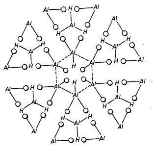
**BACKGROUND OF THE INVENTION****1. Field of the Invention**
The present invention is directed to a method of producing
hydroperoxy-group-containing aluminum compounds and such
compounds so produced. More specifically, the present
invention is directed to a method of producing
hydroperoxy-group-containing aluminum compounds in a sheet or
plate-like form, the compounds being transparent, appearing
polymeric in nature, and having the physical appearance of
mica.
**2. Description of Prior Art**
The patent literature describes various types of transparent
alumina and processes for producing such transparent alumina.
For example, U.S. Pat. No. 3,026,210 to R. L. Coble describes
a transparent alumina in which the alumina comprises high
density polycrystalline alumina bodies having in-line
transmission of not less than 10%/ml thickness of radiant
energy of wave length in the range from 0.30 micron to about
6.6 microns. Such transparent alumina bodies are prepared by
compacting a mixture of finely divided alumina with minor
additions of magnesia and firing the compact for predetermined
periods of time at a temperature not lower than about 1,700
DEG C., either in a vaccum or in a hydrogen environment.
U.S. Pat. No. 3,026,177 to P. D. S. St. Pierre, et al. also
involves the preparation of transparent polycrystalline
alumina. In accordance with this patent, the product is
produced by compacting a substantially pure, finely divided
alumina and subjecting the compact to a first firing in a
hydrogen atmosphere at a temperature of from about 1,650 DEG
C. to 1,750 DEG C. for a period of from 50 to 300 minutes and
thereafter, subjecting the alumina body to a second firing in
a hydrogen atmosphere at a temperature of from about 1800 DEG
C. to 2000 DEG C. for a period of not less than 15 minutes.
This second firing is said to improve the transparency of the
polycrystalline alumina.
U.S. Pat. No. Re. 27,083 in the name of Emile A. Klinger, et
al., describes a dense polycrystalline body of alumina which
has adequate transparency and high mechanical strength. Such
product is described as having an average size of grains of
less than 10 microns and a specific gravity greater than 3.96.
The polycrystalline body of fine grained alumina is obtained
by compacting a powder of aluminum oxide particles having a
particle size not substantially greater than 3 microns and
sintering the compacted body in the substantial absence of
gases having a molecular weight substantially greater than
that of hydrogen for a period of 3 to 30 minutes at a
temperature of 1700 DEG-1950 DEG C.
Also, U.S. Pat. No. 3,718,494 to Howard H. Jacobson describes
sheet-like alpha alumina having an average thickness of 10-250
m.mu. and major faces averaging 15-1000 m.mu.@2. Such
sheet-like alpha alumina is prepared by the formation of
mullite in the presence of a reactive flouride salt such as
cryolite.
With the exception of the last noted patent to Jacobson, each
of the above-described processes involves compacting a high
temperature sinter to produce transparent bodies of alumina.
None illustrates the direct production of an
aluminum-containing product, such as alumina, in a transparent
form directly in its formative reaction. Furthermore, in none
of these products is the alumina in a sheet-like or plate-like
form, having a physical structure similar to mica and
appearing polymeric in nature.
The preparation of an aluminum product having a substantial
amount of hydroperoxy groups is a desirable goal in that the
hydroperoxy groups create unique physical and chemical
characteristics in the aluminum compound. For example, unique
reactivity and catalytic properties are associated with the
presence of hydroperoxy groups. The use of hydrogen peroxide
to produce an alumina product, specifically as a hydro-forming
catalyst, is illustrated in U.S. Pat. No. 2,852,473 to
Welling.
The Welling patent relates to a process which involves a first
amalgamation of aluminum with a solution of a mercuric salt,
such as mercuric chloride, and subsequent contacting of the
amalgamated aluminum with a dilute aqueous solution of
hydrogen peroxide. With respect to the desired hardness,
porosity and surface area of the catalyst, a desirable product
is said to be obtained when the temperature of the reaction
medium is maintained between about 70 DEG C. and the boiling
point of the aqueous hydrogen peroxide. Generally, a
granulated aluminum is utilized to prepare this alumina
hydro-forming catalyst.
A process such as described in the Welling patent cannot
produce an alumina product in which the product is
transparent, in sheet or plate form and with the physical
appearance of mica. Moreover, a product such as that produced
by the process of Welling cannot be polymeric in nature. Still
further, the hydroperoxy group content of such product is
minimal due to the presence of a substantial amount of water
in the reaction system and the employment of a high
temperature reaction, since hydrogen peroxide is unstable
under the temperature conditions of Welling. Still further,
the use of a conventional amalgamated aluminum does not lend
itself to the preparation of an aluminum product containing
hydroperoxy groups and one which can be characterized as
transparent, in sheet or plate form and with the physical
appearance of mica. Such a product has now been obtained,
however, by adherence to the parameters of the present
invention.
**SUMMARY OF THE INVENTION**
The method of the present invention allows the formation of an
aluminum product having the physical appearance of mica, the
aluminum product further being characterized by the presence
of hydroperoxy groups, transparency and a sheet or plate-like
form, the aluminum product appearing polymeric in nature.
The aluminum-containing product is prepared by contacting and
reacting, at room temperature or below (a) a reactive metal
comprising aluminum metal of a purity of at least 99.9% by
weight permeated with a liquid metal selected from mercury,
gallium and indium/gallium alloys with (b) a liquid reactant
comprising (i) hydrogen peroxide in (ii) an anhydrous liquid
organic compound having no multiple carbon-to-carbon bonds.
The liquid reactant, i.e., hydrogen peroxide, in the anhydrous
liquid organic compound is substantially free of water, i.e.,
has up to about 10% by weight water, preferably as little
water as possible.
A further aluminum-containing product can be obtained by
firing the product obtained by the foregoing reaction at an
elevated temperature. This appears to effect a release of
hydrogen from the hydroperoxy-group-containing aluminum
product.
In an alternative embodiment, a hydroperoxy-group-containing
aluminum product having a metal deposited on or between sheets
or plates is obtained by adding a minor amount of a metal
powder or metallic salt to the reaction system.
**BRIEF DESCRIPTION OF THE DRAWINGS****FIG. 1 is a representation of the proposed chemical
structure of the aluminum-containing product of the present
invention as obtained by reaction between an activated
aluminum and hydrogen peroxide;****FIG. 2 is a representation of the proposed chemical
structure of the aluminum-containing product of FIG. 1,
after firing at elevated temperature; and****FIG. 3 comprises two superimposed infrared scans of the
aluminum-containing product; one as produced and one after
firing.**
**DESCRIPTION OF PREFERRED EMBODIMENTS**
As indicated previously, a hydroperoxy-group-containing
aluminum compound, specifically one having a
.gamma.-structure, is produced in accordance with the present
invention by the reaction of a reactive form of aluminum and a
liquid reactant comprising hydrogen peroxide in an anhydrous
liquid organic compound having no multiple carbon-to-carbon
bonds. Such hydroperoxy-group-containing aluminum compound is
characterized by transparency, and formation in a sheet or
plate-like form, the physical appearance of the product
resembling that of mica. In addition, the
hydroperoxy-group-containing aluminum compound appears
polymeric in nature.
The reactants necessary to achieve such
hydroperoxy-group-containing aluminum product will be
discussed individually below:
**Reactive Form of Aluminum**
A principal reactant in the preparation of the
hydroperoxy-group-containing aluminum product of the present
invention is aluminum metal, which has been activated or made
reactive through permeation by a second metal, i.e., a liquid
metal selected from mercury, gallium and indium/gallium
alloys. By "activated" or "reactive" is means that the
inter-crystalline structure of the aluminum is made uniquely
and exceptionally receptive to chemical reaction. A more
thorough description of the aluminum activation technique as
well as an explanation of the physio-chemical phenomena which
occur during activation is contained in copending application
Ser. No. 497,560, filed Aug. 15, 1974, which is hereby
incorporated by reference.
Basically, activation of the aluminum is carried out by
wetting the surface of the aluminum in the presence of a
source of hydrogen ions (protons), such as hydrochloric acid,
with a liquid second metal selected from mercury, gallium and
indium/gallium alloys until the aluminum has been permeated
with the second metal. Evidence has been developed to
establish that during this permeation of the aluminum the
grain boundaries of the aluminum are actually penetrated by
atoms of the second metal. This appears to create a
realignment of the aluminum grain boundaries which has the
effect of opening up the domains within the aluminum metal,
resulting in unique reactivity properties.
The activated aluminum which is utilized in the process of the
present invention shows many unique characteristics when
compared with the base untreated aluminum metal. One of these
is the dissolution of the aluminum and release of hydrogen
ions or protons when placed in a liquid medium containing a
source of hydrogen ions.
In preparing the activated aluminum, aluminum metal in the
form of relatively small rods, bars or sheets, etc.,
preferably substantially free of bends and twists, is
generally utilized. Preferably, soft aluminum metal having a
purity of at least 99.9% by weight is used. The use of an
aluminum metal with a substantial percentage of impurities is
disadvantageous in that activation requires substantially
longer periods of time. More importantly, there is the
tendency for the impurities to enter into and precipitate from
the subsequently formed products. Generally, however, the
impurities are leached from the aluminum during extended
periods of activation.
Using as an example the aluminum-mercury system, activation of
the aluminum can be effectively carried out by floating an
aluminum bar or rod on mercury in the presence of a hydrogen
ion donating medium. This hydrogen ion donating medium can be
an aqueous inorganic or organic acid, an aqueous alkaline
solution of an alcohol, etc. In principle, any hydrogen ion
source or hydrogen ion donating medium can be utilized. It is
hypothesized that the mercury is caused to penetrate and
diffuse through the aluminum in the form of a stable hydride
formed in situ by the reaction between the mercury metal and
hydrogen ions of the hydrogen ion donating medium. The ability
of mercury, indium and gallium to act in a similar fashion
appears to be associated with the hydride-forming capabilities
of these metals and the fact that each of these metals has an
atomic volume similar to that of hydrogen itself. This allows
the metals to penetrate and diffuse through the aluminum
either together with hydrogen or in the form of the hydride.
As will be apparent to those skilled in this art, the length
of time required for activation of the aluminum with mercury
will depend upon many factors, including the exposed surface
area, which is related to the hardness of the aluminum, and
the amount of impurities present in the aluminum. Longer times
are required for harder aluminums and those with greater
impurity contents. As a general rule, adequate activation of
aluminum rods with mercury can be achieved in a time period of
from about two hours to about 24 hours. When utilizing a
preferred soft grade of aluminum, activation can be achieved
in a period of from 8 to 12 hours.
When the aluminum is activated, it becomes embrittled and can
be easily broken, using a snapping action. By breaking the
aluminum and examining the grain structure at the break, one
can determine the degree to which the mercury has penetrated
and diffused throughout the aluminum. In accordance with the
preferred embodiment of the present invention, the desired
hydroperoxy-group-containing aluminum products are prepared
utilizing activated aluminum in which the mercury, gallium, or
indium/gallium alloy has penetrated and diffused entirely
throughout the aluminum structure.
In forming the activated aluminum, high temperatures should be
avoided since high temperatures appear to prevent grain
structure realignment due to lattice expansion. Generally, the
activation of aluminum with mercury can be carried out under
ambient temperature conditions, with a temperature in the
range or from 40 DEG F. to 100 DEG F. being preferred. When
utilizing gallium as the second metal, it is often desirable
to gently heat the gallium in order to maintain the gallium in
the liquid state, thereby allowing the permeation to more
effectively take place. Here again, however, excessive
temperatures should be avoided.
When forming the activated aluminum using gallium or an
indium/gallium alloy, the permeation and diffusion of the
gallium or indium/gallium through the aluminum rod may be
initiated merely be contacting one end of the aluminum rod
with the second metal or metals in the presence of the
hydrogen ion donating medium. The initiation of diffusion may
be observed by noting the surface wetting of the aluminum with
the second metal or metals above the point of contact. Further
diffusion of the gallium or indium/gallium alloy through the
entirety of the aluminum can then be continued by placing the
aluminum rod in an anhydrous organic liquid medium such as
alcohol, or the like, which is capable of donating hydrogen
ions for effecting further diffusion.
With respect to the indium/gallium alloys which may be used,
essentially any alloy composition will be suitable, ranging
from 90% by weight gallium and 10% by weight indium to 10% by
weight gallium and 90% by weight indium. When employing such
alloy, however a 50:50 weight mixture of gallium and indium is
extremely effective. As the percentage of indium is increased
in the indium/gallium alloy, there is an increasing tendency
for the activated aluminum to disintegrate. This does not
prevent production of the desired products of the present
invention, but could slightly complicate withdrawal of
unreacted activated aluminum from the reaction medium. The
amount of mercury, gallium or indium/gallium alloy which
penetrates and diffuses through the aluminum will depend, of
course, upon the length of treatment, temperature of treatment
and the ability of the aluminum to retain the second metal or
metals. As previously mentioned, it is preferred in accordance
with the present invention to employ an activated aluminum in
which the mercury, gallium or indium/gallium alloy has
penetrated entirely through the aluminum.
Generally, a soft aluminum will pick up and retain a maximum
of about 5% by weight of mercury during the activation
process, with typical pickups being in the 2.5 to 3.5% by
weight range. This amount of mercury is very effective to
achieve the desired results of the present invention. Even
with much smaller amounts of mercury, however, e.g., amounts
as low as 0.1%, the aluminum becomes activated and can be used
to produce the unique products of the present invention. It is
preferred, however, to operate with a mercury content within
the above specified range of about 2.5% to about 3.5% by
weight.
It has generally been found that an aluminum activated with
gallium or indium/gallium alloy is more active than the
mercury-activated aluminum. For this reason, the amount of
gallium or indium/gallium required to achieve suitable
activation is less than the amount of mercury required.
Generally, the aluminum will pick up and retain a maximum of
about 3% by weight gallium or indium/gallium alloy. However,
suitable activation can be achieved with as little as about
0.05 to about 1.0% by weight gallium or indium/gallium alloy
and it is preferred to utilize an amount in this range.
However, it has been found that even with amounts of these
metals as low as 0.01% by weight, very active aluminum
effective for the process of the present invention can be
provided.
**The Liquid Reactant**
The liquid reactant is separated into two portions, the first
being the active reactant, hydrogen peroxide, and the second
being a carrier for the hydrogen peroxide, specifically a
liquid organic compound having no multiple carbon-to-carbon
bonds.
The hydrogen peroxide reactant in accordance with the method
of the present invention is generally in the form of an
aqueous solution of hydrogen peroxide. However, since it is
necessary in accordance with the present invention to minimize
the amount of water present in the reaction system, the
aqueous solution of hydrogen peroxide should be somewhat
concentrated, with concentrations of 30% hydrogen peroxide or
greater being generally used, preferably 50% hydrogen peroxide
or greater. In addition, it is applicable in accordance with
the present invention to employ 100% hydrogen peroxide.
However, highly concentrated hydrogen peroxide solutions,
i.e., those of about 70-95% concentration must be handled with
care.
The vehicle or carrier for the hydrogen peroxide can
effectively comprise any liquid organic compound having only
single carbon-to-carbon bonds, i.e., one which contains no
carbon-to-carbon double bonds. Preferably, such liquid organic
compound is an anhydrous compound, again to effectively
minimize the water content of the reaction system. Typical
examples of such liquid organic compounds having no
carbon-to-carbon double bonds include, for example, alcohols,
particularly lower monohydric alcohols, such as methanol,
ethanol, isopropyl alcohol, n-butyl alcohol, isobutyl alcohol,
amyl alcohol, hexanol, etc.; ketones, particularly ketones of
up to six carbon atoms, including for example, formaldehyde,
acetaldehyde, etc.
The absence of carbon-to-carbon double bonds in the liquid
organic compound acting as a vehicle or carrier for the
hydrogen peroxide is important since compounds with
carbon-to-carbon double bonds tend to enter into reaction with
the activated or reactive aluminum, and in some instances,
take part in polymerization reactions. Accordingly, such
reactions which may tend to interfere with the interaction and
reaction between the hydrogen peroxide and activated aluminum
should be avoided. Accordingly, any liquid organic compound
which does not readily react with the activated aluminum under
the conditions of the present method can be effectively
employed as the carrier or vehicle for the hydrogen peroxide.
In order to minimize the water content of the liquid reactant
in accordance with the present invention, the carrier or
vehicle liquid is generally employed in a large amount with
respect to the hydrogen peroxide solution. As indicated
previously, the total water content of the liquid reactant
should not exceed about 10% by weight. Generally, such water
content is about 2-5% by weight. This is effectively achieved
by employing a ratio of the liquid organic compound having no
carbon-to-carbon double bonds to the aqueous hydrogen peroxide
solution of from about 2:1 to about 20:1 or more. Certainly it
should be apparent that even greater amounts of the carrier or
vehicle when compared to the aqueous hydrogen peroxide
solution can be utilized to even further minimize the amount
of water present in the liquid reactant system.
The use of an anhydrous liquid organic compound is
advantageous in the process of the present invention since the
anhydrous organic liquid will have the tendency to tie up the
small percentage of free water present in the reaction system,
such as in the aqueous hydrogen peroxide reactant.
Accordingly, the amount of anhydrous liquid organic compound
based on the amount of hydrogen peroxide should preferably be
sufficient to tie up any free water present in the system.
This allows the reaction system to be substantially free of
free water. Accordingly, as used throughout, the expression
"substantial absence of water" is meant to embrace the above
limitations, specifically the limitation that a maximum of 10%
water can be present in the reaction system.
**Optional Metallic Reactant**
It is possible in accordance with the present invention to
deposit on the hydroperoxy-group-containing aluminum compound
a metal or combination of metals by employing in the reaction
system a powdered metal or metallic salt capable of depositing
the metal under the conditions of the reaction. By employing
such metal powder of metal salt in the process of the present
invention, the metal or combination of metals are deposited on
the hydroperoxy-group-containing aluminum product between
sheets or flakes. This can be carried out to provide
coloration to the hydroperoxy-group-containing aluminum
compound, such as in the preparation of a metallic pigment, or
can be used to deposit a catalytic component, such as
platinum, palladium, etc., on the hydroperoxy-group-containing
aluminum compound, which provides a support for the catalyst.
Typical metals applicable in accordance with the present
invention include, for example, platinum, palladium, chromium,
manganese, titanium, silver, gold, iron, cobalt, magnesium,
cadmium, nickel, copper, zinc, zirconium, alkali metals, etc.
Again, where possible, these metals can be utilized in the
form of the metallic powder or the salts of these metals which
are capable of depositing the metal under the conditions of
the reaction can be utilized. Typical salts include, for
example, the oxide, nitrate, or chloride of the respective
metals. The salt of the metal should be one which is soluble
in the carrier medium, e.g., alcohol, utilized in the reaction
system of the present invention.
Generally, it is necessary only to deposit a very minor amount
of the metal onto the hydroperoxy-group-containing aluminum
compound to achieve the desired coloration and/or catalytic
properties. Accordingly, such metal or metallic salt should be
employed in this alternative embodiment in that amount. An
amount of about 0.01% to about 5% by weight based upon the
weight of the reactive or activated aluminum is sufficient for
this purpose. Here again, however, somewhat lesser or greater
amounts can be utilized to achieve particular purposes.
**Reaction Parameters**
As indicated previously, the process of the present invention
to prepare the hydroperoxy-group-containing aluminum compound
is carried out by simply contacting and reacting the reactive
aluminum with a liquid comprising (i) hydrogen peroxide in
(ii) an anhydrous liquid organic compound having no multiple
carbon-to-carbon bonds. In addition, as previously indicated,
such reaction is carried out in the substantial absence of
water. Still further, it is important in accordance with the
present invention that the reaction be carried out without
heating, i.e., at room temperature or below, preferably below
room temperature, by cooling the reaction system during the
reaction. This can be achieved in any suitable manner, such as
by carrying out the reaction with the reaction vessel immersed
in an ice bath.
The process of the present invention is preferably carried out
by adding the reactive aluminum in rod, bar or sheet form to a
suitable reaction vessel, preferably vertically oriented, with
the activated aluminum rod being immersed in the liquid
reaction system comprising the hydrogen peroxide in the
anhydrous liquid organic compound having no multiple
carbon-to-carbon bonds. It is totally unnecessary to use any
sophisticated reaction system and unnecessary to provide any
agitation of the reaction system. Clearly, all that is
necessary in accordance with the present invention is to bring
together the hydrogen peroxide and reactive or activated
aluminum in a suitable reaction vessel in the substantial
absence of water, and at room temperature or below.
In accordance with the process of the present invention, by
maintaining reactive contact between the hydrogen peroxide and
reactive or activated aluminum, it appears that a layer of
hydrogen peroxide forms over the surface of the activated or
reactive aluminum. Another layer of the hydrogen peroxide
forms over the first layer and apparently, successive layers
build up in this manner.
In accordance with the above hypothesized formation of the
hydroperoxy-group-containing aluminum compound, it is presumed
that the hydrogen peroxide groups alternate in accordance with
the charge pattern distribution on the atoms therein. Highly
concentrated hydrogen peroxide has a tendency to produce
hydroperoxy groups which are relatively stable radicals. It is
hypothesized that during the production of such hydroperoxy
groups, the associated hydrogen ion diffuses into and then out
of the reaction or activated aluminum. As this reaction
continues, the sheet or flake-like form of the
hydroperoxy-group-containing aluminum compound is developed in
accordance with the hypothesized atomic structure illustrated
in FIG. 1.
Referring to FIG. 1, it is noted that from the proposed or
hypothesized model, there is a sharing of hydroperoxy groups
by the aluminum atoms. Therefore, a more accurate
representation of the basic building block of the
hydroperoxy-group-containing aluminum compound of the present
invention may be the following:
Al4 (HO2)3
each of these formuli and atomic structures are merely
hypothesized, however, and there is no intention that this
invention is limited thereto. Rather, such hypotheses are
presented for a more clear understanding of the process of the
present invention.
As indicated previously, the hydroperoxy-group-containing
aluminum compound of the present invention is formed as sheets
or flakes which resemble mica in physical appearance. These
sheets or flakes which are successively built up on the
reactive or activated aluminum rod separate or flake off of
the aluminum. The product can then be easily removed, as by
decanting the liquid, filtration, etc.
The individual layers of the hydroperoxy-group-containing
aluminum compound in accordance with the present invention are
transparent to natural light. In this regard, such layers
resemble window glass in their translucent properties.
However, when multiple layers of the
hydroperoxy-group-containing aluminum compound are built up,
the product is pearlescent due to the light refraction
associated with the multiple layers.
While the hydroperoxy-group-containing aluminum compound is
formed in the above-described reaction as a clear, transparent
product, a pigment-type product, i.e., one which is colored,
can be produced as previously described by including a metal
powder or soluble metal salt in the reaction system.
Accordingly, various colored products can be produced. In
addition, by the judicious selection of the metallic
component, highly catalytic products with the
hydroperoxy-group-containing aluminum compound as a support
can be produced.
The hydroperoxy-group-containing aluminum compound of the
present invention has the property of being stable over a wide
temperature range. However, when this product is subjected to
a greatly elevated temperature in the order of 2000 DEG C. or
higher, hydrogen ions are released from the structure of the
hydroperoxy-group-containing aluminum compound. It is
hypothesized that such release of hydrogen atoms results in a
product having a structure as illustrated in FIG. 2.
It is noted from FIG. 2 that the proposed structure
corresponds to that of sapphire. Presumably, the basic
building block of the hydroperoxy-group-containing aluminum
compound after firing at a temperature in the order of 2000
DEG C. takes the form as follows:
Al4 (O2)3
it is interesting to compare the reaction of the
hydroperoxy-group-containing aluminum compound with sulfuric
acid, both before and after firing. Before firing, it appears
as though a sulfite is formed, thereby illustrating that the
aluminum is in an ionic form. However, after firing, no
reaction with sulfuric acid appears to take place.
FIG. 3 represents infrared scans of the
hydroperoxy-group-containing aluminum compound both before and
after firing. The wide absorption band in the region of 3400
cm@@-1 in both infrared scans tends to establish the presence
of hydroperoxy groups, rather than hydroxy groups which would
be easily lost in firing. The change which takes place in the
region of 900 cm@@-1 is believed to be associated with the
breaking of hydrogen bonds and release of hydrogen from the
structure.
The present invention will now be described by reference to
the following specific examples. It should be understood,
however, that such examples are presented for purposes of
illustration only, and the present invention can not under any
circumstances be deemed limited thereby.
Unless otherwise stated in the following examples, and
throughout thespecification, all parts and percentages are by
weight.
**EXAMPLE 1**
A high purity aluminum rod of about 100 grams and having a
diameter of about one-half inch is activated by permeation
with mercury in the presence of hydrochloric acid. The
aluminum rod is saturated to the point of having about 3% by
weight of mercury. The activated rod is then washed thoroughly
with distilled water in order to remove the presence of
residual hydrochloric acid or any chloride compound which
might have been formed during the treatment. A tall, narrow
vessel is filled with a mixture of about 1000 ml of anhydrous
methanol and about 50 ml of hydrogen peroxide having a
concentration of 30%. The activated aluminum rod is placed
into the vessel so that it retains a vertical position. This
is desirable in order to increase the available surface area
to the reactants and to permit the free conduction and
convection of heat away from the reactive aluminum rod.
Cooling is applied where necessary to maintain the temperature
at room temperature or below. The activated aluminum rod is
submerged throughout the reaction. The reaction which takes
place produces thin sheets which appear to peel off of the
activated aluminum rod and accumulate in the vessel. It is
desirable not to disturb or jar the vessel in order to avoid
shattering the sheets. The sheets formed can be removed by
removing the activated aluminum rod and then decanting the
liquid. The final product can then be washed in distilled
water and dried.
**EXAMPLE 2**
Example 1 is repeated with the use of an equivalent amount of
anhydrous ethyl alcohol instead of anhydrous methanol.
**EXAMPLE 3**
Example 1 is repeated utilizing an equivalent amount of
ethylene glycol in lieu of methanol.
**EXAMPLE 4**
Example 1 is repeated utilizing an equivalent amount of
isopropyl alcohol in lieu of methanol.
**EXAMPLE 5**
Examples 1-4 are repeated with the exception that a 50%
concentrated aqueous solution of hydrogen peroxide is used and
the vessel is cooled with an ice pack.
**EXAMPLE 6**
Examples 1-4 are repeated with the exception that a 70%
concentrated solution of hydrogen peroxide is used and the
vessel is cooled with an ice pack.
**EXAMPLE 7**
Following the procedure of Example 1, a mercury prepared
activated aluminum rod is reacted with 800 ml of anhydrous
ethyl alcohol mixed with 200 ml of hydrogen peroxide having a
concentration of 50%. A similar product is produced.
**EXAMPLE 8**
Example 7 is repeated except that 1 g of chromium oxide or
chromium nitrate is mixed into the solution before the
activated aluminum rod is inserted. This results in a green
product with chromium deposited thereon.
**EXAMPLE 9**
Example 7 is repeated except that either manganese oxide or
manganese nitrate is mixed into the solution before the
activated aluminum rod is inserted. A pink product is
produced.
**EXAMPLE 10**
The procedure of Example 7 is repeated except that 1 g of
titanium nitrate or titanium oxide is added to the solution
before the activated aluminum rod is inserted. A white product
is produced.
**EXAMPLE 11**
The procedure of Example 7 is repeated except that 1 g of
cobalt oxide or cobalt nitrate is added to the solution before
the activated aluminum rod is inserted. A blue smokey product
results.
**EXAMPLE 12**
The procedure of Example 7 is repeated except that 1 g of
magnesium oxide or magnesium nitrate is added to the liquid
before the activated aluminum rod is inserted.
**EXAMPLE 13**
The procedure of Example 7 is repeated except that 1 g of
ferric oxide or ferric nitrate is added to the liquid before
the activated aluminum rod is inserted. A reddish or ruby
colored product results.
**EXAMPLE 14**
The procedure of Example 7 is repeated except that 1 g of
cadmium oxide or cadmium nitrate is added to the liquid before
the activated aluminum rod is inserted.
**EXAMPLE 15**
The procedure of Example 7 is repeated except that 1 g of
nickel oxide or nickel nitrate is added to the liquid before
the activated aluminum rod is inserted.
**EXAMPLE 16**
The procedure of Example 7 is repeated except that 1 g of
zirconium oxide or zirconium nitrate is added to the liquid
before the activated aluminum rod is inserted.
**EXAMPLE 17**
The procedure of Example 7 is repeated except that 1 g of
potassium chromate is added to the liquid before the activated
aluminum rod is inserted.
**EXAMPLE 18**
The procedure of Example 7 is repeated except that 1 g of
cupric nitrate is added to the liquid before the activated
aluminum rod is inserted.
**EXAMPLE 19**
The procedure of Example 7 is repeated except that 1 g of zinc
oxide or zinc nitrate is added to the liquid before the
activated aluminum rod is inserted.
**EXAMPLE 20**
A catalyst supported on the hydroperoxy-group-containing
aluminum compound of the present invention is prepared by a
procedure similar to that of Example 1. A mercury prepared
activated aluminum rod permeated with approximately 3% by
weight mercury is contacted and reacted with 1000 ml anhydrous
alcohol (SD40) with 100 ml of hydrogen peroxide, a 50% aqueous
solution. Some 30 drops of silver nitrate are added to the
alcohol-hydrogen peroxide liquid system prior to introduction
of the activated aluminum rod. This results in the deposition
of silver on the sheet or plate-like
hydroperoxy-group-containing aluminum product.
**EXAMPLE 21**
The procedure of Example 20 is repeated with the exception
that 30 drops of gold chloride are utilized in lieu of the
silver nitrate. This results in the deposition of gold on the
hydroxy-group-containing aluminum product.
**EXAMPLE 22**
The procedure of Example 20 is repeated with the exception
that 24 drops of platinum chloride are utilized in lieu of the
silver nitrate. The resulting product comprises a sheet or
plate-like hydroperoxy-group-containing aluminum support with
platinum deposited thereon. This product shows excellent
catalytic activity.
**EXAMPLE 23**
The procedure of Example 20 is again repeated with the
exception that 6 drops of palladium chloride are utilized in
lieu of the silver nitrate. This product comprises palladium
metal deposited on the hydroperoxy-group-containing aluminum
support. Again, excellent catalytic activity is illustrated.
**EXAMPLE 24**
The hydroperoxy-group-containing aluminum product formed in
sheet or plate-like form in accordance with Example 1 is fired
in an oven at a temperature in the order of 2000 DEG C. This
firing results in the release of hydrogen atoms from the solid
sheet-like product. This fired product is particularly
suitable for electronic support applications.
While the present invention has been described primarily with
regard to the foregoing specific exemplification and reference
to specific embodiments, it should be understood that the
present invention can not under any circumstances be deemed
limited thereto, but rather, must be construed as broadly as
all of any equivalents thereof.
---
**Metallic-organo-peroxide and
organo-metallic-peroxide**
**US4017527**
**[ [PDF](US4017527A.pdf) ]**
BACKGROUND OF THE
INVENTION
The present invention relates to a method for the
formation of metallic-organo-peroxides and organo-metallic
peroxides and to such compounds so produced.
Many methods for forming organo-peroxides are known.
Reference is made to the book, "Hydrogen Peroxide in
Organic Chemistry" by John G. Wallace, published by the
Electro Chemical Department of EIdu Pont De Neumours and
Company.
Generally, an organic peroxide is defined as a derivative
formed by replacing one or both hydrogen atoms of hydrogen
peroxide by an organic radical. The present method
produces compounds which include a metal atom bonded to an
organic radical and a peroxide type bonded to the organic
radical. The peroxide group is the oxygen to oxygen type
bond is which a hydrogen atom can be connected to one of
the oxygen atoms. The method of the present invention also
produces a product wherein the organic radical has a
metallic atom bonded to it and the peroxide group is
bonded to the metal atom. The differences in the types of
products produced gives rise to the distinction between
the description of the product as being on the one hand a,
metallic-organo-peroxides and on the other hand an,
organo-metallic-peroxides.
One elementary method of producing an organic peroxide
makes use of the fact that a strong aliphatic acid
solution with hydrogen peroxide exists in equilibrium with
the corresponding organic peracid. ##STR1##
However, in the absence of a strong acid catalyst, such as
a mineral acid, the attainment of equilibrium is
impractically slow, especially at temperatures below 40
DEG C. At higher temperatures, it is difficult to prevent
the excessive loss of active oxygen unless the oxidizable
organic substance is also present to react with the
organic peracid as it forms. For this reason, it is common
practice, whenever possible, to employ hydrogen peroxide
under conditions for the in situ formation of the organic
peracid at temperatures ranging up to the boiling point of
the aliphatic acid.
The peracid formed in situ can be reacted with an olefinic
material to produce an epoxy (oxirane) compound as a
primary product. ##STR2##
The reaction is, of course, two-staged, since the peracid
must be formed first.
Common organic peracid systems include glacial acetic acid
or formic acid with hydrogen peroxide. The organic
peracids thus formed are unstable and considered a hazard
particularly when the organic peracid is relatively
concentrated.
It is known that the mild oxidizing action of hydrogen
peroxide is increased considerably by use of certain
metallic catalysts. One example of metallic catalyst is
ferrous sulfate which is employed in a redox system:
FE@+@+-- Fe@+@+@+
It has been employed with hydrogen peroxide and is
generally known as Fenton's Reagent. Other catalyst
include osmium and tungstic oxides employed to hydroxylate
aromatic and unsaturated hydrocarbons and to effect other
oxidations. These additional catalysts are classed as
Milas' Reagents which together with Fenton's Reagent
constitute the bulk of the metal activated hydrogen
peroxide systems. Hydrogen peroxide in metal-activated
systems reacts as though it was dissociating into two
hydroxyl radicals.
Fenton's oxidations are, in fact, believed to proceed
through the intermediate formation of hydroxyl free
radicals:
Fe@+@+@+H2 O2 .fwdarw.Fe@+@+@++OH@-+OH
the Fe@+@+--F@+@+@+ systems, and such other redox systems
as Cu@+--Cu@+@+, are normally employed with hydrogen
peroxide in aqueous acid medium. A small amount of
sulfuric acid is added to an aqueous solution of ferrous
sulfate heptahydrate so that Fenton's oxidations are
carried out at a pH of 1-4.In a less acid solution, the
reaction efficiency is decreased, and hydrogen peroxide is
catalytically decomposed.
Other metal-activated systems include in decreasing order
of catalytic efficiency the following:
Os O4, WO3, MoO3, SeO2, CrO3, V2 O5, TiO2 and Ta2 Os
Derivatives of the aforementioned catalyst, such as
phosphotungstic acids (e.g. H3 PO4 12WO3) are also
effective as catalysts for hydrogen peroxide.
The prior art shows four general methods of incorporating
the peroxide bond (--OO--) into organic molecules. These
methods include auto-oxidation. ozonization, the
association of oxygenated free radicals, and the addition
and substitution reactions of hydrogen peroxide and
hydroperoxides. Typically, hydrogen peroxide is reacted
with acids, anhydrides, esters, alcohols, organic sulfates
and sulfonates, carbonyl compounds, and organic chlorine
compounds to produce organic peroxides.
The reaction of acids anhydrides and esters with hydrogen
peroxide ordinarily lead to the formation or organic
peracids, although other organic percompounds may result.
The most polular method of preparing a peracid is by
mixing hydrogen peroxide and an aliphatic acid in the
presence of a strong acid catalyst such as sulfuric acid.
Typically an equimolar mixture of high strength hydrogen
peroxide and acetic acid with one percent sulfuric acid
catalyst reaches equilibrium after standing for 12 to 16
hours.
The resin techinque for peracetic acid formation is
considered much faster and permits continuous or batchwise
preparation.
The resin technique or peracetic acid formation is
operated simply by passing a mixture of glacial acetic
acid and hydrogen peroxide through a cation exchange resin
column. The column contains polystyrene sulfonic acid
resin which has been treated with glacial acetic acid to
remove excess water. Under conditions for operation of the
resin technique, a contact time of 12 to 16 minutes of
about 45 DEG C is sufficient for maximum conversion of
hydrogen peroxide to operacetic acid. The serious drawback
in this method is that it requires high strength hydrogen
peroxide and thus creates a serious hazard.
A common procedure for converting an alcohol, R--O--H, to
a hydroperoxide, R--OOH, consists of reacting hydrogen
peroxide and tertiary alcohols is strong sulfuric acid.
The reaction is believed to involve the formation of an
intermediate sulfate and, therefore, is similar to the
alkylation of hydrogen peroxide by dialkyl sulfates. The
reaction often results in serious explosions, although the
final products of such reactions are relatively stable.
Prior art methods do not produce peroxide products with
primary or secondary alcohols very easily. Mixtures of a
tertiary alcohol and hydrogen peroxide have been used as
germicides, fungicides, bleaching agents, and peroxide
reagents.
The strong sulfuric acid used in the hydrogen
peroxide-alcohol reaction is sometimes replaced by
heteropolyacids having multiple inorganic acid radicals.
The heteropolyacids which are soluble in ether, contain
the elements of phosphorous, silicon, or boron,
coordinated with a metallic oxide such as tungsten oxide.
The characteristic solubility of heteropolyacids allows
the preparation of alkyl hydroperoxides to be carried out
in ether.
The known methods of converting carbinols of many types to
hydroperoxides and disubstituted peroxides makes use of
strong sulfuric acid as a catalyst. Typically, acetylene
peroxides are formed by the interaction of hydrogen
peroxide and the hydroxyl group of acetylenic carbinols in
the presence of strong sulfuric acid. The peroxides thus
formed are unusually stable despite the presence of the
acetylenic bond.
Dialkyl sulfates and alkyl hydrogen sulfates can be used
to produce hydroperoxides and dialkyl peroxides by a
reaction with alkaline hydrogen peroxide. These peroxides
are often used as polymerization catalysts and diesel fuel
additives. Typically, primary and secondary dialkyl
peroxides are prepared by the alkylation of hydrogen
peroxide with alkyl methane sulfonates in liquid alkaline
methanolic solution. A known method for producing sodium
peroxy sulfonates is carried out by reacting a sulfonic
acid such as naphthalene sulfonic acid and sodium peroxide
in a liquid medium. The operation is conducted in a cold
environment to reduce the violence of the reaction. The
peroxy product obtained has aproximately 6% active oxygen
and is considered useful as a bleaching agent or
insecticide.
Olefins have been transformed to hydroperoxides in a
reaction which amounts to the addition of hydrogen
peroxide to the double bond. The reaction, however, is
conducted in strong sulfuric acid according to known
methods and probably involves the formation of an
intermediate sulfate. ##STR3##
The preparation typically takes place at below 0 DEG C and
takes several hours.
It is known that hydrogen peroxide can be reacted with an
aldehyde of a ketone in the presence of a catalyst to form
a peroxide compound. The following equilibrium is believed
to occur for an aldehyde and hydrogen peroxide: ##STR4##
Typically, formaldehyde is treated with hydrogen peroxide
in ether in the presence of P2 O5. The peroxide product is
very explosive. Both cyclic ketones and aliphatic ketones
have a tendency to form stable but hazardous peroxides. As
a rule, known methods produce unstable peroxides of
aromatic ketones and aromatic aldehydes because of the
greater ease of migration of the phenyl radicals attached
to the carbonyl carbon.
It is known that organic peroxides can be formed by
reacting hydrogen peroxide with organic chlorine
compounds. The reaction is generally conducted in the
presence of a chlorine acceptor which may be caustic or
organic bases such as pyridine.
**SUMMARY OF THE INVENTION**
One of the principal objects of the invention is to
provide a peroxide compound comprising the steps of
preparing a reactive aluminum and reacting the reactive
aluminum with a liquid mixture of hydrogen peroxide and an
organic compond. Another object of the present invention
is to provide a method for forming a
metallic-organoperoxide comprising the steps of forming a
reactive aluminum and contacting a liquid mixture of
hydrogen peroxide and an organic compound with the
reactive aluminum. Another object of the invention is to
provide a method for forming an organo-metallic-peroxide
comprising the steps of forming a reactive aluminum and
contacting a liquid mixture of hydrogen peroxide and an
organic compound with the reactive aluminum.
Another object of the present invention is to provide a
method of forming an alcohol peroxide comprising the steps
of forming a reactive aluminum and contacting a liquid
mixture of an alcohol and hydrogen peroxide with the
reactive aluminum.
Another object of the invention is to provide a method of
forming an aldehyde peroxide comprising the steps of
forming a reaction aluminum and containing a liquid
mixture of an aldehyde and hydrogen peroxide with the
reactive aluminum.
Another object of the invention is to provide a method of
forming a ketone peroxide comprising the steps of forming
a reactive aluminum and contacting a liquid mixture of a
ketone and hydrogen peroxide with the reactive aluminum.
The invention accordingly comprises the several steps and
the relation of one or more of such steps with respect to
each of the others, or as exemplified in the following
detailed disclosure, and the scope of the applicaton of
which will be indicated in the claims.
**THE INVENTION**
The present invention is focused on the utilization of the
catalytic properties of a reactive aluminum prepared by
the methods described in co-pending patent application,
"Catalytic Electrode", Ser. No. 211,979, filed Dec. 27,
1971, now abandoned.
The reactive aluminum in the present disclosure
corresponds to the aluminum catalytic electrode described
in the aforementioned patent application.
Generally, a reactive aluminum is prepared by contacting
highly pure aluminum in the presence of a hydrogen ion
source with a metal which can form a hydride. The hydrogen
ion source can be inorganic acid or the like or an
inorganic acid such as citric acid or acetic acid or the
like. The reactive aluminum in an alkali solution such as
water and sodium hydroxide will serve as a hydrogen ion
source for the formation of another reactive aluminum.
The metal for forming the reactive aluminum can be an
element or an alloy. Preferably, the metal is gallium, or
indium or an alloy of the two or mercury. A desirable
characteristic of the metal is that it is soft and pliable
and preferably a liquid during the process in order to
permit the rapid permeation through the aluminum. The
general rule is that an element with an atomic volume near
that of hydrogen is preferred for this metal.
It should be understood that the term "highly pure" herein
means greater than 99% and that purities in the order of
99.9 and 99.99% are preferable.
One simple method of preparing a reactive aluminum is to
use an aluminum piece, such as a rod 99.99% pure having a
length of 3 inches and a diameter of a half inch. The
aluminum rod is placed on its side in a glass dish and
sufficient 2N acid, such as hydrochloric acid, is added to
cover the aluminum rod. The aluminum rod is contacted with
the metal such as mercury or gallium and the metal is
given time to permeate through the aluminum rod. Of
course, the aluminum rod can be treated in a vertical
position if desired and a rod shape is not necessary.
Other shapes may be used.
The concentration of the acid can cover the broadest range
to even includde neutral water. The choice of the hydrogen
ion source such as an acid will depend upon the peroxide
compound to be formed and the concern over impurities.
It is preferable to prepare the aluminum rod for the
reaction by at least partially stripping the aluminum
oxide coating which has formed on the surface due to the
exposure to air and moisture. If the aluminum rod has been
stripped, then hot water can serve as the hydrogen ion
source. Otherwise, it may be desirable to start out with
an acid to strip off the oxide coating on the aluminum rod
in order to initiate the reaction to form the reactive
aluminum as quickly as possible. Of course, the aluminum
rod may be striped mechanically with sandpaper of a file
or the like.
The inter-reaction which occurs between the aluminum rod
and the acid, gives rise at the start to the formation of
large bubbles which rise up to the surface through the
acid. After a while it will be observed that instead of
large bubbles forming at the top of the aluminum rod and
then breaking free and rising to the surface of the acid,
tiny bubbles will be eminating from many parts of the
upper surface of the aluminum rod. The occurrence of the
multitude of tiny bubbles indicates that the aluminum rod
is being converted into a "reactive" aluminum.
Generally, the aluminum rod will take up or absorb from
0.1 to 5 percent of the mercury by weight depending upon
how long the reaction is permitted to continue. A range of
2 to 3 percent of the mercury by weight is desired for
many applications. However, in some applications as little
as 0.1 percent of the mercury by weight is preferred.
The reaction can be stopped on the basis of the increased
weight of the aluminum rod due to the absorption of the
metal or due to the production of a multitude of tiny
bubbles for a period of 10 to 15 minutes or due to the
observance of the hydrolysis of water when the aluminum
rod being treated is placed therein.
An aluminum rod treated as described, displays suprisingly
active catalytic properties not at all suggested by the
prior art. The prior art has recognized that aluminum and
an amalgam of aluminum exhibit catalytic properties. It is
of considerable significance that the treatment of highly
pure aluminum as described herein exhibits catalytic and
initiating properties that far exceed prior art
contemplation.
Another method of preparing a reactive aluminum uses
gallium instead of mercury. The same aluminum rod is
placed in a glass dish and covered with hydrochloric acid
and one end of the aluminum rod is contacted with the
gallium having a mass from 1 to 3 percent of the aluminum
rod. The treatment takes from 10 to 15 minutes depending
upon how well the oxide coating on the aluminum rod has
been removed at the point of contact of the gallium and
the aluminum rod. A fairly clean part of the aluminum rod
is indicated by the observance of large bubbles generated
thereat.
It is desirable to dip a reactive aluminum formed with
gallium into anhydrous alcohol immediately after
completion of the process in order to prevent the
formation of a brownish compound on the aluminum rod
thereafter.
The amount of the metal in the aluminum rod can be varied
in accordance with applications. In general, if a high
percent of the metal by weight is desired, quick cooling
of the reactive aluminum rod after formation will prevent
the squeezing out of the metal due to an exothermic
reaction. Water is convenient for this purpose for a
reactive aluminum formed with mercury. However, in cases
where it is desired to reduce the amount of, say, mercury
from several percent by weight to, say, 0.1% by weight,
the reactive aluminum can be heated to squeeze out the
mercury.
From the above, it is clear herein, including the claims,
what is meant by a "reactive aluminum".
The reactive aluminum exhibits an aligned matrix and, it
is believed, capable of converting at least partially to a
hydride at one or more valences and produces
Al@+@+@+,e@-,H+,OH@-,HO2 @-@-, and O@-@- radicals
depending upon the fluid contacting the reactive aluminum.
Where the fluid is hydrogen peroxide, it is believed that
O2 @- and O2 @-@- radicals are produced in addition to the
aforementioned radicals.
Certain impurities such as copper and iron, inhibit the
formation of a reactive aluminum and so should be avoided
in the aluminum rod. Impurities which inhibit or promote
the reaction are given in the aforementioned catalytic
electrode application.
An important aspect of the present is the realization that
the aforementioned treatment of highly pure aluminum
results in a reactive aluminum which can bring about a
reaction with an organic compound and hydrogen peroxide to
form a peroxide compound. The reactive aluminum not only
brings about the formation of the peroxide compound, but
further results in the aluminum from the reactive aluminum
entering into the peroxide compound to form a part
thereof. The amount of aluminum which forms a part of the
peroxide compound can vary from a fraction of a percent to
5 percent or more.
Generally, the reaction time for the production for most
of the peroxides in accordance with the present invention
is considerably shorter than the time taken by prior art
methods. The rate of the reaction for the production of a
peroxide in accordance with the present method will be
determined by well known parameters, such as the
concentration of the hydrogen peroxide, the temperature of
the constituents, the quantity of the reactive aluminum,
and other factors.
If a reaction is permitted to proceed too rapidly so that
the exothermic reaction elevates the temperature of the
constituents, there is a possibility that the hydrogen
peroxide will tend to break up into water and oxygen and
thereby reduce the concentration of the hydrogen peroxide.
As a result, there will be fewer peroxide groups available
for the formation of the desired peroxide compound.
One approach for controlling the reaction rate is to add
the hydrogen peroxide a little at a time. Of course, this
presumes the presence of a liquid organic compound already
present in order to form the mixture with the hydrogen
peroxide.
Of course, a dilute hydrogen peroxide can be used in order
to reduce the exothermic reaction to produce a relatively
low-grade peroxide compound without the incidence of an
elevated temperature or a reaction which requires some
monitoring.
Generally, the atomic bonding in an organic peroxide
formed by the present methods will be dependent upon the
bonding that is present in the organic compound used in
the reaction with hydrogen peroxide in the presence of the
reactive aluminum. For example, it is well known that
double bonds in organic compounds tend to be preferred
sites for inter-reaction or reactions in general.
Generally, an organic compond having only single bonds can
be reacted with hydrogen peroxide in the presence of the
reactive aluminum to form an organic peroxide which shows
hydroperoxide groups attached to the aluminum atoms with
the organic groups coordinated about the aluminum atom.
The precise structure or organization is not known. In
practicing the present method to form an organic peroxide
with an organic compound having single bonds, it is
preferred to use a relatively dilute solution of hydrogen
peroxide so as to provide a readily available source of
hydroxyl radicals. A water solution of hydrogen peroxide
between 3 to about 10% is preferable. Higher
concentrations of hydrogen peroxide can be used but will
tend to produce an inorganic peroxide in competition with
the formation of the organic-metallic-peroxide described.
The examples given herein illustrate the use of single
bonded organic compounds such as alcohols, ketones, and
aldehydes.
In the case where the organic compounds include other than
single bonds such as double bonds, triple bonds, multiple
bonds in general, or the like, an organic peroxide having
a peroxide or hydroperoxide group attached directly to an
organic group can be produced. Since the organic peroxide
product in this case also includes an aluminum atom, it is
proper to describe such products as a
metallic-organic-peroxides,
The presence of a ring structure in the organic compounds
does not hereto affect the formation of an organic
peroxide by the present methods. The organic compounds
having at least one multiple bond include, the so-called
vinyl-type compound. Basically, a vinyl-type compound is
characterized by the formula ##STR5## The R or R' can be a
member of the aliphatic series. When a nitrile group
replaces the carboxyl group then acrylonitrile is
obtained. For an amide group acrylamide is obtained while
for a aldehyde group acrolein or acrylaldehyde is
obtained. Either the R or R' or both can be replaced by an
halide or an active halide.
It is interesting to note that in the article entitled,
"Thermochemistry of the Hydrogen Polyoxides H2 O3 and H2
O4 " by Paul A. Giguere, published in the Transactions New
York Academy of Sciences, that the presence of three
radicals of H2 O3 and H2 O4 were prepared and measured
under the extreme conditions of temperature of less than
100 DEG K. Furthermore, this article reports to indicates
that the formation of higher order hydrogen polyoxides are
extremely difficult and require extreme temperature and
pressure requirements. Although no limitation is intended
to be suggested by the presentation of theories related to
the operation of the present invention, it is believed
that in carrying out the present invention there is a
considerable production of radicals of H2 O3 @-@- and H2
O4 @-@- due to the reactive aluminum reacting with the
hydrogen peroxide. It has been observed that during the
formation of an organic peroxide by the method of the
present invention the removal of the reactive aluminum
from the mixture into air produced a red meruric oxide on
the reactive aluminum which had been prepared with
mercury. The formation of red mercuric oxide rather than
black mercuric oxide is an indication of O2 @- radicals
which points to the aforementioned polyoxide radicals. In
another experiment, part of an organic peroxide prepared
with a carboxylic acid, was contacted with some mercury
and immediately produced red mercuric oxide which for the
same reason given previously, tends to confirm the
proposed theory.
The production of higher order polyoxide radicals is
favored by the use of highly concentrated hydrogen
peroxide in the order of 50% and the use of elevated
temperatures above 50 DEG C. There is the possibility that
the use of highly concentrated hydrogen peroxide at an
elevated temperature may tend to cause a very quick
breakdown of the hydrogen peroxide so that the reaction
carried out at an elevated temperature will tend to
readily reduce the concentration of the hydrogen peroxide.
An interesting theory has been evolved to explain the
formation of organic peroxides in terms of the present
methods. The theory is not intended to be a limitation. To
start with, in a typical reaction involving hydrogen
peroxide with a carboxylic acid, the carboxylic acid which
is represented as RCOOH forms a layer around the reactive
aluminum rod and the hydrogen peroxide forms a layer on
the layer of the carboxylic acid. A layer of the
carboxylic acid then forms about the hydrogen peroxide
layer and it continues alternating between the two types
of layers. This can be shown diagrammatically by the
following: ##STR6##
In accordance with the hypothesis given herein, Table 1
shows the arrangement of the layers of carboxylic acid and
hydrogen peroxide alternating and having an atomic
arrangement corresponding with the charges of the atoms
present therein. The cells shown in Table 1 indicate the
cooperation between atoms to produce radicals which will
eventually combine with aluminum atoms to form the
metallic-organo-peroxide. It is seen that the radical
RCOOOH is formed while hydrogen atoms which break away
from the carboxylic acid atoms combine with hydroxyl atoms
from the hydrogen peroxide to produce water. The hydrogen
atoms readily diffuse about and through the matrix of the
reactive aluminum to interact therein and ultimately the
formation of the aluminum carboxylic peroxide takes the
form of ##STR7## It is believed that the unusual stability
of the organic peroxides prepared in accordance with the
present methods is due to the fact that if the oxygen atom
between the carbon and aluminum atoms is dislodged, the
aluminum atom will immediately couple over to the carbon
atom to restore the stability of the atomic structure. In
the proposed form, it is noted that the aluminum atom acts
as a cross-link between the organic peroxide groups.
Highly concentrated hydrogen peroxide has a tendency to
produce hydroperoxy groups which are relatively stable
radicals as compared to other peroxide type radicals. The
hypothesis for the interreaction between a carboxylic acid
and a weak hydrogen peroxide solution equals a somewhat
similar hypothesis as given above in that alternate layers
are produced on the reactive aluminum but the pattern is
as shown in Table 2: ##STR8##
As can be seen, the layers of the carboxylic acid
alternate with hydroperoxy radicals. The organization of
the atoms with respect to each other is based on the
supposed interreaction between the charges carried by the
various radicals. The cells indicated in Table 2 suggest
how the various atoms and radicals interreact in order to
bring about the formation of the aluminum carboxylic
peroxide. The presence of the hydroperoxide groups tends
to give rise to hydroxyl atoms as the desired product is
being formed. It is believed that the hydrogen radicals
diffuse into the reactive aluminum. It may be that the
overall reaction which occurs for hydrogen peroxide and a
carboxylic acid is some combination of the illustrated
reaction formats given in Tables 1 and 2. Furthermore, it
may be that the resulting organic peroxide contains
hydroperoxide groups.
It is of interest that generally peroxide is the preferred
reactant but the essential features for the production of
organic peroxide rely only on the presence of O@- radicals
or the like. Known methods of producing the desired
radicals include, for example, the use of ultraviolet
light on a mixture containing water to produce O3 @-
radicals. Another way of getting the desired radicals is
to generate ozone and bubble it through the mixture which
will be used to produce the organic peroxide. Other
equivalent means for providing the desired radicals will
be obvious to those skilled in the art.
The use of hydrogen peroxide with the concentration of
about 30% is convenient and the examples given herein were
performed using hydrogen peroxide with a 30% concentration
except where indicated differently. Also, most experiments
carried out were done at a temperature below 50 DEG C,
but, of course, as it has been noted, it is sometimes
desirable to use an elevated temperature in order to
increase the occurrence of peroxide radicals. As noted
previously, organic peroxides have many known uses. The
present organic peroxides provide a novel use as a
catalyst for the formation of resins since it is possible
to use an organic peroxide of the same organic radical
corresponding to the main organic radical in the resin.
This is an attractive use since no problem of removing the
catalyst occurs since the catalyst becomes an integral and
tolerable component in the resin formed thereby.
**EXAMPLES**
Illustrative, non-limiting examples of the practice of the
invention are set out below. Numerous other examples can
readily be evolved in the light of the guiding principles
and teachings contained herein. The examples are intended
merely to illustrate the invention and not in any sense to
limit the manner in which the invention can be practiced.
The parts and percentages recited therein and all through
this specification, unless specifically provided
otherwise, refers to parts by weight and percentages by
weight.
EXAMPLE 1
An aluminum methyl acrylic peroxide is formed by combining
86 grams of methyl acrylate and 393 grams of water,
reacting with a reactive aluminum rod of about 54 grams,
and then adding gradually about 40 grams of hydrogen
peroxide.
EXAMPLE 1
An aluminum ethyl oxalate peroxide is formed by combing
146 grams of ethyl oxalate, reacting with a reactive
aluminum rod of about 54 grams, and then gradually adding
about 100 grams of hydrogen peroxide.
EXAMPLE 3
An aluminum vinyl acetic peroxide is formed by combining
86 grams of vinyl acetate, reacting with a reactive
aluminum rod of about 54 grams, and then gradually adding
about 80 grams of hydrogen peroxide.
EXAMPLE 4
An aluminum ethyl alcohol peroxide is formed by combining
44 grams of ethyl alcohol and 40 grams of hydrogen
peroxide and reacting with a reactive aluminum rod of
about 50 grams. The hydrogen peroxide should be added
gradually and should have a concentration of less than
10%.
EXAMPLE 5
An aluminum methyl ethyl ketone peroxide is formed by
combining 100 grams of methyl ethyl ketone with 100 grams
of hydrogen peroxide and reacting with a reactive aluminum
rod of about 100 grams. The hydrogen peroxide should be
added gradually and have a concentration of 10% or less.
EXAMPLE 6
An aluminum butyl alcohol peroxide is formed by combining
74 grams of butyl alcohol with about 100 grams of hydrogen
peroxide and reacting with a reactive aluminum rod of
about 100 grams. The hydrogen peroxide should be added
gradually and have a concentration of 10% or less.
EXAMPLE 7
An aluminum acetaldehyde peroxide is formed by combining
44 grams of acetaldehyde with 50 grams of hydrogen
peroxide and reacting with a reactive aluminum rod of
about 50 grams and having a concentration of 10% or less.
EXAMPLE 8
An aluminum acetone peroxide is formed by combining 58
grams of acetone with 100 grams of hydrogen peroxide and
reacting with a reactive aluminum rod of about 50 grams.
EXAMPLE 9
An aluminum isopropyl alcohol peroxide is formed by
reacting 100 grams of isopropyl alcohol and 150 grams of
hydrogen peroxide with a reactive aluminum rod of about
100 grams. The hydrogen peroxide should have a
concentration of 10% or less.
---
**Metalic-organo-peroxide and
organo-metalic-peroxide and preparation thereof**
**US3969387**
**Process for preparing peroxide group
containing aluminum complex**
**US4093707**
******METHOD OF FORMING A COMPOUND CONTAINING
ALUMINUM AND GLYCEROL
US4052429****
Method of removing gaseous pollutants from gas streams
utilizing an activated form of aluminum
US4093702
Method of preparing metal-containing soap and soap so
produced
US4182685
HYDROPHOSPHIDE-GROUP CONTAINING MULTI-METAL INORGANIC
POLYMERIC COMPLEX AND METHOD OF MAKING SAME
US4117088
ALUMINUM HALOHYDRATE
US4053570******HYDROSULFIDE-GROUPS CONTAINING MULTI-METAL INORGANIC
POLYMERIC COMPLEX AND METHOD OF MAKING SAME
US4117099
Aluminum containing alkenylbenzene resin
US4071668**PROCESS FOR THE REMOVAL OF SO" 2 "FROM A STACK GAS,
ABSORPTIVE MEDIUM FOR USE IN PROCESS AND PROCESS FOR
PREPARING THE ABSORPTIVE MEDIUM
US4108969
METALLSALTER AV KARBOXYLSYROR OCH FORFARANDE FOR DERAS
FRAMSTELLNING
SE7608006
Process utilizing activated aluminum and products produced
thereby
US4017591
PROCEDE POUR LA PREPARATION DES COMPLEXES ANORGANIQUES
RO71855
METHOD OF FORMING INORGANIC MONOMERIC POLYMERIC COMPLEXES
AND PRODUCTS SO PRODUCED
ZA7507451
MANUFACTURING PROCESS FOR INORGANIC MONOMER COMPLEX AND
1NORGANIC POLYMER COMPLEX
JPS51132196**
**Process for the removal of SO{HD 2 {B from a stack gas
US4012487
ALUMINIUMHALOGENOHYDRATE, VERFAHREN ZU DEREN HERSTELLUNG UND
DEREN VERWENDUNG
DE2502533
Aluminum organoiodides
US4072699******No title available
NO743340**WERKWIJZE TER BEREIDING VAN EEN KUNSTMEST- POLYMEER.
CH605469
Activated aluminum and method of preparation thereof
US3993595
PROCEDIMIENTO PARA PREPARAR UN POLIMERO FERTILIZANTE
MX3118 (E)
PEROXYDCHEMIKALIEN
DE2432889
Process for treating a contaminated flow medium
CH609884**
****Aluminum hydrates and salts of carboxylic acids
US3959093
Metal hydrates and salts of carboxylic acids
US3957598
MICA-TYPE ALUMINA AND RELATED COMPOUNDS
CA1029170
GLIMMERARTIGES ALUMINIUMOXYD UND VERWANDTE VERBINDUNGEN
DE2405492
ALUMINUM HALOHYDRATE
US4038373
HARZE
DE2363419**OXYGEN-BEARING ALUMINUM COMPLEX AND APPARATUS AND
METHODS FOR PRODUCING THE SAME
CA939116
ALUMINUM-COPPER-MERCURY COMPLEX AND METHODS FOR PRODUCING
THE SAME
US3574607
STEP-BY-STEP THERMO-MAGNETIC MOTOR
US3445740
TRANSFORMER WITH TEMPERATURE CONTROLLED ADJUSTABLE COUPLING
US3454914
RELAY WITH CONTACTS OF MERCURY METAL COMPOSITION
US3480891****SECONDARY RECOVERY OF OIL
AU4993579**
---