Robert A. Patterson: US Patent Application 20050109879 --
Method & Apparatus for Quantum Vortex Implosion Propulsion
& Species (Ram Wing)

**[rexresearch.com](../index.htm)**
---
**Robert A. PATTERSON**
**Ram Implosion Wing**
---
[**http://quantumgravitics.tripod.com/index.html**](http://quantumgravitics.tripod.com/index.html)
**A hyperbolic-shaped wing mounted on vehicle creates a
vortex that push-pulls to greatly increase miles-per-gallon.
Kits available.**
**[Vor-Tec Solutions Presents: Ram Implosion
Wing Starter Kits](#1kits)**
**[Testamonials & Criticisms](#2testam)**
**[Google Search Results](#google)**
**[US Patent Application 20050109879 --- Method
and Apparatus for Quantum Vortex Implosion Propulsion and
Species](#patapp)**
---
[**http://quantumgravitics.tripod.com/id3.html**](http://quantumgravitics.tripod.com/id3.html)
**Vor-Tec Solutions Presents: Ram Implosion
Wing Starter Kits**
After being rejected as an XPrize
contestant for an unproven Gravitic propulsion concept and
told repeatedly by the skeptics that my technology goes
against fundamental physics, I realized that I needed a way of
proving once and for all that I had a viable technology so I
decided to install the Ram-Implo-Wing onto the roof of my van
I knew the wing was going to work but
what I had no way of knowing was that by placing the Ram-wing
onto the roof of my van that it would increase my fuel mileage
2-x above normal. After a little tweaking of the wing I added
a set of elevated wing-lets as well as special texture
(similar to the texture of golf ball) to the wing and I
obtained 3-x above my normal fuel mileage.
After several years of R&D
prototyping different types of Ram-Implo-Wings I have
developed the technology into a kit for the Do-It-Yourselfer.
I know without a doubt that you will
enjoy building this very educational wing kit not to mention
the savings in fuel cost by building a unit that will save you
money. Thats right, this project will pay for itself in no
time!
**Drag Utilization ---** All data collected up to this point came from
the original prototype units. Those units were very
unrefined and crude to say the least. Despite the crudeness of
those earlier prototypes they began delivering extended mpg
around the 55-mph range, and increased to, and maintained
maximum efficiency between 60-85-mph. Conversely the new kit/plans will reflect all
up to date refinements that have been rendered into the design
e.g. correct texturing comprising Denticles, Riblets, and
V-shaped groove placement, also not present on any of the
original prototypes are the new drag utilization slots located
near the base of the fuselage. Along with the correct
groove and slot placement, which are designed to enhance drag
utilization, its an all new and refined wing design.Referring
now to the wing-form itself, sporting a new streamlined
profile and thus a reduced wake signature is presented to the
on-rushing air. Reduction of the wing's wake-signature
will translate into greater mpg savings by ultimately reducing
the parasitic wake-signature which is attached to the out of
phase geometry of your vehicle.The new construction method
adopted from kit-car and paper/composite airplane building
was careful selected by the inventor for its ease of
assembly, cost and use of minimal tool requirements used by
the builder. To this end the Ram-wing kit was subjected
to a rigorous reductionism that resulted in a kit that can be
assembled in as little as a single day, even by a novice
builder. All changes combined and cited above will make
the Ram-kit an economical investment that pays for itself as
well as reducing the speed required to activate the Ram-wing's
mpg enhanced mode of operation. To
the best of my knowledge this is the worlds first and only
modern day working experimental f/e application that can be
built by the home-hobbyist researcher and then be pressed into
practical use, and pay for itself by extending your
current mileage, in most cases two and three fold enhancements
have been achieved and reported by those builders
experimenting with kit.
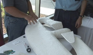
Attach foam to the pre-shaped wing...
Shape the foam overlay... Apply protective coating... Glass
and install the wing-jets... Prepare wing for fiberglass
coating..
**Ram-Implo-Wing Starter Kit:** This
kit now ships with your choice of mounting brackets $399.95
plus s/h $65.00 = Total $464.95
This kit now ships with your choice of
mounting brackets
Custom built wings $865.95 shipping
included... All-new Ram-Implo-wing templates and
construction guide (CD for PC Windows only) now $244.95 ; comes with canard and wing-let
locking tabs plus, New Quick Install Brackets... CD only!
$29.95 Includes several sets of construction plans! CD and
Composite patterns only! $99.95 Includes several sets of
construction plans! Quick Deck Installation Brackets --- End
the hassle of building your own mounting system with these
Quick Set Installation Brackets Comes with two wing brackets,
two deck brackets and two 12-inch struts --- $29.95 plus $9.95
s/h.
**Send check or US money order to:Robert
A. Patterson11405 E. Blue Springs Rd. RT-1 Box 66-AWapanucka
Ok. 73461**
**Ram Wing Kit Builders Association:
**
---
**Testamonials**
From: Mark McDaniel
Date: Wed Nov 3, 2004 5:23 pm
Subject: Mileage
We have a wing on a 78 Lincoln Town Car with a 400 CID engine
that is being driven 109 miles round trip daily to work here
at Firestone. We tweaked it and are getting 56 mpg out of it
at present.The 78 Lincoln Town Car averaged 17.8 mpg before
the wing was placed on it.
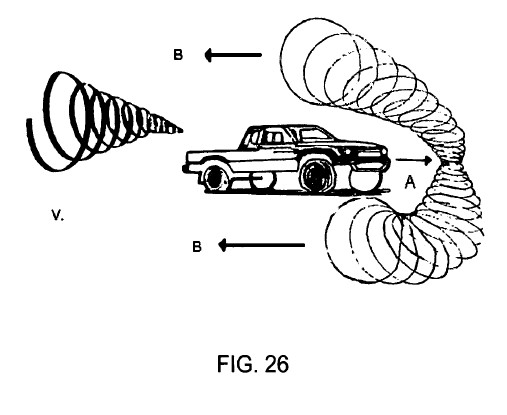
I have another one, different plenum induction design, and it
seems to be working well on my 88 Chrysler Fifth Avenue. My
Chrysler Fifth Avenue (87) with the 318 averaged 20.1 mpg
before the wing went on. This is a different wing design and I
haven't got it tweaked yet, but I'm getting about 46.6 mpg
average at the moment.
We mounted the wing on to the back roof support posts of the
Town Car. This put the trailing edge of the wing about 6
inches out over the back glass and the leading edge of the
wing 12 inches above the roof in a perfectly horizontal plane.
We have found that a very slight upward pitch of the leading
edge of the wing gives the best MPG. We have pitched our wing
to 1 and 1/2 degrees above horizontal to achieve 57 mpg.
Pitching it up more degrades the MPG and pitching down
degrades mpg drastically
Will have more data to relate soon.
Regards,
Lawrence
From: Sal Garza
Date: Thu Nov 4, 2004 5:47 pm
Subject: Re: Mileage
hey Robert,
so far,we are at 30mpg,67-70 mph runs in our Volvo,to and
from the bay area. I am still in process determining optimum
wing height,angle,etc. Of the little 36-inch wing you sent me
for testing, so far we have seen 10mpg over our usual mileage
all best,
s.g.
More Positive Results: ****
---
From: "Robert A. Patterson"
Sent: Wednesday, March 09, 2005 2:29 PM
Subject: [ram\_wing] Re: feedback: air foil = Ram Implosion
Wing Developments?
If a conventional airfoil functioned as envisioned then how
come every street racer complains that his/her time to the
finish line takes longer and their fuel consumption increased
when they added one of these glorified "go fast plastic wings"
to their street rod?
The conventional airfoil was designed to push a jet-stream of
air out form under it and behind the vehicle in an attempt to
brake up eddy currents that trail behind the car as it moves
through the air. The problem with this concept is the
fact that air has a sticky and elastic viscosity that adheres
to the smooth surface of any vehicle and sheds off of the rear
of the vehicle in the form of a rotating vortex. The
suction head of this vortex is the source of the drag and the
vacuum energy that is utilized by race car drivers when they
draft off of the displacement created by the lead car.
In most cases the "go fast plastic wings" that I have seen
are installed on the cars backwards! That is the leading
edge of these wings is the smallest and the trailing edge is
the largest. Ironically with the wing positioned in this
canard (backward) fashion it cannot do anything but cause drag
in the form of an antagonistic vortex. Likewise all
vehicles that present a small leading profile in contrast with
a larger trailing rear-section are 180-degrees out of phase
with natures cyclonic properties.
No animal or egg is birthed with the small end first, its
always the largest end first otherwise its breach, this is
your basic building block, violate this most basic rule of
Bio-engineering and everything you do will be moving
antagonistically backwards (out of phase) through the
environmental spectrum.
Robert A. Patterson
---
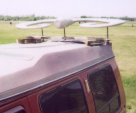
Wingspan 6'6" cord 3'6" 100-lbs. under
went testing mounted to the back of a V-8 Van GVW
5750-lbs. mileage was calculated based on a single gallon of
gas in back to back test runs, pilot 195-lbs.
Resulted in an increases of mileage 2-3-times beyond normal
expectancies, however in an independent test run Aug. 13-th
2003 a Dodge Caravan with a V-6 motor weighing in at GVW
2726 lb.. The driver weighs in at 295 lb. and the copilot
195 lb..
After topping off the tank we drove out
10.1 miles and back the same 10.1 miles for a total of 20.2
miles round trip, at 65-mph with the ac unit on. When we
arrived back at the fueling station we were amazed to find
that we could only squeeze 0.2 tenths of a gallon back into
the tank, we even picked the hose up and tried to pour the
extra gas from the line into the tank but it all ran back
out onto the ground.
20.2 miles @ 0.2 tenths of a gallon =
101-mpg!
A second trip consisted of a 59 mile
round trip but this time we were only able to squeeze 0.1
tenths of a gallon back into the tank.
59 miles @ 0.1 tenths of a gallon =
590-mpg!
[**http://peswiki.com/index.php/Directory:Ram\_Implosion\_Wing:Data**](http://peswiki.com/index.php/Directory:Ram_Implosion_Wing:Data)
**Recommendations**
*More Rigor to Avoid Exaggeration*
Some of the data collected is over far too small of a
sampling size, prone to a large error margin. This is sloppy
science. One cannot go 20 miles and then refill the tank and
expect accurate results.
To get accurate measurements you need to do such things as:
1. Go at least 200 miles.
2. Have a control drive without the device over
the same terrain and same conditions, as close to identical as
possible.
3. Repeat the experiment at least once --
including the control.
4. Use the same gas station, gas, and pump, with
nozzle in same configuration.
The "triple mileage" claim will probably be shown to be an
exaggeration that Robert will be eating.
It is better to under-state than over-state.
The more solid your test procedure, the more people will
believe your results and buy your concept.
Choose a road that is not heavily traveled. Choose a time
when you are least likely to hit delays in traffic.
Drive the path twice without the wing. Keep fastidious record
of your mileage and gas for both round trips. Use the same gas
station and same pump.
Now put the wing on and travel the same road twice; using the
same procedure.
That would be much more convincing data, and that would be on
the border of scientific. Would barely cut "scientific." If
you wanted full scientific rigor, do that times 100.
Do it on another car. Do it with the wing in different
positions. Have it done independently.
Then people will pay attention, big time.
Get test done by e.g. federal aero-labs
*Email Correspondence from J.D., Monday, August 23, 2004.
Posted with permission.*
"We should probably get someone to do a basic simulation on
this.
"It might be worth contacting Dan MacBolen with his Chevy
suburban, to get some data on his results and to have some
local technical people structure and validate his tests. His
claim of 26 mpg in a gasoline powered suburban, is quite good
(and believable, vs. Pattersons claims of 590 mpg!) the
best Ive seen is around 20, at speeds below 55mph.
"I'm sure that the Univ. of OK in Tulsa or the Weapons Center
Engineering team has some scientists that would be glad to
spec and validate Dan's tests
"You should also get someone at one of the federal aero-labs
like NASA AMES in CA,. to do an analysis of the basic 'wing'
design for estimated drag reduction, and potential for
improving overall vehicle efficiency."
*Temperature Effects Tank Volume*
A very important fact the should be taken into consideration
in all these tests and is the temperature of the gasoline.
Gasoline in underground storage tanks is generally cooler
than ambient temperatures and expands after it has been
pumped. That is why you are advised not to fill a tank to the
brim but stop pumping when the pump kicks out automatically.
Otherwise the fuel in the over filled tank will expand and
leak out the overflow.
If you read the calibration certificate usually posted on gas
pumps you will notice that the pumps are calibrated for volume
at a specific temperature.
To be most accurate, the test set-up should include an
accurately calibrated tank; and the temperature of the fuel in
the tank should be rigourously monitored.
(Source: Rob Polley )
---
**Excerpts from:**
**US Patent Application 20050109879**
**Method and Apparatus for Quantum Vortex
Implosion Propulsion and Species**
**( 5-26-2005 )**
**Robert A. PATTERSON**
Robert A. Patterson
Blue Springs Rd Rt-1
Box 66-A
Wapanucka OK 73461 USA
**Abstract ---** System for converting high frequency
quantum electrodynamic radiation energy and at least one atom
through cavity vacuum fluctuations and converting same into a
superconductive electrical implosion propulsion energy from
zero point energy at a frequency that is amenable to
conversion to electrical and implosive propulsion and
superconductive energy extracted within an environment having
a desired voltage and a reversed waveform such that the
emitted energy returns into the system to be recycled. In an
externally winged craft comprising a selectively shaped vacuum
cohesive fuselage and means for providing lift and propulsion
for an aircraft generating an enormous electrostatic vortex
lifting force when energized in conjunction with the quantum
electrodynamic vortex implosion propulsion system and power
plant maximizing fuel efficiencies including the extraction of
usable energy from the vacuum of space. Actually riding on or
in the shock waves verses the brute force disruption of the
environment's equilibrium, as is the case with conventional
modes of transportation or aircraft design.
**BACKGROUND OF THE INVENTION**
[0001] The vacuum of space contains enormous residual
background energy with densities estimated to be on the order
of nuclear energy densities. Zero point energy was predicted
by quantum theory and verified via experimentation and is
known to play a role in large-scale phenomena of interest,
including, aerodynamic and/or fluid mechanics, renewable
superconductive energy, holographic optical communication
technologies. Linear spectral filtering which offers unique
potential for future high-bandwidth communication systems.
Inhibition of spontaneous emission, the generation of
short-range attractive forces (e.g., the Casimir force.)
Topics of interest range from space-flight applications to
fundamental issues of renewable energy sources to cavity
Quantum Electrodynamics (QED) laboratory attempts extracting
useful energy from vacuum fluctuations thereby verifying
environmental energy may indeed be extracted for practical
use.
[0002] Selectively engineered shapes may convey energy via
high and low-pressure differentials with emphasis on
convergence zones, i.e., when high pressure air flips from
underneath a wings surface over onto the upper section of the
wing where low pressures abound whereby a vortex is formed via
the high and low pressure convergence of two opposing forces
FIGS. 17, 18, 19, 20, 21, and 22. [ &c &c ]
**[0009] 1. Field of the Invention**
[ ... ]
[0010] This invention relates to improvements in aircraft
incorporating vortex chamber swirl-vane-designs, mixing of
radial and tangential flows and more particularly but not by
way of limitation, to means for providing lift and propulsion
for aircraft, extracting usable energy from the environment
through vortex, action, air passing through an hyperbolic
chamber, vortex convergence and swirl zone. Said suction-head
or vortex flow gives rise to higher-pressure differential
gradients of either-or high or low pressures forming a vacuum
so that the pressure difference provides lift and propulsion
for the aircraft.
[0011] From the mechanical and geometrical points of view,
the invention or aircraft designed and/or otherwise built as a
usual or conventional airplane-glider will give rise to long
running flight times, limited to landing only by the pilots
needs, otherwise describing the human condition. By virtue of
the invention's selective shape and interaction with nature
said invention becomes a no moving part motor.
[0012] From the electronic point of view, the aforementioned
invention may be thought of as a no moving part motor,
analogized as an electric motor wherein the invention becomes
the stator and thus the air becomes the rotor thereby meeting
the definition and criteria consistent with the description of
a motor.
**[0013] 2. Description of the Prior Art**
[ ... ]
[0028] As set forth within the elements of Aerofoil and
Airscrew theory an aircraft's wing is designed with a plane of
symmetry passing through its mid-point of span, and the
direction of relative motion to the plane of resultant action
in said plane.
[0029] Generally speaking, a common practice is to shape the
wings of an aircraft so that the velocity of air streaming
over the top or upper most surface of each wing is greater
than the velocity of air streaming over the bottom or lower
most or under surface of the wing. This velocity differential
achieved by the contour of the wing, results in a pressure
differential across the wing so that a net force, lift, is
exerted on the wing to support the aircraft in flight.
[0030] Chord-line of an airfoil is defined as the line
joining the centers of curvature for the leading and trailing
edges and the projection of the airfoil section on this line
is defined as the chord length. An airfoil's angle of
incidence is defined as the angle between the chord and the
direction of motion relative to the fluid through which the
body is moving. An airfoil's center of pressure is defined as
the point in which the line of action of the resultant force
intersects the chord. Said resultant force is resolved into
two components, lift, at right angles to the direction of
motion and drag parallel to the direction of the craft
although opposing the forward motion of the craft.
[0031] A common design flaw inherent within all aircraft of
usual design is the aircraft's own geometrical shape design.
That is any wing that deviates form the one hundred present
efficient elliptical wing shape assumed 100% efficient for
purpose of comparison. Wherein the shock wave of parasitic
drag is considered unavoidable and a price requiring payment
in excessive fuel consumption wrought by incorrectly designed
cantilevered wings disposed out from the aircraft's body
ending with tapered wing tips.
[0032] Thereby decreasing the relative efficiencies of basic
wing plane-forms with each wing inductively inducing parasitic
drag according to the wings own geometrical deviation from the
perfect ellipsoidal plane-form.
[0033] Experimentation has greatly improved aircraft design,
achieving greater flight performance as well as economic
efficiencies of operation and construction methods thereof,
yet to-date many problems exist within the industry.
[0034] Since the primary shock waves created by an airplane's
wings cannot be avoided, the key to solving sonic problems
clearly lies in wing design. Shock waves cannot be prevented
but their effects can be reduced by several means making the
wings thinner, sharper leading edges; shorter and wider
designs sweeping them forward taking advantage of the shock
wave or shaping the wing rearward in avoidance of said shock
wave.
[0035] Unfortunately, the more tapered or swept back the wing
becomes the more adversely the wing becomes affected by
parasitic shock waves sapping the aircraft's momentum and
consuming excessive amounts of fuel conversely an ellipsoidal
shaped wing is 100% co-efficient.
[0036] Several combinations of these principles have been
built into all modern high-speed aircraft. But all designs are
at best compromises; some high-speed capabilities have to be
sacrificed to enable the aircraft to be operative at low
speeds e.g., take off and landing. This difficulty has been
tackled with variable-sweep wings combining the best of both
worlds for high-speed operation the wings can be angled in
mid-flight, a drawback of the system is the complex equipment
needed to move the wings.
[0037] In order to reduce supersonic wave drag further
engineers need to study the wings and fuselage as a unit
presented to the on-rushing air. Interestingly they found it
important that the areas of consecutive cross-section of the
plane, increasing from the nose and decreasing towards the
tail, should add up to the smallest possible curve. Under this
theory, called the "area rule" the perfect shape would be an
egg but the necessity for wings forces compromise. Therefore
results will be significant not only for the performance but
also for the look of supersonic aircraft and beyond.
[0038] Paying particular attention to a design theory called
the "compression lift rule" The basic idea here is that
surfaces can be so arranged that shock waves will actually
reinforce one another to provide lift, as in a planning
speedboat or a rock when skipped across a pool of water.
Because shock waves so severely affect an airplane's
stability, the greatest problem for a pilot at the sound
barrier is the changing control characteristics. A wing has a
slowly moving layer of air called the "boundary layer" that
clings to its surface.
[0039] Near Mach 1 shock waves can interact with the boundary
layer to distort the airflow so that lift may be impaired and
control surfaces rendered ineffectual. This disturbance also
adds to the turbulent wake, which is created by any
conventional wing, whatever its speed. Therefore "wing-shape"
and "surface-texture" is obviously important to the strategic
control of airflow.
[ ... ]
[0063] Vortex Chambers
[0064] C. D. Pengelley published a simplified analysis of
two-dimensional vortex fields in 1956. The calculations gave
dimensionless pressure and temperature charts and included a
numerical example for the two-dimensional vortex flow field.
The purpose of the input element of a vortex pressure
amplifier is to introduce swirl into the vortex chamber as a
function of pressure input. As described above, the input
element may be widely different for the various vortex
devices: a single tangential orifice in vortex diodes,
multiple nozzles located symmetrically to produce the balanced
flow required in the Ranque-Hilsch Tube and Swirl Atomizers,
and porous coupling elements in vortex inertial sensors to
impart the small inertial rotation to the incoming fluid. In
vortex valves and pressure amplifiers, the function of the
input element includes the noise free mixing of a radial
supply flow stream with the tangential control input.
[0065] The simplest design is the two port configuration,
where the supply flow enters through a single tangential port
mixing of the tangential momentum is accomplished efficiently
and uniformly in the annular zone prior to entry into the
vortex chamber as long as the annular zone allows free mixing
of the control inputs, linear addition and subtraction of any
number of pressure inputs is possible in the input elements of
a vortex pressure amplifier.
[0066] In general, three basic rotational flow-fields may be
encountered in a vortex chamber:
[0067] 1. The solid body rotation or forced vortex flow
occurs under high viscous coupling. At extreme tangential
velocities the apparent viscosity in gases becomes large;
values of the order of a thousand times the normal viscosity
have been estimated in experimental reports on the
Ranque-Hilsch Tube.
[0068] 2. The free vortex rotation is defined by constant
angular momentum. This mode of rotation may be observed in
bodies of gases rotating at comparatively low velocities, when
the effective viscosity becomes negligible.
[0069] 3. Constant tangential velocity is a unique
intermediate velocity distribution between the free vortex and
forced vortex rotation. Tangential velocity profiles may be
described for all conditions by simple exponential equations.
[0070] For specific velocity distributions, the value of n
may be defined:
[0071] =-1 for free vortex velocity distribution
[0072] =0 for constant velocity distribution
[0073] =+1 for forced vortex velocity distribution
[0074] Experimental results describing early development of
vortex devices may be found in several of the referenced
publications. The 1964 Proceedings of the Fluid Amplifier
Symposium at the Harry Diamond Laboratories contain
experimental results obtained with vortex fluid amplification
[Vortex Physics: Studies of High Temperature Superconductors
(Studies of High Temperature Superconductors, Vol. 42) by A.
V. Narlikar Publisher: Nova Science Publishers, Inc. (May
2002) ISBN: 159033342X; Implosion The Secret of Viktor
Schauberger, Complied by Tom Brown, Translated from German by
Jorge Resines; Viktor Schauberger and his discoveries
Implosion vs. Explosion by Leopold Brandstatter; Implosion At
First Hand from the 1977 July-Aug Journal of Borderland
Research, by Riley Crabb; Viktor Schauberger and his work from
the 1979 May-June Journal of Borderland Research by Albert
Zock; R. Hilsch, The Use of the expansion of gases in a
centrifugal field as a cooling process, review of scientific
instruments XYI11, No. 2, February 1947, 108].
**OBJECTS AND ADVANTAGES**
[0075] It is another object of the present invention to
provide a system for converting zero point electromagnetic
radiation energy to electrical energy [ &c., &c ]
[ ... ]
[0086] An object of the present invention is to provide but
not by way of limitations, an aircraft with a propulsion means
for forming a rearward directed air stream as well as an
improved embodiment comprising an implosive suction-head so as
to propel the aircraft simultaneously. In other words the push
and the pull energy contained within the elasticity of the air
stream are combined whereby useful work is preformed.
[0087] Another object of the present invention is to enable
sustained and accelerated flight duration, too solve these
problems without excessive fuel consumption, over heating of
the fuselage e.g., applying ceramic materials to the exterior
hull section of the craft and eliminating excessive drag
common to conventional aircraft design another object is to
provide aircraft of the design embodied here with a means of
cooling itself.
[0088] Yet a further object of the present invention is to
provide an enhanced flexibility in aircraft design.
[0089] Still another object of the present invention is to
provide an aircraft with either a low or a high flight speed
capability while reducing frictional losses. Another object of
the present invention is to provide variable flight
characteristics in an aircraft.
[0090] An additional object of the present invention is to
reverse parasitic drag into a beneficial energy source doing
useful work otherwise caused by the incorrect application of
geometrical structures having been applied by conventional
designers whereby the present invention overcomes this defect
through the proper selection of a functional shape.
[0091] Other objects, methods, advantages and features of the
present invention will become clear from the following
detailed description of the preferred embodiments of the
invention when read in conjunction with the lab report a
species embodiment and drawings and in conjunction with the
implosion propulsion system as well as append claims.
**BRIEF DESCRIPTION OF THE DRAWINGS**
[ ]
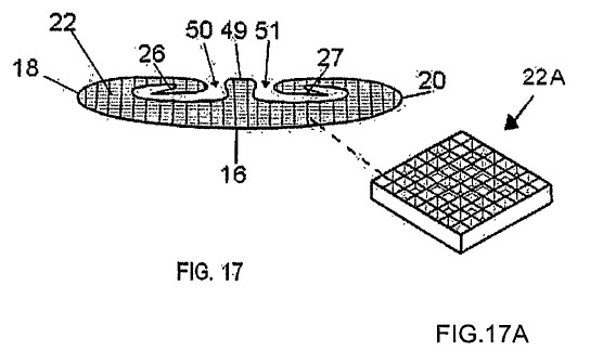
[0108] FIG. 17 is an overhead view of an aircraft embodying
the invention and particularly Illustrates the hyperbolic
shaped horizontal vortex flow chambers the swirl vanes and
eddy current diffusion cells FIG. 17A [22A] there on the
surface of the wing and a means for controlling the vortex
suction-heads illustrating an operational mode thereof.
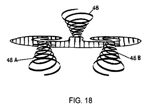
[0109] FIG. 18 is an overhead view depicting the vortex
formations [48] [48A] and [48B] of the aircraft shown in FIG.
17.
[0110] FIG. 19 is a rear elevation-al view of the aircraft
shown in FIG. 17.
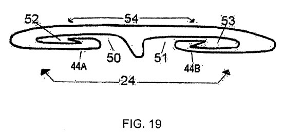
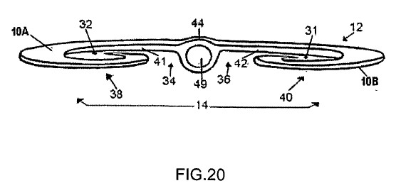
[0111] FIG. 20 is a front elevation-al view or the aircraft
in FIG. 17.
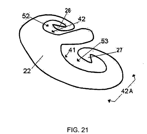
[0112] FIG. 21 is a 45-degree angle view showing (S) or
scallop pattern or pinched in shape (optional) of the fuselage
and vortex chamber of an aircraft embodying the invention.
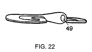
[0113] FIG. 22 is a side elevation-al view of one fuselage
shape embodying the invention also showing a hyperbolic
impression there in the nose cone of the aircraft a wave
reversal unit, which is an impression, or void of a
predetermined shape and depth embodying the invention.
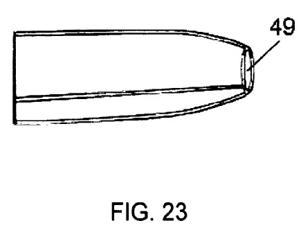
[0114] FIG. 23 is a side elevation-al view of the preferred
fuselage shape and configuration detailing a hyperbolic
impression there in the nose cone of the aircraft a wave
reversal unit, which is an impression, or void of a
predetermined shape and depth embodying the invention.
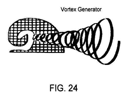
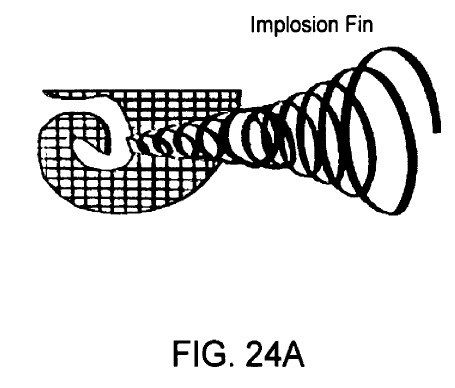
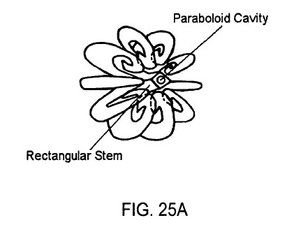
[0115] FIGS. 24, 24A, 25, 25A and 26 depict species
embodiments of the invention herein disclosed via lab reports.

**DETAILED DESCRIPTION OF THE PREFERRED EMBODIMENTS**
[ . ]
[0145] In the embodiment of FIGS. 17 and 17A [22A] located on
all surfaces are two-dimensional waffle-type patterns
dispersed on the surface of the wing, that is a
quadratic-residue diffuser, a two-dimensional cell that
diffuses acoustical energy and (preferably eddies currents) in
both the horizontal and vertical planes for all angles of
incidence thus forming a vacuum state many times higher in
degree then the surrounding environment [The Master Hand-Book
Of Acoustics 3-RD Edition "Everest" Diffusion In Three
Dimensions pp. 256-262].
[0146] FIG. 17 is a diagrammatic representation of one
specific embodiment of a component 1 in accordance with the
invention generally indicates an internal wing there disposed
within a horizontal vortex flow chamber aircraft comprising a
flying-wing fuselage FIG. 20 [12] having a forward end FIG. 17
a rear end [16], a first side [18], a second side [20], an
upper surface FIG. 21 and a lower surface FIG. 19 [24], the
connotations top and bottom being used to generally indicate
the uppermost and lowermost surface of the aircraft FIG. 20
[10A] and [10B] when the aircraft is in substantially level
flight, or in a stationary mode. A control surface [26] and
[27] are provided at the aircraft's vortex-swirl-vane FIG. 17
and left and right hand control surfaces [28] and [30] are
disposed at the front of the craft on opposite sides [28] and
[30] and are movable simultaneously, but in opposite
directions, to produce a rolling movement about the
longitudinal axis of the aircraft [1] and may therefore be
rendered optional and may be removed from the craft when
controlled or steered electronically (not shown) verses
mechanically.
[0147] FIG. 18 is an overhead view depicting the vortex
formations of the aircraft shown in FIGS. 17-22 whereby
atmospheric vortex action sets into motion a cooling effect
which is leveraged from the direct action of the atmospheric
harmonics produced by said rotary vortex said vortex rotary
which sets up a thermal acoustic effect or thermoacoustic
alternative vortex refrigeration powered by standing sound
waves caused by a temperature gradient formed there in the
convergence zone of FIGS. 17 and 18 there forming vortex
suction-heads to occur which may set up a sound wave causing
an interaction between the atmosphere and vortex chamber to
harmonically sing or whistle this new refrigeration technique
is decidedly low-tech however practical for producing ambient
temperature superconductive devices a predetermined frequency
comprising a standing wave note at just the right frequency to
set up a standing wave of sound causing environmental cooling
via vortex possessing a predetermined atmospheric pressure the
sound waves cause the atmospheric gas to go through cycles of
compression and expansion which is a key factor to acoustic
cooling because gas heats up a bit when compressed and cools
as it expands when a compression phase of the sound wave comes
along the gas molecules of the atmosphere collide within said
vortex and a vacuum cohesive vehicle VCV hull structure from
which it radiates away then the gas expands and cools further
than it would otherwise and some of its heat has been drawn
off the process a progressive cooling which can be exploited
for refrigeration the result is a refrigerant system that uses
no ozone depleting CFCs and has only one moving part the
environment it is the direct manipulation of said environment
that conveys the craft along with its relative motion the only
issue keeping the acoustic refrigeration system from producing
an ambient temperature super conductor is a lack of
interdisciplinary talent.
[0148] The people who apply cryogenics do not apply acoustics
maybe this is the reason why there has been so little
advancement in the art of ambient temperature super
connectivity and when current is applied to the ceramic
composition of said VCV aircraft standing sound waves get
compressed and heat up nearby atmospheric molecules these
atmospheric molecules collide and transfer some of their heat
and cool down a bit after expanding the atmospheric molecules
end up with less heat energy and are cooler than when they
began the cycle.
[0149] Researchers have already built a number of working
acoustic coolers some capable of producing temperatures of
around minus 100 degrees Fahrenheit and have even been used
aboard the space shuttle because they have fewer moving parts
than conventional cooling systems acoustic coolers may well be
suited to applications on satellites and space vehicles and
even for ambient temperature super conductors where efficient
maintenance free cooling is crucial.
[0150] An engine or suitable quantum electro-dynamic power
plant as shown in FIGS. 4 and 6 mounted in the forward end
FIG. 20 of the aircraft [1] in any suitable manner as is well
known and the power plant may also be any type which produces
a rearward air stream and/or vortex flow or suction-head so as
to provide thrust for the aircraft [1]. Of course, suitable
conventional landing gear (not shown) may be provided for the
aircraft which my therefore be rendered optional and may be
removed from the craft when propelled via quantum electro
dynamic implosion propulsion FIGS. 4 and 6 verses mechanically
and/or conventionally and/or radio or electronic steering
control devices (not shown) are provided for guidance and
optionally the actuation of the control surfaces in the usual
or well-known manner may also be omitted thereby opting for
electronic steering (not shown).
[0151] Horizontal hyperbolic vortex chambers FIG. 21 [52] and
[53] are provided in the airfoil or fuselage FIG. 20 [12] and
[44] of craft [10] with the forward end of the input elements
[34] and [36] provided with openings [34A] and [36B] disposed
on opposite sides of the fuselage [44] and on opposite sides
of the power plant or engine shown in FIGS. 4 and 6 of VCV
FIGS. 17, 18, 19, 20, 21 and 22 craft [10]. In addition, the
vortex chambers FIG. 21 [52] and [53] are provided with
openings FIG. 20 [31], [32], [38], and [40] disposed on the
opposite sides of the fuselage [44] and disposed on opposite
sides of the flying wing [12] and on opposite sides of the
engine shown in FIGS. 4 and 6. The upper most section [42]
FIG. 21 of the chambers [52] and [53] depicted a substantially
ellipsoidal egg-shaped configuration and the ports or openings
[34], [36], [38] and [40] are separated by a centrally
disposed fuselage means FIG. 20 [44] and swirl-vane system
FIG. 17 [26] and [27].
[0152] The upper surface of the swirl-vane [26] and [27]
provides a floor or bottom FIG. 20 [10B] for a passageway [38]
and [40] that communicates between the hyperbolic chambers
FIG. 21 [52] and [53] and the openings FIG. 20 [34A] and [36B]
and that of [34], [36], [38], and [40] and the upper contour
FIG. 21 [42] of the main wing.
[0153] The lower surface FIG. 19 of the vortex swirl-vane
means [44A] and [44B] provides a convergence zone or surface
at the hyperbolic chambers [52] and [53] at the input elements
[38] and [40] and the appropriate configuration of the
hyperbolic chamber [52] and [53] and the substantially
hyperbolic egg-shaped configuration of the surface FIGS. 17,
19, and 20 [34], [34A], [36], [36B], [41], [42], [50], and
[51] converge to provide a reduced area or throat [50] and
[51] shown in FIGS. 17, 19, and 20 an input to said hyperbolic
chamber [52] and [53] disposed aft of the openings [34],
[34A][36], [36B], [50], and [51].
[0154] As the air stream moves through the ports or openings
[34A] and [36B] the velocity thereof is increased by the
configuration of the forward section of the hyperbolic chamber
and vortex swirl-vane, this increased velocity at the exit of
the throat [41] and [42] creates a suction at the converging
passageway [31], [32], [34A], [36B], [38], [40], [52], and
[53] for drawing in ambient air through the ports [34], [36],
[38], and [40]. The combined air-streams then move rearward
through the hyperbolic horizontal vortex flow chambers [52]
and [53] there flowing across the upper surface of the main
wing turning vane whereby the rearward jet-stream of moving
air is further accelerated and turned down for discharge at
the aft-end [16] of the wing thereof.
[0155] At least two movable flap means [28] and [30] (not
shown) are hinged or secured in any well-known manner at the
front open end [14] of the vortex chambers that are
selectively movable by the operator of the aircraft FIG. 17
[28] and [30] and secured substantially in the center of the
hyperbolic chamber in spaced relation with respect to each
other and movable simultaneously and in the same direction to
provide a vertical force along the leading edge of the
aircraft FIG. 17 thus changing the attitude of the craft, as
is well known and may therefore be omitted when electronically
steered.
[0156] Referring now more particularly to FIG. 19 a rear
elevation-al view of the under portions of the hyperbolic
chambers [52] and [53] view thereof. The cross sectional
configuration of the hyperbolic chambers [52] and [53] at the
leading edge opening FIG. 20 [34], [36], [38], and [40] are
substantially elliptical shown at [52] and [53] in FIGS. 19
and 21. The cross sectional configuration of the vortex
chambers [52] and [53] becomes substantially elliptical as the
vortex chamber progresses in the direction of the throat or
input elements FIG. 20 [34], [36]. FIG. 19 [50], and [51] the
elliptical configuration being shown FIG. 19 [52] and [53].
[0157] The cross sectional configuration of the throat or
input elements [50] and [51] as shown in FIG. 19 may be
configured substantially pinched-in rectangular hyperbolic or
other suitable shapes an example may be curved in. This
graduation of the configuration of the vortex chambers [52]
and [53] controls the movement of the air stream between the
openings FIG. 20 [34], [36], [41], and [42] and the throat
FIG. 19 [50] and [51] whereby the speed of the air stream is
substantially squeezed as it enters the throat as herein set
forth.
[0158] The aircraft shown in FIGS. 17-22 are provided with a
pair of oppositely disposed inwardly extending relatively
small wings swirl-vanes [26] and [27] likewise the aircraft
shown in FIGS. 17-22 are provided with external wings there
disposed within horizontal vortex chambers. The lifting force
in the craft is attained entirely by the main wing section in
conjunction with the internal hyperbolic vortex amplification
chamber and swirl-vane system FIG. 17 as hereinbefore
described. The novel aircraft design lends itself as desired
to an efficient glider or single or multiple engine design or
a quantum electro dynamic implosion propulsion system as shown
there in FIGS. 4 and 6.
[0159] The aircraft as shown herein, may be provided with at
least two engines (not shown) or powered by a quantum electro
dynamic implosion propulsion system as desired and shown in
FIGS. 4 and 6 In addition, the novel aircraft design may be
utilized in the construction of large transport or cargo
aircraft or spacecraft with equal efficiency and economy of
operation and construction.
[0160] The lift for the aircraft [10] is generated by the
action of air moving over the main wing section whereby the
air is accelerated through the hyperbolic vortex chambers [52]
and [53]. The swirl-vane directs the airflow from the
underside and forward input elements [38] and [40] to the
rearward outlet [16] for discharge at the rear of the craft.
The movement of the air stream moving over the contoured
section of the floor or upper most surface [12] creates a
pressure and velocity change in the air stream. The
configuration of the vortex chamber is such that a lower
pressure is created on the roof or undermost surface [12] of
the main wing than is created on the floor or lowermost
surface [24] of the wing. The net difference in the pressure
change results in an upward force or lift. The shape of the
vortex swirl-vane and/or the configuration of the inner
periphery of the hyperbolic chamber and the amount of air that
moves through said vortex amplification chamber and across the
main wing structure control this force.
[0161] The configuration of the vortex swirl is altered by
the mechanical control mechanism [28] and [30] which may be
deleted when electronically steered (not shown) which not only
varies the configuration or contour of the vortex swirl FIG.
18 [48A] and [48B] of the hyperbolic chambers [52] and [53]
and upper surface [10A] of the chamber. As the airspeed is
increased through the vortex chambers [52] and [53], and FIGS.
20 [22], [23], [49] a wave reversal chamber composed of a
predetermined size and depth there disposed within the nose
cone section of the craft said wave reversal unit actually
turns the air-stream encountered by the craft away from the
aircraft FIGS. 20, 22 and 23 forming a vortex or suction-head
FIG. 18 [48], [48A], [48B] requiring less fuel to be expended
as opposed to conventional craft that are tapered to a point
which actually turn the air stream back antagonistically
toward the craft whereby more conventional fuels are required
to generate the desired flight parameters Conversely, as the
airspeed is decreased, more fuel is required to maintain the
usual aircraft's required vertical force or lift.
[0162] Of course the chamber size must be sufficiently great
so as to permit the airflow through the contoured section of
the vortex chamber without undue restriction of the movement
of the air stream with the contoured section configured with
the greatest or highest curvature for the contoured section of
wing FIG. 21 [22]. Similarly, the size of the vortex chamber
cannot be so large that the air stream is allowed to pass
through the chambers [38] and [40] without being properly
influenced by the contoured sections.
[0163] The actual particulars of the vortex-chamber its shape
and size are dependent on the considerations controlling the
detailed design of the aircraft for its anticipated mission
requirements. The operation of the vortex chamber and the
contained contoured section FIG. 21 [42] provide the
characteristics necessary to fulfill the fundamental
requirements for producing a lifting and/or propulsion force
for the aircraft.
[0164] It will be readily apparent from the drawings that the
plane of the input elements [34] and [36] of the vortex
chambers [52] and [53] are angularity disposed with respect to
the direction of the incoming airflow. The vortex chamber
inputs [34] and [36] are sensitive to this angular alignment,
as is well known in the nature of input elements in general.
The larger the angular alignment the larger the airflow
properties as the air stream enters the vortex chambers [52]
and [53] and begins its movement through said chamber. There
are some small practical limits to this consideration, and
this is the reason for the incorporation of the usual
pitch-attitude control that is much like that of a
conventional aircraft's major control device.
[0165] The flaps provide the pitch control [28] and [30] (not
shown) and a swept-up or a turned up tail section (not shown)
usual to flying wings aft section [16]. When these flaps are
operated in conjunction with each other simultaneously and in
the same direction, a vertical force is produced along the
trailing edge of the aircraft [16], thus changing the attitude
of the craft. Of course this attitude change may be computer
controlled or otherwise monitored by the pilot in order to
adjust the alignment of the aircraft with the airflow.
[0166] Similarly, the pilot of the craft may maintain the
directional control of the aircraft [10]. The directional
alignment of the control surfaces [28] and [30] their
directional alignment play an important role in the efficiency
of the aircraft's stability and is fundamental to the
maneuvering of the craft to a desired position or place. The
horizontal jet-stream turned-up vane or tail section usual to
flying wing aircraft (not shown) and the swirl-vane flaps [28]
and [30] provide the necessary force to produce a rolling
movement or level flight plan of the craft when flow by usual
methods.
[0167] The rolling control of the craft is accomplished by
the utilization of the flaps [28] and [30] (not shown). It is
preferable that the flaps [28] and [30] (not shown) be
arranged in co-operating left and right hand pairs, with one
of each pair being disposed on each vortex swirl-vane. The
flaps or control surfaces of the right hand pair may be moved
together, and the flaps of the left hand pair may be similarly
moved together but in opposite directions with respect to the
movement of the right hand pair.
[0168] This split movement feature produces a rolling
movement about the longitudinal axis of the aircraft and
modulation of the operation of these control surfaces will
enable the pilot to bank, roll, and otherwise maneuver the
craft in much the manner as a conventional aircraft. Of
course, as herein-before set forth, all of the control vanes
and/or surfaces are operably connected in any suitable or
well-known manner including radio control or electronically
steered (not shown) for actuation by the pilot of the craft
optionally all moving parts including flaps of any suitable
type that are capable of steering said craft may be deleted or
otherwise removed the equation when electronic steering is
chosen (not shown).
[0169] The function of the vortex chamber [52] and [53] are
based on the amount of air moving through the input element
section [34], [34A], [36] [36B], [38] and [40] and swirled by
the vortex swirl-vane [26] and [27] thereof to produce the
desired vertical and linear force for the particular flight
conditions of the aircraft [10]. The movement of the
air-stream through the vortex chamber [52] and [53] is the
result of energy that is supplied to the air stream by the
aircraft and its systems. This energy is supplied by moving
the craft through the air ramming or by pumping the air
through the vortex chambers by some mechanical means. When the
forward movement or velocity of the aircraft i.e. produces the
entire airflow ram induced, the performance of the craft will
not be dependent solely upon the power available to move the
craft through the air. When the air stream is ram induced FIG.
21 through the vortex chambers [52] and [53], the performance
of the vortex chamber and the craft are greatly enhanced.
[0170] Similarly, pumping of the air may be accomplished in
any suitable manner, such as by utilization of an impeller
fan, ionization, quantum electro dynamic implosion propulsion
system or the like, as shown in FIGS. 4 and 6 which may be
disposed at either the intake or outlet end of the vortex
chamber. Under these conditions, more energy is usually
available when the fan is utilized to produce both a suction
force and too produce a pressure simultaneously. In other
words, it may be expedient to place the Impeller fan at the
outlet of the vortex chamber rather then the inlet thereof.
[0171] Pumping of the air FIG. 21 through the vortex chambers
[52] and [53] may also be accomplished by pumping a percentage
of the air stream through the input elements [50] and [51] at
higher pressure and entraining the remaining air by viscous
action, which is the principle of a jet pump. In the aircraft
this is accomplished by diverting the air from the power plant
or engine (not shown) of the craft into the input elements
FIG. 20 [34] and [36] of the vortex chambers FIG. 21 [52] and
[53] and discharge the air stream through the outputs thereof.
[0172] The air stream entering the input elements [34] and
[36] moves to the throat or pinched pipe area FIGS. 17 and 3
[50] and [51] where the velocity of the air stream is
increased and as the air stream exits through the pinched pipe
or throat area [50] and [51], ambient air is pulled into the
vortex chambers [52] and [53] through the input elements [38],
[40], [50], and [51].
[0173] The generation of a lifting force by flowing air
through an internal passage, FIG. 21 such as the vortex
chambers [52] and [53], are dependent upon the shaping of the
passageway itself, and the utilization of the contoured
chambered portion [42A] is much like the upper surface of an
airfoil configuration wherein a velocity change is created in
the air as it passes over the main wing having passed through
the vortex chamber. Since the shaping is primarily contained
within the wing [10] of the vortex chambers [52] and [53], the
largest velocity change occurs along the floor [12] and a
lesser velocity change occurs along the under surface of the
wing FIG. 19 [24] of the vortex chambers [52] and 53.
[0174] Proportional to the changes in velocity along the
length of the vortex chambers FIG. 21 [52] and [53], the
pressure acting on the floor [10B] is increased and the roof
[10A] is reduced.
[0175] The pressure along the floor or upper surface of the
wing [10A] is reduced more than the pressure along the roof
[10B], thereby creating a pressure differential between the
two surfaces. This pressure differential acts on the surface
area of the contoured portion of the wing FIG. 21, [22] and
[42A] to create a vertical force in much the same manner, as
does an external wing structure.
[0176] The relationship between the pressure change in the
air stream passing through the passageway or vortex chambers
[52] and [53] and the shape of the inner periphery [41] and
[42] of said vortex generators [26] and [27] are directly
related to the co-ordinate dimensions of the contour size and
shape, and this relationship is well defined and computable by
conventional and well known methods. In the flying of an
aircraft, lift has always been conventionally controllable by
changes in the angle of attack, coordinated with an airspeed
or change in airspeed of the craft.
[0177] In the novel invention a ram implosion wing aircraft
[10] the requirements are to produce a change in lift by
changing the coordinate dimensions of the vortex generators or
swirl-vanes [26] and [27] and their control surfaces [28] and
[30] for the given airspeed or change in airspeed, and this is
accomplished by the actuation of the control device (not
shown). The effects of pitch attitude are the same in the
aircraft [10] as in conventional external wing aircraft and
are utilized in the production of lift in the craft [10]
except when the optional control means (not shown) is by
electronic steering said mechanical actuation my be removed
from the craft.
[0178] The mathematics and physics surrounding the
calculations of the velocity ratios at each horizontal vortex
chamber are represented by the Navier-Stokes equations for an
incompressible fluid. Because the domain of flow is unbounded
and vortex rings are known to diffuse and translate, the
equations are expressed in translating, expanding spherical
co-ordinate airflow. As an example of the effects of the
contour of the floor [42A] on the velocity of the air stream
passing over it, a comparison between a low curvature surfaces
may be made.
[0179] As herein-before set forth the configuration or
contour of the inner periphery of the vortex swirl chamber
[52] and [53] is controlled by contour means thereof [52] and
[53], and as the airspeed is increased through the vortex
chamber, less expenditure of conventional fuels are necessary
to generate the desired vertical force or lift. Conversely, as
the airspeed is decreased, the greater the fuel expenditures
required to maintain the required vertical force or lift for
the aircraft due primarily to the decrees in ram inductive
forces.
[0180] From the foregoing it will be apparent that the
present invention provides a novel aircraft utilizing an
internal wing concept there disposed within an externally
mounted wing wherein an internal hyperbolic vortex swirl
chamber extends through the fuselage of the aircraft and is
provided with inlet means at the forward end and passing
through the upper and lower section of the wing thereof and
outlet means at the top surface and aft end of the wing
thereof. The air stream passing through the vortex chamber
creates an upward force or lift for the craft and control
vanes are provided for achieving the usual or desired
operational characteristics for the craft generally similar to
more conventional external wing aircraft and optionally said
control vanes may be disposed of in favor of electronic
steering (not shown).
[0181] The novel aircraft concept lends itself to application
for single engine, multi-engine craft (not shown) or
super-conductive quantum electrodynamic implosion systems as
shown in FIGS. 4 and 6 high-speed operational craft, large
transport and or cargo craft, spacecraft, or substantially any
other desired in-flight operational requirements.
**SUMMARY OF THE INVENTION**
[ ]
[0254] The use of vortex flow through a horizontal orifice,
chamber or duct formed through the fuselage of an aircraft, as
in a wing mounted externally of the fuselage, results in a
number of benefits. A vortex generating lift system will
generally result in a more compact aircraft or wing than can
be constructed using conventional wings and the use of a
hyperbolic convergence zone offers flexibility in the design
of aircraft to meet varying purposes.
[0255] Since the shape of the exterior of an aircraft having
a vortex generating lift system and hyperbolic convergence
zone can remain fixed while the profile of the swirl-vane is
changed, such change can be used to vary the performance
characteristics of the aircraft so that the aircraft designer
is given a design variation capability that will generally not
be available where external wings only are used to lift the
aircraft. That is, changes in performance can be accomplished
by shaping structural members that provide the longitudinal
camber of the floor and the effect of such shaping can be
determined independently of other factors involved in the
overall interaction of the aircraft with the air through which
the aircraft will move.
[0256] Moreover, since the swirl-vane is within the fuselage
of the main wing, an aircraft constructed in accordance with
the present invention offers the capability of providing
mechanisms for shaping the swirl-vanes or vortex generators in
flight without affecting the structural integrity of the
aircraft as might be the case were shaping attempted in a wing
extending in cantilever fashion from the fuselage
independently. In addition, the formation of lifting surfaces
within said horizontal vortex flow permits a direct
utilization for vacuum-cohesion purposes of air streams
produced by vortex rotations, (normally thought of as
parasitic drag induced by incorrect geometrical aircraft
structures) now used to propel an aircraft so as to provide
lift from the forward Ram-induction or forced vortex motion of
the aircraft through the air. With lifting surfaces formed in
an open horizontal vortex flow chamber, such streams can be
diverted to provide lift and propulsion so that the aircraft
can be flown at lower or higher speeds than would generally be
the case for comparable aircraft having external wings alone,
primarily due to the natural cooling effects and energy
amplification caused by selective geometrical shaping of the
wings.
[0257] This section below describes a species and alternative
applications and embodiments as used in the present invention
as a vortex generator FIG. 24 and also showing a vortex
formation as used in the innovation; for use on planes,
trains, boats, submersibles and vehicles of any type said
invention is also applicable for use on surfboards as an
implosion fin FIG. 24 and is also well suited for use as a fan
blade comprising radial flow fan blades FIG. 25. Primarily the
only aspect of the invention that changes is the application
for which said invention is used however the overall geometric
shape and function remain unchanged no matter if the invention
is used as a wing a fan-blade a surfboard fin a spoiler a wing
or the selective shape of a superconductor these are just
applications to which the method or technology apply and the
general shape and function do not change as described herein
the article below as is above and is well known to persons in
the art.
[0258] This section below relates to the present invention in
a lab report and as a species embodiment configuring the
present invention into a surfboard fin FIG. 8a and also
showing a vortex formation as used in the innovation.
[0259] Conception and build date Feb. 2, 1997 4:36 PM Calif.
I Robert A. Patterson (R.A.P.) did conceptualize and build a
prototype consisting of three scaled down implosive vortex
fins and one surfboard for use on surfboards by forming a
pattern with paper board stock and hand laminating said
pattern with glass cloth and resin I did build three implosion
fins and mounted each to a scale sized surfboard I did test
the design in a rectangular wave tank and through visual
inspection and detection I discovered that the usually
V-shaped antagonistic and parasitic wave front which adversely
affects designs of usual configuration had effectively been
reversed and eliminated and was now imploding via suction-head
actually pulling in a forward manner on the entire surfboard
as well as the implosion fins themselves said implosion fins
may be mounted or otherwise attached to any type surfboard in
the usual manner e.g. by hard glassing or any type of
detachable or snap locking system commonly used in this
industry.
[0260] This section below relates to the invention of the
present innovation in a lab report and as a species embodiment
comprising a radial implosion fan configured from the present
invention FIG. 25.
[0261] Date of conception Feb. 2, 1997 4:36 PM Calif. and
build date Mar. 31, 1999 I R.A.P. did conceptualize and build
a prototype radial implosion fan I built up a first model
composed of ten blades by forming a pattern from paper board
stock and hand laminating said pattern with glass cloth and
resin on the date in question which was not intended for
testing I built up a second implosion fan with twelve fan
blades using epoxy resin in like manner and mounted each to a
suitable hub thus forming an assembly resembling a fan and
attached the assembly by set screw to a 12v electric motor
capable of at least ten thousand RPM during the preliminary
testing seven of the fan blades violently broke loose from the
hub assembly and were flung outwardly from the assembly said
fan assembly destroyed itself because the epoxy resin had not
fully cured and thus was not strong enough to withstand the
ten thousand RPM test I built a third and final model Feb. 23,
1997 composed of only ten implosion blades but no further test
have been conducted with this species embodiment thereof the
present invention.
[0262] This section below relates to the aforementioned
invention as a species embodiment configuring the present
invention into a superconductor composed thereof a ceramic
composition FIG. 17 see also detailed description.
[0263] This section below relates to the aforementioned
invention in a lab report and as a species embodiment
configuring a wing of the present invention into a ram
induction spoiler for the express purpose of increasing fuel
efficiencies of vehicles applying a species version of said
means to extract from an atmospheric environment useable
inductive wing-tip vortex energy disposed there within a
horizontal and hyperbolic amplification flow chamber FIGS.
17-22 and 10.
[0264] Lab Report
[0265] Ram Implosion Vortex Generating Systems.
[0266] Amplification and Extraction of Environmental Energies
[0267] Purpose: Increase Fuel Efficiencies.
[0268] Materials: Vortex Generator made of Styrofoam and hand
lamination glass resin.
[0269] Procedure: Test Drive.
[0270] Data: Preliminary test dates Mar. 31, 2000. Secondary
test date Oct. 15, 2002.
[0271] Approximate weight of the wing is 76 pounds.
[0272] Results: Mar. 31, 2002. 26-mile round trip at 65 MPH
resulted in a 25% increase noted in fuel efficiencies. Oct.
15, 2002 100-mile test run at 70 MPH resulted in 34.16-MPG
verses the 18-MPG normally consumed by the test vehicle
thereby resulting in an increase in fuel efficiencies of 50%.
[0273] Error Sources: No wind tunnel testing available.
[0274] Conclusion: Advances in design plus lighter weight
materials may yield even greater fuel efficiencies.
[0275] Purpose: To increase fuel efficiency by applying
techniques known as aerodynamic drafting. Actually gaining
and/or extracting useful work from the amplification of wing
tip vortices i.e. shock waves, (the differential pressures
between that of high and low pressures, which cause vortex
formations to occur, selectivity). Usual wings or spoilers are
designed with only one purpose in mind.
[0276] Which is to create a jet-stream of air pressure
intended to brake-up air turbulence by ejection and/or pushing
away vortex eddy currents which produce drag via trailing
elastically along behind any vehicle in travel through the
medium of air or fluids. Otherwise usual spoilers are intended
only for their aesthetic appeal, ultimately possessing no
practical or purposeful function. It should be noted that the
use of a jet-stream concept is indicative of a brute force
concept at best. A concept that only employs only half of the
available energy contained within the elasticity of the
atmospheric medium.
[0277] Embodied within the scope of the present invention is
an added and second hybrid dimension. Whereby a powerful
multi-cyclonic vortex or suction-head is caused to occur (via
a selectively designed vortex generating system) preceding
and/or selectively placed ahead of the ejection or jet stream
thereby effectively coupling both the push and the pull
energies inherent within the fluid dynamics of the atmospheric
medium. Said vortex generator or implosion spoiler consists of
a strategically designed and elliptically swept forward set of
wings. Said wings are routed through hyperbolic curvatures
(for the purpose of causing the viscosity or elasticity of the
atmospheric fluid to hug a curve against its own centrifugal
forces) and in combination with a swirl or vortex-generating
vane disposed there in a horizontal vortex amplification
chamber.
[0278] Said vortex swirl-vanes are designed and placed at the
ends or tips of the elliptically swept forward i.e. hyperbolic
vortex amplification chamber. For the express purpose of
converging higher pressure air from under the wing and too
pre-rotate it over to the lower pressures existing on the top
surface of the wing. Whereby the rotation of air is
selectively and strategically transformed into a
multi-cyclonic vortex and suction-head, thus effectively
reversing the parasitic effects caused by drag into a working
energy transference and ultimately into greater fuel
efficiencies when applied as a vortex generator, wing, fin
etc. to any type of vehicle including electrically driven.
Said vortex generator effectively eliminates parasitic drag,
i.e., on a truck or any other type of vehicle wherever the ram
implosion wing or vortex generator is affixed to a vehicle via
mounting with standard nut, bolt, torque procedures applicable
within the automotive industry.
[0279] Materials:
[0280] Vortex Generator Wing mounted with any suitable type
of nut and bolt fasteners. 1 Vehicle e.g., Truck.
[0281] Procedure: Test drive said vortex-generating system
mounted and affixed to a motor vehicle, e.g. a truck. A test
run consisting of a 1 00-mile distance without the
vortex-generating spoiler and once again with the vortex
generating system. We will demonstrate how the design of a ram
implosion vortex generating system" will create a centripetal
vacuum or suction-head as well as a tangential vortex force.
Which will detract from the overall parasitic drag that is
created by this or any other vehicle in motion while traveling
through the air and thereby translate said suction-head into
greater fuel efficiencies.
[0282] Data: The forces acting on the truck are in the form
of a suction-head FIG. 10 (V) actually pulling backward on the
vehicle in an antagonistic manner (B). As the vehicle travels
through the air it produces a horizontal and counter
clock-rotating wave due to the incorrect adherence to wave
geometry (A). At first this horizontal waveform moves out in
front of the vehicle. However, as the truck begins to move
faster the air becomes stretched elasticity, similar to a
rubber band stretched between two-post (B). As the truck gains
speed the horizontal wavefront bends backward thereby forming
a parasitic vortex (V).
[0283] Odometer: Difference: MPG w/o Odometer: MPG with 100
miles.
[0284] 162687.2 162787.4.
[0285] Results: MPG w/o the wing 18 MPG; w/wing 34.16.
[0286] Drafting is a technique familiar to motorist that
venture to close behind big-rig trucks as they encounter the
buffeting effects FIG. 26(A) of the horizontal vortex
wavefront which is now pulling their vehicle along forward
with the vortex motion that is parasitically generated-by the
forward travel of the big-rig truck through the viscous
elasticity of the air.
[0287] Oct. 15, 2002-6:05 PM
[0288] I fashioned with all-thread and fastened a wing as
disclosed herein onto the side rails of a truck thus forming
an inductive or implosive spoiler and did depart from Coleman
Okla. this morning Oct. 15, 2002 at 8:15 AM with a full tank
of gas toped off so that gas was pooling at the intake nozzle.
In other words the tank was completely full and could store no
more.
[0289] At the start of the trip the odometer read 162687.2. I
then proceeded to drive a 100-mile distance with an average
speed of 70 MPH to 12958 Coit RD. Dallas Tex. With the Vortex
Gen. System functioning and attached to the vehicle owned by
Mark McDaniel a 1994 Chevy S-10 Extended Cab 4.3 Liter V-6
Average gas mileage before the test was between 18-20 MPG.
Upon arriving I pulled into the FINA gas station on Coit RD.
and once again I toped off the tank so that it was completely
full.
[0290] The odometer now read 162787.4 a distance of 100-miles
and 5 tenths. Attaching the Vortex Gen. System to the vehicle
translated into 34.16 MPG effectively doubling the mileage of
this vehicle.
1 Witness: Mark McDaniel Inventor: Robert A. Patterson
Coleman, Oklahoma. Oct. 16, 2002 Oct. 15, 2002 1:13 PM 7:03 PM
[0291] Error Sources: Inability to accurately measure the
volumetric vacuum forces generated via the ram implosion
vortex spoiler, fin, wing generating system. Due primarily to
the lack of wind tunnel or other such test equipment to
measure pneumatic differential pressures.
[0292] Conclusion: Combining aerodynamic principles with
those of turbo charging and/or vortex mechanics. Into the form
of a ram implosion vortex generating system our spoiler design
resulted in and demonstrated an overall increase in fuel
efficiency by a margin of 25% to 50% increases for any vehicle
fitted with the ram implosion vortex generating system.
[0293] The centrally located centripetal vacuum created by
the wing subtracted from the overall parasitic drag of the
vehicle. Resulting in the increased efficiencies and overall
reduced drag. The quantity of fuel conserved during
preliminary testing factored into a (0.5) gallon decrees in
fuel consumption. However the secondary test demonstrated a
savings of half the fuel normally expended to over come the
drag created by the vehicles motion through the air. This
means that less fuel was expended to overcome the drag of the
vehicle. Thereby translating into savings of fuel and/or
dollar-wise the more miles traveled while using the vortex
generating system (VGS).
[0294] Vortex Generator Environmental Energy Amplifier FIGS.
17-22
[0295] Date of conception Jan. 22, 1997 11:PM Nevada.
[0296] Construction began: Thursday Jan. 23, 1997 4:15 PM.
[0297] Construction completed approximately Mar. 1, 2000
dimension 6'6" six feet six inches across left to right and 3'
three feet in depth front to back.
[0298] Lab Report and Thoughts in General May 1, 2002
[0299] Present marketing strategy based on my findings thus
far a 25% savings in fuel cost to the consumer and a 50%
savings in fuel as of 10/15/20.
[0300] I have developed an actual test model; the drawbacks
were excessive weight of the first unit. Develop light weight
versions add diffusion pattern for the purpose of pulling a
higher state of vacuum and reduced in size enabling its use on
smaller compact cars so that they may enjoy the same fuel
savings as any larger sized vehicle.
[0301] Jun. 11, 2002
[0302] I have come to the conclusion that either a mold has
to be built, but that is rather involved and expensive so the
only other alternative for a good test model may be to get
some foam and shape the wing by hand similar to making a
surfboard so that it turns out light weight vs. the heavier
construction as in the first version.
[0303] Diffusion cells similar to waffle shaped patterns the
main idea is to eliminate laminar flow in favor of producing
more vacuum.
[0304] Jun. 12, 2002
[0305] Lightened the wing by removing excess material.
[0306] Jun. 23, 2002
[0307] Discovered wing wicking up water facilitated repairs.
[0308] Lightened the wing by removing excess material.
[0309] While particular embodiments of the present invention
have been shown and described, it would be obvious to those
skilled in the art that changes and modifications may be made
without departing from this invention in its broader aspects.
Therefore, appended claims are to encompass within their scope
all such changes and modifications as fall within the true
spirit and scope of this invention method or species embodied
by this invention method.
[0310] A method of manufacturing the invention comprising the
following steps:
[0311] Resin transfer molding (RTM) may be adopted for the
fabrication process of the aircraft. The raw materials
required for fabrication of the wing include selective
composition of ceramic material, Kevlar, glass fiber, carbon
fiber in various forms such as chopped strand mat, cloth
surface mat, woven roving & resin (epoxy & polyester),
hardener, catalysts, accelerator, pigments, surface treatment
agents etc. Or Hand-shaped Styrofoam construction, hand
laminated similar to surfboard building, injection molding or
by any other method including metallurgy that is common,
standard or otherwise accepted manufacturing practices used or
applicable within the aircraft or superconductor industries.
All the basic raw materials required for fabricating are
available indigenously.
---