H. Perrigo: Aether Energy Electrical Generator
**[rexresearch.com](../index.htm)**
---
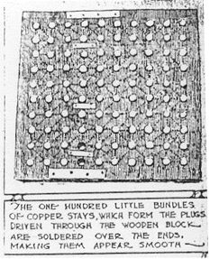
**Harry
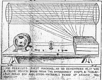
E. PERRIGO**
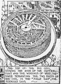
**Etheric
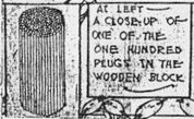
Wave Accumulator**
---
Perrigo's invention
eventually was exposed as an apparent fraud, at least in
part, but there is still some valid question whether it
might have actually worked as claimed. The storage
batteries that were found hidden in the demonstration
car might have served a legitimate purpose (i.e., a
buffer system, as in many other devices), but apparently
didn't. It is certain, however, that Perrigo had
something unique; his device lit bulbs with a clearer
light than normal electricity (Like E.V. Gray &
Moray), and the power could be transmitted over fine
wires without meltdown. While the automobile
demonstration was dubious, he also demonstrated a
handheld unit that obviously worked as claimed. Perrigo
also demonstrated the device before a federal judge and
patent commissioners in the House of Representatives in
1917. Would he have dared to fake such a presentation?
Only an attempt to replicate the device based on his
patent application will resolve the question. Here are
all the newpaper factoids I have been able to accumulate
(Thanks especially to the Kansas City Public Library
"Vertical Files").
---
**Excerpt** from
unidentified reference (probably by Dan Davis):
In 1926, Harry
E. Perrigo claimed to have discovered a method to tap
the energy from atmospherics. He even had a car which he
converted to run on electricity that was generated in
his "etheric wave accumulator". He applied for a patent
December 31, 1925, with serial number 78,715 being
assigned. Perrigo's patent application is considered a
classic in patent law and is listed under the
classification of "Perpetual Motion Machines & Other
Impossible Inventions".
Despite the patent
Office's attitude toward Perrigo's invention, there were
a number of reputable people who claimed to have
witnessed his device in action producing useable
electric power.
The existence of
electromagnetic radiation, the modern term, or electric
waves in the ether as it used to be called was known by
Hertz, a research scientist who discovered the
photoelectric effect in 1887. Atmospherics, an
electrical disturbance in the atmosphere, were known to
produce noises in the early radio telegraph stations,
some being strong enough to drown out the received
signal. Perrigo deduced that here was a possible source
of electrical power. All that was needed was a method of
transforming the existing radiation into useable energy.
He claimed to have developed a mechanism to intercept
and collect from the "general ether field electric wave
energy", and to transform it into useable electromotive
force.
The basic method he
used was an antenna arrangement which collected and
resisted the incoming energy and raised it to a high
enough current level where it could be run through a
special electrical transformer to further intensify the
available power.
Perrigo's antenna was
derived from his experiments with various wire shapes,
sizes and arrangements. One of his more successful
attempts was to partially pound 100 roofing nails into a
board 10 x 10 array and wrap very fine wire around each
nail, making it a small electromagnet. Then by trial and
error approach he connected the ends of the
electromagnets to other nails in such a way that there
was a maximum voltage between the wire and the nail. His
patent application mirrored this electrical connection
scheme in a more refined electromechanical approach.
Two accumulator plates
were made with 100 round protruding knobs in a 10 x 10
square array. The accumulator plates were then
sandwiched together with an insulator material between
them. The insulator had 100 holes matching the
protrusions on the plates. Placed in each hole was a
special coil wrapped around a bundle of wires. Once the
accumulator plates were sandwiched, a measurable
electrical voltage existed between points AA and BB on
plates 1 and 2, respectively. A very complicated
transformer was attached to these two points. The plates
were set on top of the transformer and Perrigo claimed
this arrangement enhanced the energy accumulation
process.
I have no idea of what
materials the plate or protrusions were made. The patent
drawing would lead one to believe they are the same
material. It could be a metal [lead has been mentioned,
or galena] or a non-conductor such as wood or a
combination. The protrusions were connected by the same
wiring scheme previously mentioned for the roofing nail
model. The connections were different for the two
plates.
---
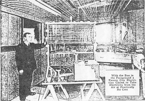
**Electricity As
Free As Air Is Inventor's Aim**
---
***Kansas City Star***
(February 29, 1916)
**[ No Title
Available ]**
It would be a dull
night in the 2500 block on Park Avenue when the
emergency ambulance didn't dash up with a pulmotor and
revive Harry E. Perrigo, who lives at 2511.
Mr. Perrigo is an
electrical engineer 8 hours of the day and an inventor
the other 16. he has invented a device for collecting
electrical energy from the atmosphere. Without dynamo,
transformer, generator or aught else, he is enticing a
constant current of 1500 volts down an aerial resembling
a wireless mast, it is claimed. Anyway, he is lighting
an 8-room house without visible means of support on the
part of the Kansas City Electric Light Company.
Last Friday night
while tinkering with the apparatus, Perrigo was made
unconscious by an electrical shock. He was revived by
his family and returned to his work. An hour later he
again got in the way of the maverick voltage and this
time it required the emergency ambulance and a pulmotor
to revive him.
Last night about 11
o'clock the "2511 Park Avenue" call again reached the
emergency hospital.
"Bring the pulmotor,
boys", shouted Dr James I. Tyree. Perrigo was revived
with a few minutes work. He had been tinkering again.
---
***Kansas
City Post*** (March 4, 1916)
**"Electricity
From
The
Air"**
Benjamin Franklin
stood in the rain nearly 200 years ago with a string of
a flying kite in his hand. Franklin discovered that
electricity was in the air.
Harry E. Perrigo, by
night and by day, stands in the little workshop behind
his home at 2511 Park Avenue and imprisons electricity.
Franklin did not know what to do with his wonderful
discovery. He did not realize how wonderful it was. But
Perrigo lives in an age when electricity has been made
to work and he knows what to do with the energy he takes
from the very atmosphere itself.
Perrigo has caught the
wild voltage in the air: has caught and tamed it. He
keeps it in a little box for everybody to use in
lighting houses, or running automobiles or machines or
street cars, heating homes, cooking or primping with
electric curling irons.
**Invention Ready For
General Use ~**
Just what is in that
little box is a mystery. It is kept sealed, air tight,
but no wires communicate with it from without.
Perrigo has perfected
the invention enough, he says, that it is ready for
general use.
"All that would be
necessary for one to obtain electricity for domestic
purposes", he explained, "is to install this little box
where the customary electric meter is placed at home.
Connect the wires in the house with the box on either
side and there you will have it.
"You can get any
amount of electrical voltage you desire by using the
required kind of transformer. You could get enough
voltage from the air through that box to light any
reasonable number of electrical lamps -- say a hundred
or more -- and the current costs nothing. It is as free
as the air from which it comes.
**Success Crowns His
Efforts ~**
It would take an
expert electrician to tell just how Perrigo tames the
electric currents from the air, and then it probably
would not be told in language which could be understood
by the ordinary individual.
Perrigo, more than a
year ago, concluded through experiments that there is
free electricity in the air. For months he spent his
waking hours in work and study until one night success
crowned his efforts.
He caught the
energizing element. But he caught it with his bare
hands, and paid the penalty by being rendered
unconscious from the shock. Since then Perrigo has
devoted all his time to improving his discovery and to
make it an item in the industrial and home lives of the
universe.
His experiments have
been attended by constant danger. Frequently he receives
the full force of the heavy voltage he is attempting to
control. He has made his more delicate tests recently
only in the presence of physicians. Not infrequently has
the pulmotor been brought into use in order to save his
life. But Perrigo always goes back to his work.
**Has Implicit Faith
In Device ~**
Some day, Perrigo
says, that little box of his is going to revolutionize
the production of energy for transportation as well as
for domestic use. When he tells of his faith in the
device it is not hard to believe that his success is
probable.
Perrigo has bright red
hair and his every movement is characterized by some
seemingly hidden force, as though the electricity with
which he works and plays has become a part of him. All
his working life Perrigo has been an electrician and has
been accustomed to handling high voltages.
And Mrs. Perrigo,
enthusiastic and balancing, is largely responsible for
her husbands success. It is from her that the hard,
everyday practical suggestions come while her husband
sits among his coils and transformers and testing
boards, dreaming out some new phase of the work. Mrs.
Perrigo suffers too.
Some days she fears,
the pulmotors may not prevail. Some day the monster with
which her husband wrestles may overcome him. Thats why
every time Perrigo goes into his workshop, he hears the
warning:
"Harry, be careful.
Use switches instead of your hands."
But Perrigo, absorbed
in his work, often forgets, and then -- a blue flame in
his hands, a splutter and a pop and the inventor gets a
shock that sometimes makes him unconscious.
But the little box is
there. He has done what he determined to do. He has
caught electricity from the air. Others, of course, have
generated it, but Perrigo takes only that which nature
has made.
---
***Congressional
Record*** (House), December 15, 1917, p.
357-372 (Excerpts, pp. 358, 363) ~
[Note ~ Perrigo
demonstrated his device in Congress on December 14,
1917. He was mentioned during a discussion ofHouse Joint
Resolution 174 concerning the so-called "Garabed"
invention of Garabed T. K. Giragossian, which was
claimed to be a free energy generator. Giragossian
wanted Congress to grant him exclusive rights beyond
those granted by Patent Law. His invention later was
proved to be impossible, based on erroneous
interpretation of gyroscope physics. Perrigo
demonstrated his device to show that there are other
ways to attain "free energy".]
Mr Garrett: The
purpose of the resolution, which by direction of the
Committee on Rules I have called up, is to provide for
the consideration, under the general rules of practice
of the House, of House joint resolution 174, Calendar
No. 77, entitled "Joint Resolution for the purpose of
promoting efficiency, for the utilization of the
resources and industries of the United States, for
lessening the expenses of the war, and restoring the
loss caused by the war by providing for the employment
of a discovery or invention called the 'Garabed',
claiming to make possible the utilization of free
energy"...
Mr Borland: A hearing
was had yesterday morning on an invention by a man named
Perigo [sic], who claims to have invented a machine to
collect electricity by free energy; that is, to collect
it from the energy of the air. In other words, his
invention is based on the idea, as I gather it, that
electricity can be collected from the air, where it must
be collected, by some other means than by the force of a
dynamo.
Now, if this is true
--- and I am not enough of a scientist to know --- there
may be many devices that are patentable for doing that
particular thing, or applying that particular principle.
If Mr Giragossian has a device for utilizing free
energy, his device or machine or appliance is
patentable, but the principle of free energy evidently
is not patentable under the existing law. Anybody else
who produces a better machine for utilizing free energy
is just as well entitled to use it for the benefit of
mankind as the man who first obtains the patent on it.
In other words, we cannot foreclose that principle.
Now, we have got a
machine here in the Capitol --- I undrstand from Judge
Romjue a few minutes ago that the machine which Mr
Perigo had demonstrated before the Patent Committee had
been brought over here. It was shown to the Patent
Committee. It is in a small box. I have seen it. I would
not know anything about it. It runs a dynamo or motor,
and it lights certain lights. In other words, there is
some power in that box. What that power consists of I
have no means of knowing. The inventor says it contains
free energy. In other words, this device has been
brought to a state of completion. It is in actual
working order.
Now, it does seem to
me that this bill ought not to be passed at all unless
it provides that this committee of scientists shall not
only have the power but it shall be charged with the
duty of ascertaining whether or not this device of Mr
Giragossian utilizes the same principle of free energy..
---
***Kansas
City Star*** (January 15, 1922)
**"Mr.
Perrigo's Own Conception of What His Invention
Means to the Future"**
The steam engine will
be abolished from industry. Trains and trolley cars will
be operated by free energy.
Aviators will be able
to circle the earth without coming to the ground for
fuel.
The maximum speed of
ocean-going ships will be increased from about 23 knots
an hour to more than 100, by the conservation of the
space and tonnage now used by mammoth boilers and coal
bunkers. Manila will be nearer to Kansas City than San
Francisco is today. The trip from London to Boston will
be made in 30 hours. Asiatic fruits will reach New York
fresher than California fruits arrive now.
Aluminum, produced
cheaply and abundantly by free electricity, will replace
wood and steel in the manufacture of ships, buildings,
cars and furniture. The world will be benefited by the
preservation of forests, and great fire disasters will
end.
The expense of motive
power in transportation, travel, and communication will
be eliminated.
The present system of
agriculture will be changed materially. Every farmer
will have abundant power. Underground streams can be
reached and ever-pouring water will be available in all
regions. Millions of arid and deserted acres will be
transformed into productive fields.
Nitrogen for
fertilizer will be extracted electrically from the air.
Hours of labor will be
reduced while industry and production increases.
---
***Kansas City Star***
(January 15, 1922)
**[ No Title
Available ]**
Imagine: without
gasoline, or other fuel, without storage batteries or
generator, a motor car holding its place in the flow of
traffic on a busy Kansas City street.
Imagine: over Kansas
City, 1,000, 5,000, 12,000 feet from the ground, an
airplane soaring. Without a drop of gasoline or petrol
on board, without storage batteries, without generator,
without even an engine, it loops and dives and flies
away.
Imagine: In your
little cottage or apartment, your big house, electric
lights burning steadily. Imagine your wife in the
kitchen, getting dinner. Imagine you see her turn a snap
switch beside the oven door and put her potatoes in to
bake. Yet you know that the power wires going into the
cottage apartment or house are cut off at the meter and
are "dead".
Imagine: there will be
no electricity and gas bill at the end of the month.
Imagine the motor car,
the airplane, the house lights and oven, powered and
lighted and heated by electricity --- electricity from a
little wooden case 14 inches square and weighing less
than 90 pounds.
Is it past all
imagining? Are you a skeptic and do you point to the way
the entire country has been fluttered in the past by
announcements of fuel made from ashes and gasoline from
water, and nothing has come from it? You may be right to
be a skeptic. But the years Harry E. Perrigo, 3000
Michigan Avenue, has spent inventing and perfecting the
little machine in the wooden case entitle him to the
attention of the public, especially his neighbors in
Kansas City.
The dream outlined
above will be true within a year, Mr Perrigo declares.
It will be realized by his invention, he says, a device
he calls the Perrigo.
Mr Perrigo is an
electrical engineer, educated in the Massachusets
Institute of Technology. More than 10 years ago, while
working in a power plant in Pee Dee, SC, he touched a
wire, "dead" so far as any connection with any source of
power was concerned, and found it charged with
electricity. His idea came then.
If a wire, suspended
in air, gathered atmospheric electricity, why couldn't
that electricity be accumulated, condensed and converted
into power?
Telling his own story,
Mr Perrigo said he kept the idea in mind constantly,
thinking out devices, drawing sketches. He explained it
to Mrs Perrigo, and talked over plans with her. She was
enthusiastic, as any good wife would be, without any
definite idea of what it was all about.
**The Building of the
First Machine**
Then one night, early
in 1915, came the inspiration to act. Mr Perrigo lived
at 2511 Park Avenue at the time. Stores and shops were
closed, but with two or three strands of copper wire
from the basement, with two embroidery hoops from Mrs
Perrigo's work basket, with a leaf from the dining room
table, with the bread box from the pantry, with a sheet,
torn into strips, with shingle nails and paraffin, Mr
Perrigo, with Mrs Perrigo's aid, made his first "free
energy" device. And it worked.
Before noon the next
day, he said, electric lights were burning and a small
electric motor was running from the power developed in
the crude tangle of wires on the Perrigo dining room
table.
The neighbors came in
to see. Among them was Dr Bert McDowell, a dentist with
offices at 4301 Main St.
"I couldn't believe my
eyes", Dr McDowell said the other day. "I had to be
convinced, because the thing was there in plain sight
and I knew Harry wasn't getting his power from outside,
because his house was not even wired for electricity. He
used gas for lights."
"Yes", Mr Perrigo put
in, "I was so fascinated with the thing I had made that
I kept that little motor running constantly for two
weeks. It buzzed and hummed and rattled frightfully, and
gave my wife a headache, but she didn't complain, and I
kept it going."
**Handicaps Were
Many**
Mr Perrigo's story
from that point on is one of five years of patient,
unending work to perfect the Perrigo. It is one of long
days and nights of toil, of sickness, failures, lack of
money, the hooting of unbelievers, organized opposition,
the hearty cooperation of a real helpmate.
The Perrigo basement
is piled high with coils and plates of many sizes and
shapes, steps in the evolution of the present compact
design, which, Mr Perrigo says, with the patents
virtually proved, is ready for manufacture on a
commercial basis.
From the pile, Mr
Perrigo dug out the other day a board, 12 inches square,
an inch thick, both faces covered with shingle nails,
set a half inch apart, each extending an inch out of the
board.
Each nail was wound
tightly with silky fine copper wire, smooth spirals one
atop another. The wires led from one nail to another,
some from top to base, some from top to top, some from
base to base, each wire soldered carefully in place.
"Mrs Perrigo did all
that for me", Mr Perrigo said. "She worked until long
after midnight many nights. The job took weeks to
complete. Then the thing wouldn't work. It's just one of
a lot of experiments we put time and money into, only to
find it was not the right thing."
From his first crude
machine, Mr Perrigo, in his search for perfection,
evolved may different types. At first he worked on the
idea of an aerial to gather energy. A workshop he fitted
up was strung with a network of wires. The wall was
driven full of nails wound with copper wire.
"The machines I made
out there did the work", Mr Perrigo said, "but they were
bulky and bunglesome and got out of order easily.
"Other things than
getting rid of bulk bothered me, too. My early machines
were affected by passing air currents. Power would
increase when I fanned the machine or when a person
walked past it, and decrease when the atmosphere was
calm.
"The machine I have
now gives a steady flow of current, whether in the
basement, 14,000 feet in the air, in a motor car or on a
fast moving train. The copper pegs in the wooden block
do that."
**The Completed
Machine**
The Perrigo consists
of only four parts: two lead plates, a wooden block and
a coil of copper wire. The coil that Mr Perrigo says
will deliver 500 horsepower is 10 inches across, 4
inches high, of solid copper. Fine copper wire is wound
smoothly about neat rows of copper stays, hardly larger
than a toothpick, but longer, as long as the coil is
high. The wire is connected in many devious ways. In
those connections is the secret of the mysterious power.
The lead plates for
this size Perrigo are a foot square. On each plate are
100 spring coils of copper wire, spaced in rows, an inch
apart. The plates appear identical, but are different in
the way the connections of hair-like copper wire run
from one coil to another.
The wooden block is a
foot square, also, and an inch thick. One hundred copper
plugs run through the block, spaced just as the coils on
the lead plates are spaced. Each plug is a bundle of
copper stays, making a contact.
That is all there is
to the Perrigo, so far as anyone can see. Complete, the
500 horsepower size weighs 87 and one-half pounds. There
are no moving parts.
A Perrigo to operate
an ordinary size motor car need be no larger than a
1-pound coffee can", Mr Perrigo said. "A size to provide
all the current needed to heat and light a 5-room house
will go into the can. The different sizes can be made to
furnish any desired voltage, and either direct or
alternating current, by a slight change in the wiring."
**The Inventor
Explains It**
Trying to avoid
technical terms, difficult business for an engineer, Mr
Perrigo explained his invention this way:
"The device is a
generator as truly as the power-driven rotary generator
in any power plant. Those generators don't actually
'make' electricity. They condense it from the air. So
does the Perrigo. But it does it through the system of
wiring, rather than revolutions through a magnetic
field. I get my starting point from the air by breaking
up the ether waves. The coils on the lead plates do
that. I know why they do. It's the way they are
connected, one from the other. That's my secret.
"They do break up the
ether waves, gathering electricity and conducting it
into the big coil underneath. That's the generator. Its
size and the way it is wired determines the voltage, the
horsepower. Outgoing wires from this coil take the
'juice' where you want it and it is there when you want
it."
Mr Perrigo has great
plans for his electric 'chore boy' and great faith in
it.
"It will replace every
other source of power, light and heat", he predicts. "It
means the doom of the steam engine, the end to coal
mining, to the cutting of timber for fuel. It means
petroleum will be used only for lubrication. It means
smokeless, sootless cities. It means chimneys will
disappear from housetops. It means cheap power for the
farmer, the reclamation of much country that cannot be
irrigated now because power is not available."
**What Other Persons
Think ~**
Mr Perrigo is able to
impart his faith to others, too. The enthusiasm of
persons who have seen the device work is second only to
that of Mr Perrigo himself.
S.W. Fries, an
electrical engineer, and district sales manager here for
the Economy Fuse and Manufacturing Company, saw the
Perrigo first about three months ago.
"When I heard about
the machine through Dr McDowell, I told him it couldn't
be done", Mr Fries said the other day. "I've been
converted. I don't know how it works, but it does. Its
possibilities are too big to grasp. Its use will mean a
new age in industry. I believe Mr Perrigo will be the
most widely known inventor in the world as soon as his
device comes into general use, and he will become one of
the world's most wealthy men, just from returns which
already seem assured."
"Mr Perrigo gets
enough electricity from somewhere to knock him
unconscious", Dr O.W. Butler (3700 Benton Blvd) pointed
out. "I've been called to his house many times in the
last four years to revive him, and once I carried him
out of his basement. He has worked at his experiments as
long as four days and nights without sleep --- worked
until his health is broken and his constitution is a
bundle of jagged nerves."
"How are you going to
manufacture your machine and get it on the market?" Mr
Perrigo was asked when he asserted there was no stock
for sale and he was seeking no financial aid.
"Responsible backers
are furnishing all the money I need for experiments,
models for the patent office and other work I'm doing
now", he answered.
"As soon as one final
amendment to my patent application is approved I'll be
ready to permit motor car manufacturers to make the
Perrigo in their own plants, charging them a small
royalty on each machine. They will be eager for it when
they see what it is. This will provide funds enough in a
short time for my associates and myself to being to
manufacture the machines for home use.
"We don't expect to
sell the Perrigo. We will lease them on the same plan
the telephone companies use for their machines, charging
a monthly rent, probably about $3 for a 5-room cottage
size. That's cheap enough, isn't it, for all heat and
light and power?
"I've always said I
never would sell out to any big corporation. My
invention is for the benefit of the poor amn. Even on
that basis I'll get more money out of it than I can ever
use."
**The Householder's
Point of View**
Mr Perrigo explained
that it will not be necessary for the householder who
desires the Perrigo installed to buy an expensive
electric furnace, electric range or any special
equipment.
"A gas range can be
wired through the pipes which now carry gas", he said.
"It will be necessary only to replace the gas burners
with electric heating plates and install snap switches
where the gas valves are now. A furnace can be fitted in
the same way, by removing the grate. No change will be
necessary with the lights. The new machine will be
installed where the meter is now. That's all."
"When one man has a
machine, won't it be possible for his neighbors to come
in, see how it works, and manufacture their own?" Mr
Perrigo was asked.
"No", he answered,
"Each one will be sealed, just as the electric meter is
sealed. To break the seal will put it out of order and
the subscriber will have to call for a 'trouble' man.
Anyway, if a man would take one apart he couldn't put it
back together again without my drawings and blueprints.
That's my secret and I'll keep it."
**A Demonstration ~**
When a visitor
expressed a desire to see a machine actually produce
light or power or heat, Mr Perrigo acquiesced. He went
to the basement and returned almost immediately, bearing
a boxlike affair, mounted on a little platform. A small
electric motor, light sockets and switches were on the
platform. The top of the box was glass. Through it Mr
Perrigo pointed out parts of the machine inside.
Mr Perrigo fastened
the loose ends of two wires that extended from the box
to the connection posts of the motor and pushed a switch
button. The motor started at once. The inventor said he
had not changed the machine or even opened the box,
which was closed with screws since he made it five years
ago.
---
***Kansas City Star***
(March 27, 1922)
**"Can't
Use His Invention"**
**Patent Laws Prevent
Demonstration, H.E. Perrigo Tells Inquirer**
Miami, OK --- To *The
Star*: "In your paper of January 15 there appeared
a wonderful story relating to the invention of Harry E.
Perrigo, an electrical engineer of Kansas City, of a
device to generate electrical energy.
"One got the
impression from reading the story that Mr Perrigo's
device was a demonstrated success, that it had been
patented, and that he was practically ready to permit
its manufacture as a source of power.
"It was a whale of a
story and interested me, for it seemed if it were true
that his device was destined to have as far-reaching
influence on the human race in the future as the grain
binder and the gas engine had had in the past.
"I wrote to various
publications devoted to mechanics and electricity,
seeking further information. None knew anything about
it. One said no such device had been patented, another
that a vast amount of research and experimentation had
been done in an effort to develop such a device and that
the only result had been failure.
"I would like to know
if Mr Perrigo's device has been patented and if he is
prepared at the present time to demonstrate it in a
convincing way."
The story of Mr
Perrigo's invention was printed in the Star as the
record of an ambitious and interesting enterprise. The
apparent success of the device was vouched for by
persons who had seen the machine in operation and were
convinced it produced the results Mr Perrigo claimed for
it.
Questioned recently as
to new developments, Mr Perrigo said there could be no
new mechanical developments.
"The machine has been
developed to a state as near perfect as I can make it,
for two years", he said. "I am waiting for the patent
office to take final action. My applications have been
approved and investigation has shown no conflicting
patents on record. The rest is simply a matter of
routine work in the patent office. As soon as the final
patents are granted I'll be ready to manufacture the
Perrigo.
"I can't give a
demonstration without going to considerable trouble to
set the machine up. Of can't keep it set up, nor even
use it in my home, because technically that would amount
to 'commercial use' and would interfere with the
granting of patent rights.
---
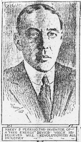
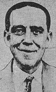
(1) Harry E. Perrigo,
the inventor of a "free energy" device which he believes
will revolutionize all industry ~
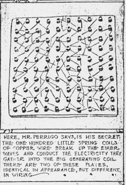
(2) Here, Perrigo
says, is his secret: the 100 little spring coils of
copper wire break up the aether waves and conduct the
electricity they gather into the big generating coil.
There are two of these plates, identical in appearance
but different in wiring.
(3) The 100 little
bundles of copper stays form the plugs driven through
the wooden block are soldered over the ends, making them
appear smooth.
(4) Mr. Perrigo's
first machine, as he remembers it, was a crude device
made from two embroidery hoops, a table leaf, bread box
and other materials picked up around the house.
(5) The top of the big
coil, showing the ends of the copper stays and the
windings of wire. The space separating the two parts of
the coil are the "field gap", Mr. Perrigo says.
(6) At left, a closeup
of one of the 100 plugs in the wooden block.
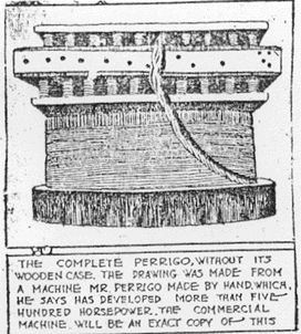
(7) The complete
Perrigo, without its wooden case. The drawing was made
from a machine Mr. Perrigo made by hand which, he says,
has developed more than 500 horsepower. The commercial
machine will be an exact copy of this.
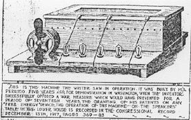
(8) This is the
machine the writer saw in operation. It was built by Mr.
Perrigo 5 years ago for demonstration in Washington,
when the inventor successfully opposed a war measure
which would have prevented for a period of 17 years the
granting of his patents on any "free energy" device. The
operation of this machine, on the speaker's table in the
lower House, is recorded in the ***Congressional
Record*, December 15, 1917, pages 369-383.** [Actually,
pp. 357-372]
---
***Kansas City
Journal*** (August 7, 1927), page 1
**"Power
Drawn From Air Propels Auto Over K.C. Streets"**
**Inventor Claims
Tiny Motor Will Drive Plane Around World, Doing Away
With Transportation of Fuel**
A motor car was driven
40 miles an hour in Kansas City yesterday on power drawn
from the air.
A device making this
feat possible was demontrated after years of rebuffs and
failures by its inventors, Harry Perrigo, 1116
Bennington Avenue, in the presence of Col, Paul
Henderson, Chicago, vice president of the National Air
Transport Inc., air mail contractors.
"It is the greatest
invention since the stone age", was Col. Henderson's
comment.
Lou E. Holland,
president of the Chamber of Commerce, who saw the
demonstration with Col. Henderson, was enthusiastic over
the invention and said he believed it would have a great
effect on public utilities if it can ever be brought
into general use.
**Coils Gather
Power**
The device consists of
a plate 14 inches square which, by a multiple
arrangement of connected copper coils, it was explained,
attracts electric current from the air.
The electricity thus
trapped passes through a generator and to a regular
direct current motor, which was connected to the
transmission shaft of the car.
Mr Perrigo has been
working on the device more than 10 years. Three years
ago he suffered a nervous breakdown and has been back at
his workshop only two months.
While photographers
focused their cameras, Mr Perrigo and his wife entered
his roadster in which the device was installed. He
turned a switch and the motor hummed.
The inventor sat
silent, listening. Then he threw in the clutch gently.
The car moved away with only the sound of the cogs,
whining softly as they meshed. He threw it into high and
sped away.
At the corner of 10th
Street and Bennington Avenue, near his home, he stopped
the machine while movie cameramen ground their machines.
Then he backed it and turned around, stopping in the
middle of the street.
Later Mr Perrigo took
the car out for a spin. It breezed along at 40 miles an
hour.
**"100 Just As
Easy"**
"I could make it go
100 miles an hour just as easily", the inventor
remarked, "if it were not for the danger of hurting
someone."
The total weight of
the motor, generator and controls is about 86 pounds,
according to the inventor. In the rear of the car are
reduction coils, because the device is five times too
powerful for the work of pulling the car, Mr Perrigo
said.
The proper motor for a
Reo car will not weigh more than 30 pounds", he said.
"The motor to run a Chevrolet will weigh not more than
10 pounds. An airplane motor would weigh around 50
pounds, and with that motor the air traveler could go
around the world without waiting."
Col. Henderson walked
around the machine, inspecting it.
"What it would mean to
my airplanes", he said, "--- no weight for motors, no
space for gas, no motor trouble."
Like other spectators,
he had difficulty in believing what he saw.
The work of bringing
the invention to its present state of development has
been the story of a lone man working with the unknown,
usually meeting with discouragement.
**Congress Wouldn't
Believe**
Five years ago, the
inventor took one of his electric motors to Washington,
set the boxlike contrivance on the speaker's stand in
Congress and ran a motor and five lights with it. They
called it an infernal machine.
Even now, when he is
seeking patents for his invention, the patent office
refuses to believe the principles he advances are
possible.
"The machine has been
taken up in an airplane 10,000 feet and it operated the
same as if it were on the ground", Mr Perrigo said. "It
has been tried out in hot places and cold places."
He pictures it as
power for every purpose --- the farm, the factory, the
office, doing away with coal, gas, cost of water power
and the cumbersome weight of engines.
The models of the
machine now are being kept in bank vaults.
Mr Holland is
convinced, after two weeks investigation, that the
invention is genuine.
---
***Kansas City
Journal*** (August 8, 1927), p. 3 ~
**"Perrigo
Dreams
Of
Aiding Humanity With Ether Wave Machine"**
**Inventor Declares
Generator, When Patented, Shall Not Be "Hogged" or
"Shelved", But World Will Reap Benefits Of Cheap
Power.**
Homes lighted and
meals cooked for a cost of $5 per month; motor cars
operating with a quart of lubricating oil about once
every six months and a little grease in the rear axles
and yet damaging no existing corporations by the working
of these revolutions.
These are the dreams
of H.E. Perrigo, 1116 Bennington Avenue, inventor of the
Perrigo ether wave generator.
Lou E. Holland,
president of the Chamber of Commerce and Col. Paul
Henderson, general manager of the National Air
Transport, Inc., are convinced his invention is
practical.
Mr Holland, Mr
Henderson and newspaper men Saturday witnessed a
demonstration in which Mr Perrigo drove a motor car on
electric power generated from the air.
"It is too early yet
to talk to manufacturing the invention", Mr Holland said
yesterday. "The patent rights must be perfected in both
the United States and foreign countries. Also, it must
be made clear that nothing will be done to demoralize
present power manufacturing."
Mr Perrigo's invention
is the result of more than 12 years labor on the part of
the inventor.
"Twelve years ago I
conceived the idea that the generation of power from
ether waves was possible, while I was employed ion the
power plant at Pee Dee, NC, where some wires not
connected with anything that was 'live' seemed to be
generating power", Mr Perrigo said yesterday.
"After more than a
year of experimenting I finally produced light in a bulb
about the size of those used in flash lights. Now in my
laboratory I light three 300 watt globes from a wire no
larger than the thread which holds the button on a man's
overcoat.
"Three times in my
experiments I was knocked unconscious because I did not
know how much power it would generate.
"The invention has
been tested under all conditions. It has been strapped
to the running board of a locomotive running between
Kansas City and Chicago, it has been tested in an
airplane at a height of 12,000 feet. It will generate
power anywhere that air circulates.
"With the invention
every home will have its own power plant and all the
electricity needed for any purpose can be provided at a
roughly estimated cost of $5 per month.
"The Kansas City
Public Service company, for instance, could afford to
install these plants because they would eliminate the
enormous overhead which is the principal expense of such
companies."
Both Mr Perrigo and Mr
Holland made it plain that the invention will not be
permitted to upset the electrical world. No one will be
given exclusive rights of its use, they said.
"Any person or any
manufacturer can use the invention who will pay the
royalty fees", Mr Perrigo explained. "No one will be
permitted to 'hog' the invention and no one can purchase
it and shelve it.
"I have no doubt that
it will bring me more money than Mrs Perrigo and I will
need to supply our simple wants and I want humanity to
benefit.
"I want to see rural
sections which have remained barren because it cost too
much to pump the water to irrigate them, spring into
bloom. I want to see the smallest farm house in the most
isolated places with its electric lights and stoves; in
other words, I want humanity to benefit."
"How about the
gasoline industry if motor cars are to be run without
fuel?" he was asked.
"The supply of
petroleum is limited", he answered. "There are 30 other
purposes to which petroleum products can be turned, so
the oil producers will not suffer."
"Can you explain your
invention so that the non-technically trained can
understand it?"
"That would be
difficult, especially without divulging information that
is now in the patent office; besides, the generation of
power always is difficult to explain.
"Electric generators
have been used in power plants for a great many years.
We all know what you have to do to make a generator and
we all know that electricity is its product but we don't
know very much about what really is going on inside that
generator."
While the patents for
his device still are pending, Mr Perrigo is keeping his
working models in the vault of a downtown bank to
prevent the possibility of their being copied.
---
***Kansas City Star***
(August 7, 1927)
**"Electricity
Power
from
Air?"**
An invention that will
revolutionize radically all power producing and power
using machinery of the entire world, if in practical use
it equals the miracle of its demonstration, was given a
showing here yesterday to newspaper men and Lou E.
Holland, president of the Chamber of Commerce.
It is a device to
collect electrical energy from the ether and convert it
into a powerful current of electricity of a type
dissimilar in many ways from the direct or alternating
current now known to electricians.
So far as could be
determined even by the most skeptical of those
witnessing the demonstration yesterday, the device is
exactly what Harry E. Perrigo, the inventor, asserts it
to be -- a method for collecting natural electricity
from the ether, in unlimited quantity and without cost.
**More Power Than
Needed ~**
One feature of the
demonstration was the operation of a motorcar by power
from a small model of the invention. The engine had been
removed from the car and an electric motor substituted.
The device supplied power in such quantity that it had
to be reduced and yet propelled the car with speed and
ease.
A detailed examination
of the car showed the absence of any possible form of
power except the inventors small device and it is of
such an open type that one may see clear through the
mass of wires and coils.
Other demonstrations
were given with other models of the device, with the
machine and electric lights and motors held in the hands
of spectators, yet the device produced current to do any
electrical task assigned to it.
Col. Paul E.
Henderson, general manager of the National Air
Transport, Inc., was there with Mr Holland, being his
guest for the day. He took an active part in the testing
and enthusiastically was declaiming the invention as
revolutionary.
**Cheap As Similar
Motor**
To operate a motor car
would require a model weighing about 20 pounds, Mr
Perrigo computes, but he has given no thought the
probable cost of building it. However, he estimates the
cost at no more than an electric motor of the same size.
A device of the size
of a coffee can would light and heat an average home, he
declares, cutting off forever all fuel and lighting
bills.
And one can go on and
dream of an electrified world with free power for all
industries and operations, increased yields of foods
from dry areas that cold be irrigated with this free
energy, the passing of wood and coal and oil as fuels.
At first thought, not
one of the persons seeing yesterday's demonstration
could give much credence to the inventor's declaration
that his invention was a way to obtain unlimited
electrical power from the ether without any cost.
There was not a
doubter left as to the success of the demonstration, but
the witnesses could not in any sense qualify as
electrical engineers.
**Electricity Always
In Ether**
As near as a layman
can understand, Mr Perrigo's theory is the revolution of
the earth sets up a form of electric currents that are
forever present in the ether. His theory is to capture
those electrical impulses in very much to same way that
a radio antenna picks up the programs broadcast from
WDAF. Instead of a machine to turn the radio impulses
into music, Mr Perrigo has a machine to turn the ether's
electrical store into controlled power. He declares it
is really no more mysterious than the fact that an
electric dynamo picks electricity out of the air,
although the dynamo must have a power to revolve it
while his device sits perfectly still and seemingly
produces many fold more electricity than a dynamo of the
same bulk.
Demonstrating the
different nature of this electricity, Mr Perrigo showed
how high voltage could be transmitted over hair-size
wires and light a series of electric lamps although a
sufficient power of the well known electricity to light
those lamps would have melted the small wires
immediately.
**Clearer Light Than
Usual**
And it imparted an
unusual glow to the electric lamps, giving them a clear
brilliancy with none of the effervescent haze that
surrounds the wires in a lamp when lighted with ordinary
electricity.
Mr Perrigo has spent
years on his invention. Years ago he conceived the idea
that there was an unlimited source of electricity in the
air that could be harnessed with a collector. He has not
reached the present measure of success without a row of
hard knocks along the way.
In whatever
neighborhood he has lived since moving here 15 years
ago, it has been common knowledge that Mr Perrigo was
the frequent victim of electric shocks that often came
near proving fatal. He has been revived by pulmotors
time and again.
The first model of his
device was constructed with makeshift material. A leaf
from Mrs Perrigo's dining room table was the basis, with
the bread box used, sheets torn up and the strips
shellacked to be used for insulation. But as junky as it
was, it operated a small motor, and that original model
is still preserved and used a s part of his
demonstration.
**Sickness Delayed
His Work**
In 1922 he got the
device to such a point of perfection that he went before
Congress and defeated a war-time measure that proposed
to give 17-year rights to another person for a blanket
patent on all free energy devices.
Then three years of
sickness came, and the invention progressed slowly. Mrs
Perrigo is not electrically inclined, but she has
carried forward the experiments under his direction and
has always been his assistant.
Mr Perrigo is not
offering stock for sale and says he has made all
necessary arrangements for financing the device when it
is ready for manufacture.
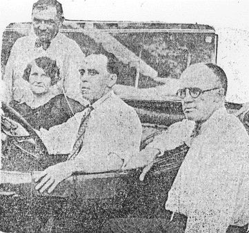
**Photo
Caption:** In a semi-public demonstration here
yesterday of an invention said by its inventor to be able
to collect electricity from the ether, in unlimited
quantity and without cost, a motor car was propelled with
perfect success, then an examination of the car allowed to
show the absence of engine, storage battery or other usual
form of power. The upper photograph shows under the
motorcar hood, engine missing and an electric motor in its
place. The equipment above the motor is a series of
resistance coils, the collection device used being too
powerful for the motor. The middle photograph shows the
collector placed on the floor by the driver, a makeshift
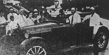
arrangement for the test. Below is Mr Perrigo, with his
wife, seated in the test car. Lou E. Holland, president of
the Chamber of Commerce, is standing on the near side of
the car. Col. Paul E. Henderson, general manager of the
National Air Transport, Inc., stands on the other side.
They were among those attending the demonstration.
---
***Kansas
City Times*** (August 8, 1927)
**"Electricity from the Air"**
H.E. Perrigo, a
nervous, red-haired little electrician, stood last nigh
among a confused display of strange devices in is
basement workshop at 1116 Bennington Avenue. He was
still a bit haggard from an illness of three years, but
is energy, dynamic as that which his devices "pick out
of the air", was unabated. Mr. Perrigo had just returned
from a conference with Lou E. Holland, president of the
Chamber of Commerce.
"There are no
batteries in this room", he said. "There are no light
and power wires. There is nothing but these unconnected
accumulators you see before you."
On an old kitchen
chair stood an object about one and one-half feet
square, several inches thick. It appeared to consist of
two parallel metal squares, separated and held together
by numerous pegs woven around which was a maze of thin
copper wires. It stood on edge, resting against the back
of a chair. On the seat of the chair was a round
metallic object, resembling, at a glance, a huge spring,
a foot and a half in diameter, from an alarm clock. In a
mechanical sense it was in no way similar. But it might
as well have been an alarm clock spring, for all Mr.
Perrigo would tell of its construction. The first object
was the collector, the second the generator.
**No Moving Parts, No
Wheels**
Neither had any moving
parts. They have no wheels. They are immobile, simply an
arrangement of wires. On the to edge of the flat box was
a switch. Thence ran two wires, connected with
forty-five 100-watt standard electric light bulbs.
Mr. Perrigo pulled the
switch. There was no arc as the contact was made. The 45
bulbs flashed brightly and burned with a steady white
glow. There was never a flicker. He turned 44 lights
off, leaving one. It did not flicker as the 44 lights
went off and on.
"This little device,
the Perrigo Electric Accumulator", said Mr. Perrigo,
will light 8,000 bulbs as easily as it lights one. I can
build one of any size, to produce the results that any
amount of dynamo electricity will produce."
He picked up a little
narrow box, in the top of which was a pane of glass,
through which one might see more pegs, more intricate
wiring. He connected a small electric fan to the poles,
and the fan whizzed.
**Tests Everywhere
But Under The Sea**
"There are skeptics
yet", he said. "Some think I am picking up leaking
electricity. This free energy device has been tested at
an altitude of 12,000 feet, on the sea, on deserts,
everywhere except in a submarine. Everywhere it runs
smoothly, without fluctuation".
In his Reo roadster he
had a large motor mounted, the one he demonstrated
Saturday to Lou E. Holland, president of the Chamber of
Commerce, and Col. Paul E. Henderson, general manager of
the National Air Transport, Inc. Mr. Perrigo crawled
into the seat, threw a switch, and a big all-speed
motor, standing in the place of the gasoline engine,
roared.
"Rheostat control",
said Mr. Perrigo. "It will run at all speeds. I do not
need clutches".
There were two
"mystery boxes" in the car, one of which picked the
electricity out of the ether, the inventor explained,
another which regulated its intensity.
"It will be on the
market in the near future", Mr. Perrigo said. "I cannot
say more at this time. It will be manufactured by a
Kansas City company.
"We do not intend to
harm the men who produce electrical current by other
means. Perhaps they will manufacture and distribute the
little units. The can do it gradually, so there will not
be a sudden, destructive revolution. That is bad
economy. There is to be no monopoly. But eventually
there will be a unit in every home. There are no moving
parts. A unit will last a lifetime".
Patents were pending,
Mr. Perrigo said.
**His Idea 15 Years
Old**
The germ of the
invention, Mr. Perrigo related, came to him 15 years ago
in Pee Dee, NC, when he was employed in an electric
power plant.
"All of the dynamos
were off", he said. "I was working on a dead one. I
encountered some hot wires. Yet there was no juice being
produced. It gave me an idea. Three years later I began
developing it. I have worked on it since at odd times.
About 8 or 9 years ago I began intensive work on it. I
demonstrated it experimentally in 1922. Now it is
perfected. I want the world to know it is a reality".
Mrs Perrigo came
downstairs and cautiously proceeded into the workshop.
"Is the floor too
wet?", she asked. "Might I get a shock?".
He reassured her.
"Ive been laid out so
often", he said, "no wonder shes timid".
There was a tremor in
Mrs. Perrigos voice as she spoke.
"I'm so glad it's all
over", she said. "We've given years of our life to it,
Mr Perrigo almost has broken his health over it. It's
done. We can rest now."
Mr Perrigo leaned
against the wall and talked.
"Think of what it can
do for the world", he said. "Money isn't all. It will
give the farmer unlimited power. It will drive motor
cars, run the washing machine, carry an airplane
forever. Can't you imagine what all it will do?"
Some one suggested man
would never have to do another lick of work on earth.
"Oh, no", said Mr
Perrigo. "He must never quit working. He must work on
and on and on."
Definite steps were
being taken to protect not only the inventor but the
user and producers of electrical current, Mr Holland
said last night, following a conference at his home.
**Must Protect Users
& Makers**
Mr Perrigo's invention
is so revolutionary in scope that many interests into
its manufacture and use", Mr Holland said. "All of these
interests, the big producers of power and the users of
electric current are concerned and how these interests
along with those of the inventor shall be protected is a
matte for first consideration."
It was pointed out
that there were innumerable corporations engaged in the
production of electric current and billions of dollars
invested in power plants, machinery and transmission
lines. The successful use of the Perrigo device would
make the power plant systems of the country obsolete.
No stock was offered
in the invention, Mr Perrigo said. Arrangements have
been made for financing the manufacture of the device
when it is ready for the market.
"The parent company
will be here and the first machines made in Kansas
City", Mr Holland added.
---
***Kansas
City Journal-Post*** (August 8, 1927)
Harry Perrigo, 1116
Bennington Avenue, inventor of a device which, he says,
draws electrical energy from the air, yesterday
demonstrated the invention before Col. Paul henderson,
vice-president of the National Air Transport, Inc., and
Lou E. Holland, president of the Chamber of Commerce.
The device was used to propel a motor car from which the
motor had been removed at a rate of 40 miles an hour.
Mr & Mrs Perrigo
are shown in the motor car. Mr Holland stands at the
left of the car and Col. Henderson on the right ~
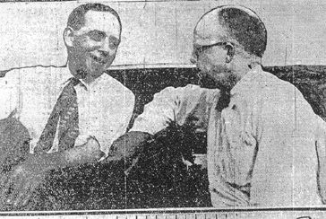
Mr Perrigo at the
wheel, explaining the apparatus to Col. Henderson ~
A closeup of the
mechanism. At the left is an ordinary motor. A cog wheel
on the motor shaft meshes directly with a larger cog on
the main drive shaft of the car. The square mechansim at
the top is the controlling device
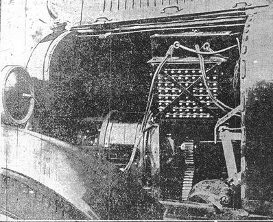
---
***Kansas City Star***
(August 8, 1927)
**"A Magnet For Money, Too"**
**The Power From Air
Machine Has Been Backed for 14 Years --- Some Still
Are Faithful to It.**
The "energy from air"
device demonstrated Saturday by H. E. Perrigo when he
seemingly operated a motor car with electricity taken
from the free air, got almost as much attention today
when investors bobbed up from all corners of the city
and told of having bought shares in his device as far
back as 14 years ago.
So many tales of
investing as much as $10,000 in Perrigo's hope came to
light today that the state blue sky commissioner and the
Better Business Bureau began an investigation.
**The Investors Are
Interviewed ~**
Several of the
investors in Perrigo's device were interviewed by those
agencies.
All the investors
talked to were of the opinion that Perrigo was
impractical as an organizer, to say the least, and that
they had been swindled on a gigantic fake or that
Perrigo really had some great invention, but was
unnecessarily slow in commercializing it.
Preston T. Stockard,
blue sky commissioner, said after talking to a few of
the investors that he would demand a showing of the
merit of the apparatus, and would question Perrigo as to
his financing plans, preparatory to issuing a "stop
order" against any more sales of stock.
Mr Perrigo said at the
demonstration Saturday that he was selling no interest
or shares in his invention and that he had met expenses
while experimenting by doing outside electrical work.
Mrs Perrigo, however, said their financial problems had
been met by "occasional financing as is always done".
As far back as 5 years
ago, a group of persons who had invested met and
discussed the possibility of prosecution for the share
sales or of taking some action to get control of the
device away from Perrigo and find out whether it really
had any merit.
**No One Could See
Machine**
Even persons who had
given him money for a share were refused an opportunity
to investigate the machine, and the whole investigation
was dropped at that time.
But the publicity
resulting from his demonstration Saturday brought those
investors to the front again today.
There is not one in
the lot who has seen demonstrations of Perrigo's
devices, and all are convince that he has some radical
departure from known devices, even though it might not
be the revolutionary thing he believes he has.
They were given
demonstrations at the time they put in $1,000, in some
instances, more usually $2,000 and as much as $10,000 in
two known cases.
Those persons said
today the demonstration Saturday differed from previous
demonstrations only in that a motor car was operated,
seemingly with more power.
In one instance, that
of Mrs Blanche Casey, the complaint was made that
Perrigo's device was being used for no other purpose
than to obtain a constant income of subscriptions. She
and her late husband had $2,000 invested, getting in
return a contract agreeing to give them 1% of whatever
capital was issued when the device was marketed.
That contract was made
in 1920. Mrs Casey said today she would be glad to take
$1,000 for her contract because she was convinced
Perrigo was incapable of commercializing his invention,
even though it is all he says it is.
Mrs Casey said she and
Dr James F.A. Casey, later to become her husband, were
in the motor car business together at that time and that
they went with a mutual friend to Perrigo's house for a
demonstration.
**Little Change in
Seven Years**
She told of the
details of the demonstration and they were identical
with most of the demonstration Saturday, which was seven
years later. Mrs Casey said her husband became
enthusiastic and desired to invest, but Perrigo refused
to accept any subscription, declaring he had all the
money he needed.
At that time he told
them, she said, of getting the idea for the device from
an old man with whom he had been friendly and that just
before the aged friend died he passed the secret on to
Perrigo.
As they drove away
from Perrigo's home, the inventor rode with them, and
suggested that it would be "a dirty trick not to let Dr
Casey in on it", so let them have 1% for $2,000, first
pledging them to secrecy.
Mrs Casey said that a
short time afterward Perrigo came to Dr Casey and
herself, offering another 1% share for $25. That created
suspicion and they investigated among their friends,
finding many others had bought shares and had been sworn
to secrecy as they had been.
Mrs Casey said the
decision she and her friends reached was that Perrigo
most certainly did have some unusual electrical device,
but that his failure to put it on a commercial basis
must mean that it was really what it was set up to be.
Then, she said, they
attempted to investigate and learn whether some
commercial use could be made of whatever Perrigo did
have, but that line was balked by his refusal to let
anyone investigate.
Mrs Casey offered her
contract for perusal today, expressing willingness that
it should be published so other investors could make
comparison.
Her contract:
This agreement made
and entered into by and between H.E. Perrigo of Kansas
City, MO, hereafter called first party, and James F.A.
Casey and Blanche C. Ellis of Kansas City, MO, hereafter
called second parties, witnesseth, that:
Whereas, H. E. Perrigo
has invented a device, apparatus or machine for
extracting electricity out of the air, known as an
electric accumulator; and,
Whereas, it is the
intention of the said H.E. Perrigo to have said electric
accumulator protected by patent either through the
patent office or by grant direct form Congress; and,
Whereas, it requires
additional money for the development of said invention
and drawing of plans and maps to be submitted to the
patent office and for traveling expenses; and,
Whereas, the second
party is desirous of having an interest in said
corporation when so formed, now, therefore, it is agreed
as follows:
Seven hundred and
fifty ($750) dollars to be paid on the 20th day of
April, 1920, the receipt of which is hereby acknowledged
and the balance to be paid in monthly payments of two
hundred and fifty ($250) dollars each, to be paid on the
20th day of each succeeding month thereafter, up to and
including the 20th day of September, 1920, the first
party will issue to the second party an amount of the
capital stock, no matter what the capital stock may be.
That is to say, that the second parties shall receive
only one percent (1%) of said capital stock by reason
and virtue of this contract.
2. It is clearly
understood and agreed, however, that said first party
shall not be liable for damages to second parties in the
event that said H.E. Perrigo fails to obtain the patent
either from the patent office or through Congress.
3. Said second parties
fully appreciating and understanding the large
possibilities of said invention and also appreciating
the fact that said two thousand ($2,000) dollars is but
a small consideration to be paid for the rights granted
herewith, therefore, it is understood and agreed that in
the event no patent is allowed or granted on said
device, apparatus or machine that said first party may
retain in the consideration herein paid and shall not be
liable to said second parties in any manner whatsoever.
H.E. Perrigo, First
Party.
James F.A. Casey,
Blanche C. Ellis, Second Parties.
**Invest After One
Call**
Another instance of an
investor buying after one demonstration was that of a
Chicago physician, Dr Louis Lyn Wall, who put $2,000 in
for stock when he went with a friend to call at the
Perrigo home.
The very first
investor was George Breting (701 W. 32nd St). Mr Breting
said he put money into the deal as early as 1913. His
contract, he said, was different from the one given Mrs
Casey, in that it specified Perrigo should use the money
for living expenses, experimental work and anything
necessary in developing the device.
**Mr Breting Not
Dissatisfied**
Mr Breting was not
dissatisfied with his investment. He expressed
confidence that Perrigo actually has something that was
revolutionary and that he was moving toward a patent and
commercialization as rapidly as possible.
A conference of a
group of investors in the project some time ago to
attempt something that would speed up action was
mentioned by Mr Breting, but the movement was dropped
when it was found Perrigo did have an application of
some sort in the patent office.
A rough estimate of
the amount of stock sold that he knew about was made by
Mr Breting and put the figure at $30,000 to $40,000. The
blue sky commissioner was able to name several
stockholders that were strangers to Mr. Breting,
however.
No one of the
investors was able to estimate what percent his total
valuation of the device has been sold already by Mr
Perrigo, and the varying percent of his valuation he
gave for a given amount of money would make it
impossible to make a reasonable calculation.
Another thing coming
to light today as a result of the publicity attending
the demonstration was a shadow of question thrown on the
instances in which Perrigo told of being shocked into
insensibility while experimenting with his device.
**Told of Hysteria
Swoon**
A physician who has
attended him several times told today f an instance when
Perrigo was standing on the street and fell in a swoon,
becoming rigid. It required several hours to revive him.
Later on the same physician attended him after on of the
shocks received while experimenting and found Perrigo's
condition to be identical with the "acute hysteria"
swoon.
One of the
shareholders in the device expressed the intention today
of going into court to force a showdown on the
development of the device. The plan tentatively outlined
was to ask the court for a receiver for the device,
setting up a minority stockholders' plea of
mismanagement and undue delay.
Then, it was pointed
out, a cold-blooded businessman could submit the device
to competent electrical engineers and find out whether
it was revolutionary or a monumental fake. It was also
pointed out that even though the entire think should
turn out to be a fake, there must be something
electrically unusual in its construction --- a powerful,
new type of storage battery, a method of storing
electrical energy in wires, a device for picking up
electricity from outside sources, or what not --- and
that principle might be put to commercial use to repay
the money invested.
---
***Kansas City Star***
(August 9, 1927)
**"Known
Investors
With
Perrigo"**
William Pitt, $5,000;
Earl G. Wallingford, $1,000; Harry Brandt (~) $1,000;
George L. Breting, (<) $1,000; Dr Bert McDowell,
$2,000; E. J. Bowers, $500; J.J. Rode, W.A. Rode, E.A.
Rode, H.A. Rode, F. J. Rode; the Rode brothers financed
Perrigo in the earlier days of his "experimenting" with
about $2,000.
William Pitt, former
vice-president of the Irving-Pitt Manufacturing Company,
accepted H.E. Perrigo's free energy scheme --- proved
fake yesterday --- at its face value about 5 years ago
and financed several machines.
Mr Pitt paid Perrigo's
wages of $40 a week for 10 months and bought materials
for the experiments. In all, he estimated he spent
$5,000.
He withdrew after
Perrigo constantly evaded a test of his machine by
experts.
"Perrigo and I worked
on the machine at the laboratory at my home", Mr Pitt
said last night. "I think that if Perrigo is sincere he
should submit the machine to an analysis of experts in
electricity. In the 10 months I dealt with him, I was
unable to get a demonstration from which I could form an
opinion or prove anything. I built three or four
machines under his supervision."
Mr Pitt then was told
the fraud was uncovered.
**Built In Pitt's
Laboratory**
"The machines were
made in my laboratory", he continued. Perrigo went to
the Irving-Pitt company and Mr Irving became interested
in the idea. He turned it over to me with instructions
to find out whether there was anything in it. I entered
into a contract with Perrigo to build the machines in my
laboratory. I agreed to pay him $50 a week salary and
buy materials for him. This was to go on until the
device was perfected and fit for a demonstration. I
think our contract terminated when I quit paying
Perrigo.
"I tried repeatedly to
get a demonstration of the machine. Once while I was
away, Perrigo demonstrated it for Mrs Pitt and my son.
But when I wanted a demonstration, the model was burned.
Perrigo explained that something went wrong and it was
short-circuited.
"I think the
collector, or accumulator, Perrigo used in his
demonstration this last time, was mine. I worked with
him and built the machine, but never saw it work.
**Venture Stopped
With Pay**
"Finally I tired of
the business and quit paying Perrigo and that was the
end of the venture at my house."
Mr Pitt lives at 44th
Street and State Line. He said he still had two of the
models.
"I was one of the
suckers to the extent of $1,500", Earl G. Wallingord of
Wallingford Brothers, grain dealers, said last night at
his home (6015 Wyandote Street).
"That was 8 or 10
years ago", Mr Wallingford added. "I bought a percent
interest in the prospective development, as I remember
it. He was clever with his device and fooled me, if it
is a fraud. I am no electrician, of course, and I
thought I investigated carefully, but really could not
have detected any electrical trickery."
**The First
Investor**
George L. Breting (701
W. 32nd St), a salesman for the Mack International motor
truck Corporation, is believed to have been the first
person to have found Perrigo's demonstration convincing.
In 1913 he invested a small sum after seeing Perrigo's
basement illuminated by "energy from the air". He was a
neighbor.
He said he never found
any reason to doubt Perrigo's sincerity and always
believed he had an idea but had been unfortunate in
attempts to commercialize it.
When informed last
night the bubble of 15 years had burst he was
philosophical about it.
"I confidently expect
my name to head all the sucker lists in the country from
now on", he said.
He indicated he would
support any attempt to prosecute Perrigo but because of
the small sum invested would not take the initiative.
**He Contributed
$1,000**
Harry Brand (124
Hunter Ave), a storekeeper for the Kansas City Public
Service Company, paid slightly less that $1,000 for an
interest of one-tenth of one percent in a company to be
formed to market the device. He expressed a desire to
see the fake inventor prosecuted, but said he admired
Perrigo's nerve in making a public demonstration.
Faith in Perrigo's
"free energy" machine was steadfast with E.J. Bowers, a
contractor (5820 Cherry St), until last night. He is out
$400, he said.
"I don't feel bad
about it", he said cheerfully. "I am over 21 and I
figure if I made a bad investment nobody suffers by it
but me."
**Dentist A
Victim**
Dr Bert McDowell, a
dentist (5933 Oak St), invested about $2,000 about 10
years ago when the McDowells and the alleged inventor
were neighbors, Mrs McDowell said last night. Perrigo
made sop many requests for more money that Dr McDowell
became suspicious. An electrician, a friend of Dr
McDowell, attempted to examine the device but was
ordered away by Perrigo. Mrs McDowell said her husband
finally shut off further pleas for money by telling
Perrigo he believed the scheme was a fraud.
P.J. Hodgins, a lawyer
(2917 E. 29th St) with an office at 436 Ridge Building,
handled Perrigo's legal business for a short time, he
said last night. Mr Hodgins said he did not represent
him now.
About 1921, Mr Hodgins
said, Perrigo applied to him to get a patent for his
machine. Application was made and Mr Hodgins did the
corresponding.
Mr Hodgins said he did
not invest.
---
***Kansas City Star***
(August 9, 1927)
**[ No Title
Available ]**
The biggest and best
planned fake of the last decade blew up with a bang
yesterday afternoon when the Star, the better Business
Bureau and the blue sky commissioner of Missouri
launched an investigation of H.E. Perrigo's fantastic
device for drawing electricity from the air,
demonstrating it by propelling a motor car.
The whole fake turned
out to be nothing more than small but powerful storage
batteries cunningly concealed in the upholstering of the
car, with a mass of complicated wire coils lending
mystification.
Thus the invention
took its place with the rubber fenders and the
self-calling golf ball that have helped to make George
Bungle a household word.
Behind Perrigo's free
energy fake was the money motive, brought to light by
the first phase of the investigation when numerous
persons were found who had poured all the way from
$1,000 up to $10,000 into the dream, as far back as 14
years ago.
**Insisted On
Immediate Test**
The actual cracking of
the Perrigo bubble came in the midst of what was
supposed to have been an electrical test of his device,
forced on Mr Perrigo immediately by authorities
insisting on a scientific test, while Perrigo
insistently was demanding a delay of a few days.
It came when an
inquiring reporter for *The Star* pushed his arm
down into the framework and upholstering at the back of
the seat, wormed the hand as far as it would go into the
depths and found the familiarly shaped connections used
on storage batteries.
Perrigo became
violently excited, pouncing on the investigator and
fighting to prevent the disclosure of the storage
batteries he had vehemently denied existed.
Then the battery men
who had sold Perrigo the batteries, identified the
product and, by electrical tests, proved to themselves
the current Perrigo was putting into his motor was
exactly that which the batteries would have supplied.
**Perrigo Doesn't
Give Up**
Chattering and
shouting in broken words, Perrigo still insisted his
"free energy" device was the thing that furnished the
power and that the batteries had nothing to do with it.
But with the battery
power disconnected the voltage of the remarkable "free
energy" device was gone. The motor wouldn't start and
the wires were dead.
To being at the start
of the cracking of Perrigo's monumental fake, the bug of
doubt was installed when his own story of his invention
and the method by which he had developed it was found to
be full of discrepancies that were too apparent to be
mere slips of his memory.
**Selling "Shares"
For 14 Years**
In the first place, he
had insisted there had been no stock or shares sold in
his invention and that none was for sale. But it was
found that at least $40,000 and perhaps much more had
been taken in by Perrigo, beginning as far back as 1913.
In each share-selling
period, Perrigo had staged a demonstration, sometimes on
a smalls scale, sometimes on a larger one. Each time he
declared he had patent proceedings on the way and did
not want to sell any interest in his device.
**There Were Many
"Investors"**
But it developed
yesterday, each time a few victims had been roped in,
even begging to invest their money. Perrigo's
demonstrations were thoroughly convincing to any person
who did not know too much about electricity.
Yesterday two
officials of the Electric Storage battery Company
reported to the better Business Bureau that two days
before the latest demonstration they had delivered to
Perrigo a storage battery of small dimensions that would
easily supply enough power to operate a motor car as
Perrigo did Saturday.
J. D. Fischer, branch
manager of the battery company, and C.W. Wilson,
assistant manager, gave George M. Husser, manager of the
Better Business Bureau, the specifications and cost of
the battery sold to Perrigo.
It consisted of 72
small batteries with a total size of 13-1/2 by 14-1/2 by
10 inches.
They told how Perrigo
ordered the battery built specially, and demanded that
it be strong enough so that at the end of an hour's
constant use it still would be delivering 30 amperes at
110 volts. That much current, they said, was enough to
operate a motor car at any speed to which it was geared,
for several hours.
**The Probe
Starts**
Perrigo was called to
the office of Lou E. Holland, president of the Chamber
of Commerce, who had shown a keen interest in the
development of the device and had been investigating it.
There Perrigo was met by a reporter for *The Star*;
the state blue sky commissioner, Fenton T. Stockard; the
representative of the Better Business Bureau, C.E.
Buehner; and the men who had sold him the battery.
Perrigo was asked the
direct question, whether he had bought a powerful
storage battery recently.
He answered,
emphatically, "No."
Then the storage
battery men were introduced and described the battery
they sold him.
"Well", he admitted,
"I did buy that battery, but it was for experimental
purposes."
**Battery Cost Nearly
$200**
"Why did you buy such
a powerful battery, that cost you $194.20, if you could
get unlimited power from the air?"
"Because I wanted to
test some coils."
"Where is the battery
now?" he was asked.
"That's my business
and nobody else's", he answered with a shrug of his
shoulders.
Mr Stockard then said
to Perrigo:
"You put on a public
demonstration of a device Saturday and have been selling
stock in that device. Now we have learned you have
bought a battery that could have been used to furnish
the power you say you get from the air. There is a
possibility of crooked work there and you must show us
that battery or I will have you arrested here and now."
Perrigo quailed at the
word "arrest".
"It's out of my
possession. It is not in my house. It is not in my car.
It's out of my possession."
Then he was told that
he must tell where the battery went from his possession
so it could be traced down and the possibility of fraud
cleared up.
"I gave to a junk
man", he blurted.
The battery men
interrupted to ask why he would give a new battery to a
junk man instead of returning it for repurchase, which
would have been done at only a 10% loss.
"I didn't know you
would do that", he argued, but could not explain such
ignorance of electrical trade practice when he had spent
his life with electricity.
The questioning then
veered to the sale of shares. Perrigo denied at first
that he had ever sold any shares or stock.
Then one of the
contracts given to a "customer" in 1920 was exhibited to
him and he admitted he had sold such shares.
Mr Stockard told him
the preliminary investigation indicated he might have
sold as much as 200% of the invention, and he admitted
he could not supply a list of those to whom he had sold.
Nor could he fix any
price per unit at which he had sold. Some investors had
paid $2,000 for a 1% share in whatever profit the device
ever brought, others got 1% for $1,000 and one instance
is known where he offered 1% for $25 at a time when
business was not so good.
From shares the
quizzing went back to the question of the storage
battery. Every person in the room knew Perrigo was far
from the truth when he had insisted he gave it to a junk
man.
Several propositions
were made to him whereby he could demonstrate that the
"free energy" propelled motor car did not get its
strength from that concealed battery.
It was outlined
clearly to Perrigo that he must accept one of the
propositions or leave the room to face arrest.
Perrigo was hard to
pin down to listen to any one of the proposals. He had
one of his own.
"I will fix up that
car without a body on it", he said. "There will be
nothing but the chassis, the motor and the accumulator.
You can drive it anywhere and as long as you want to.
All the secret connections will be inside of one-half
inch pipes and I will trust you not to open them."
Perrigo was pressed
"to the wall" on that proposition.
"You are only stalling
for time", he was told.
He was offered a
proposition that the car be submitted to a rigid search
for the batteries; with the guarantee that the body and
upholstering would be restored to perfection.
That proposal,
however, repeated over and over, was ignored by Perrigo
and he kept countering with a pleas for a delay in the
test.
Then the battery men
announced they could make an electrical test of the
current operating the motor in Perrigo's car that would
prove conclusively whether it was being operated by
batteries.
They proposed to
connect instruments that would measure the amperes and
the voltage, then run the motor for a period of time. If
the power was coming from the battery, the power would
decline steadily as the battery was drawn on. If it was
really "divine power", then there would be no let-up in
the current.
Perrigo weakened on
that offer and showed signs of willingness to submit to
such a test.
But the cleverness he
thought was going to pull him through that test was met
by science on the part of the battery men.
Perrigo's idea was to
run the motor idle. He told in detail why it was not
geared to go out on the streets and pull hills to show
it under power. But the battery men volunteered to set
the brakes until it showed a certain amperage going
through, then they could estimate the length of time
required to show a decrease in the battery.
Perrigo objected to
wearing out his brakes, but when a brand new set of
brake linings were promised to him his last excuse was
gone, and besides, the group was tiring of his evasions.
The entire group moved
from Mr Holland's office to the Perrigo home at 1116
Bennington Avenue. They gathered at the back door of the
home where the "free energy" propelled car was stored in
a basement garage. Perrigo went inside, leaving the
others waiting outside.
There was a lapse of
an hour. Just why Perrigo was hesitating could not be
deducted by those waiting.
Finally Perrigo sent
Mrs Perrigo to the back door and called for Mr Holland
to come inside. At last Mr Holland reappeared and
announced he had convinced Perrigo the test must
proceed, but Perrigo had asked that all persons be
barred from the basement except those who were present
in Mr Holland's office downtown.
The first test was a
test of one of the battery men. Perrigo took him to one
side and asked him to be easy in making the test.
"This is a new
machine", Perrigo pleaded, "and if you're to hard with
me it will destroy my chances."
Then he went back to
the car and objected to the electrical testing devices
which the battery men had brought from their plant. The
trademarks of reputable manufacturers were shown on each
of the devices and all were shown to be scaled.
Next it became a
question of connecting them in the right places. Perrigo
actually was unable to show the men which were the
proper wires, creating the doubt that he had been doing
the real electrical work in his fakes and that he might
have had an accomplice to do the work, while he features
the sale of stock, the demonstrations and the ballyhoo.
After much sputtering
of the wires, a test was obtained on the voltage going
into the electric motor and it was found to be exactly
that of the battery sold to Perrigo.
Another device was
about to be connected in, when it became necessary for
Perrigo to go upstairs to answer the telephone.
While he was gone, the
reporter for *The Star* lifted the lid of the
little compartment built at the top of the seat back. A
large crack was exposed, opening into the space behind
and beneath the toolbox. His arm was pushed in sideways,
then by reaching far down into the open space there his
hand came in contact with a dumbbell-shaped connection
such as is used on ordinary batteries in motor cars.
A battery man was
called and he reached into the hole. His report was that
the entire set he had sold was there.
Then Perrigo returned,
but not in time to find anyone searching for his
batteries.
He was asked whether
there was any battery about his car.
"There is not", he
answered emphatically.
Then he was told about
the batteries found in the concealed space and denied
that such was true.
*The Star*
reporter reached to uncover the battery and Perrigo flew
at him in a rage, attacking the investigator. Perrigo
was pushed back and the disclosure continued.
The Electric Storage
battery men then made a thorough investigation of the
battery and pronounced it to be the identical battery
they had sold him two days before the big stock selling
demonstration and which he said he "had given to a junk
man".
The battery was
disconnected and the "divine power" machine would not
even start the motor. The battery men picked up their
instruments to leave.
"Do you say this car
is run by those batteries", Perrigo shouted at them.
"No, we do not", one
of them answered. "But we do say those batteries have
plenty of power to do all you have done with this car
and that they furnish the identical line voltage that is
coming into the motor."
Perrigo then went into
the jabbering and chattering stage, insisting the car
was "run just as it was Sturday" and declaring the
"world was missing something".
The test came to an
abrupt conclusion, with electricians and investigators
shame-faced that they had been fooled at all by such a
crude fake.
And those who had read
Perrigo's claims that he would free them from all
drudgery with free and unlimited power, cut off their
fuel and ice and lighting bills, drive motor cars and
trains and ships and airplanes without cost or upkeep,
were given the sad news of another dream gone "blooey".
---
***Kansas
City Star*** (August 9, 1927)
**"Electricity From Air A Fake"**
When representatives
of *The Star* and the Better Business Bureau
called at the home of H.E. Perrigo, the inventor of high
voltage air [?] yesterday afternoon, a crowd assembled
to watch the fun. But Mr. Perrigo, who Saturday
demonstrated his electric motor car to the world, said
he couldnt demonstrate with all that audience. He was
in error. There were many little boys in the crowd who
wouldnt have asked questions.
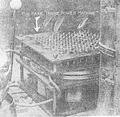
Here is the
atmospheric inductive coil which Mr. Perrigo made many
believe was the source of energy for his Reo roadster.
As a matter of fact, the electric motor never touched
hands with this machine. Storage batteries concealed
behind the seat did the work.
---
***Kansas
City Journal*** (August 11, 1927), p. 2
**"'Real Test' Is Perrigo's Aim"**
**But He Announces No
Time For Next Demonstration Before Engineers**
Other than that it
will be a "real demonstration before competent
engineers", H.E. Perrigo has announced no time for a
further showing of his "invention", which he declares
will take electrical power from the air.
Mr Perrigo apparently
was encouraged last night by the faith shown in him
yesterday when persons who have backed him refused to
attempt to prosecute him following assertations by
others that his invention is a hoax.
The test on which the
hoax charges are based, he declared, was not a test at
all. Those present, he said, did not give him an
opportunity to make a fair demonstration and one of them
was insulting and boisterous.
"No one who has helped
me in my invention", he said, "will lose money. Any
competent engineer will tell you sufficient storage
batteries to drive a heavy motor car 40 miles an hour
cannot be packed in a 28-inch space such as has been
charged in regard to my car."
Mr Perrigo was vague
as to the time the next demonstration will be given.
"I am willing", he
said, "to strip my car down so all its parts will be
revealed and let competent men judge whether the power
is derived from the source I claim."
---
[**https://www.nuenergy.org/uploads/perrigo.pdf**](https://www.nuenergy.org/uploads/perrigo.pdf)**Method and Apparatus for Accumulating
and Transforming Ether Electric Energy**
**Harry
Perrigo**
Department of
Commerce, United States Patent Office
To all persons to whom
these presents shall come, Greeting:
This is to certify
that the annexed is a true copy from the records of this
office of the Record for the United States Court of
Customs and Patent Appeals in the matter of the Pending
Application of Harry E. Perrigo, filed December 31,
1925, Serial Number 78,719, for **Improvement in
Method and Apparatus for Accumulating and Transforming
Ether**
**Electric Energy**.
In testimony where of
I have hereunto set my hand and caused the seal of the
Patent Office to be affixed, at the City of Washington,
this first day of March, in the year of our Lord one
thousand nine hundred and thirty (1930), and of the
Independence of the United States of America the one
hundred and fifty-fourth.
(Seal Patent Office,
United States of America.)
THOMAS E. ROBERTSON,
Commissioner of Patents.
Attest: D. E. WILSON,
Chief of Division.
Application of Harry E.
Perrigo. Serial No.78,719. Filed December 31, 1925.
To all whom it may
concern:
Be it known that I,
Harry E. Perrigo, a citizen of the United States,
residing at Kansas City, in the county of Jackson and
State of Missouri, have invented a certain new and
useful Method and Apparatus for Accumulating and
Transforming Ether Electric Energy, of which the
following is a complete Specification.
The existence of
electric waves in the ether has been shown by Hertz.
Electric disturbances in the atmosphere known as
"atmospherics" are known to produce noises in the
telephones of wireless, telegraph stations which in some
cases drown the signals being received. Ether wave
electric potential is also recognized in various forms
which are known to cause disturbances in the normal
operation of electric transmission and telephone
systems. These forms of electric wave possess potential
energy, or capacity for doing work and are commonly
described as a peculiar state or stress of a medium
called
ether.
The waves used in all
known systems of utilizing ether waves, as for example
in wireless telegraphy, are Hertzian waves artificially
propagated by means of electrical apparatus.
Except when manifest
as a force in electrical disturbances, the existing
ether waves with an unknown potential heretofore have
never been intercepted or collected and transformed into
forms of electric energy suitable for doing useful work,
previous to my invention and discovery of a method and
apparatus for the same. By my invention electric power
or energy is obtained for all purposes with out expense
other than that of my method and apparatus involved and
hereinafter described, for receiving and transforming
this electric energy.
The invention as
premised has for its objects:
First; To intercept
and collect from the general ether field electric wave
energy and to transform said electric energy into a form
of a distributable, measurable, electromotive force.
Second; To raise the
potential of these collected electric waves to a
pressure sufficient for applying said waves to practical
uses.
Third; A method of
intercepting and transforming an electromotive force
directly from the ether wave medium.
In describing the
procedure of carrying out my invention, and the details
of the apparatus, in one form of illustration, which
form has been fully demonstrated as being capable of
intercepting and transferring electric wave energy,
reference is now had to the
accompanying drawings,
in which **[Figure 1](#perr1)** is an
isometric view showing the electric wave interceptor or
collector mounted upon the electric transformer, also
showing the current distributing connecting wires
leading to a rheostat and to a series of incandescent
lighting lamps.
**[Figure
2](#perr2)** is an inverted plan view of the top or
positive plate of the wave interceptor, or collector,
showing the series of aerial terminals or contacts and
the broken or dead end or open circuit (hereinafter in
most cases called "broken circuit") connections with the
contacts.
**[Figure
2A](#perr2a)** is a transverse sectional view taken
through the collector aerial plate, and the terminal
contacts taken on line 2A--2A of **[Figure
2](#perr2)**.
**[Figure
3](#perr3)** is a plan view of the lower aerial plate
of the wave collector, showing the aerial terminal
contacts, and the broken circuit connections.
**[Figure
3A](#perr3a)** is a transverse sectional view of the
lower collector plate and the terminal contacts taken on
the line 3A--3A of **[Figure 3](#perr3)**.
**[Figure
4](#perr4)** is a perforated member made of insulating
material for containing the resistance coils between
the, upper and lower aerial plates, showing the top
member or cap of each resistance coil of the series.
**[Figure
4A](#perr4a)** is a transverse sectional view of the
insulating member shown in **[Figure 4](#perr4)**,
taken through the series or perforations lowest in
position in the member, on the line 4--4 of **[Figure 4](#perr4)**, and shows the
resistance coils in full lines.
**[Figure
5](#perr5)** is an enlarged detail side view of one of
the resistance coils which are located in the insulated
member shown in **[Figure 4](#perr4)**.
**[Figure
6](#perr6)** is an end view of one of the resistance
coils with the cap removed.
**[Figure
7](#perr7)** is a diagrammatic view of the electrical
connections between the resistance coils mounted between
upper and lower aerial plates.
**[Figure
8](#perr8)** is a transverse vertical sectional view of
the complete ether wave collector, taken on the line
8--8 in **[Figure 7](#perr7)**.
**[Figure
9](#perr9)** is a segmental plan view of the other wave
transformer, showing the coil windings.
**[Figure
9A](#perr9a)** shows one of the field coils in end
elevation.
**[Figure
10](#perr10)** is a vertical sectional view of the ether
wave transformer and the coil windings taken on the line
10--10 of **[Figure 9](#perr9)**.
**[Figure
11](#perr11)** and **[Figure 11A](#perr11a)**
are diagrammatic views of the two halves of the complete
coil windings of the transformer, show- the coil
windings, the cores of the windings not being shown,
these halves being in separate views to facilitate
showing the detail to a larger scale.
**[Figure
12](#perr12)** is a detail side view of the insulated
bridges in the air gap of the transformer, and the
reversed field windings, as they appear between the
bridges, except where marked "open".
Referring to **[Figure 2](#perr2)** and **[Figure 3](#perr3)**, the upper metal
plate 20+ and the lower metal plate 21- constitute the
aerials of my system of ether wave electric energy
collectors, and the terminal contacts 23 on the plate
20+ and the terminal contacts 24\* on the plate 21- are
shown connected diagrammatically by the electrical
conductors of the system. In the present illustration
are shown one hundred terminal contacts, this number
corresponding to the number of contacts 23, on the
aerial plate 20+, and a corresponding number of terminal
contacts 24\* on the plate 21-, the terminal contacts or
posts 23 and 24\* on the respective plates being spaced
equal distances from each other in rows of ten contacts
in the direction of the length and width of the
respective plates, and therefore have corresponding
registering positions with each other.
The system of electric
wave potential activity in my invention is embodied. in
the rapid changes in polarity of broken electric
circuits, and such a systematic arrangement of the
broken circuits as will cause the ether wave potential
to seek a path of lowest conductivity and not overload
any one conductor, and as an example of the operation of
the system the current path will be electrically traced,
and the transmission of the ether wave potential
followed from the source of collection to a definite
electric wave energy circuit. Let 20+ indicate, with its
terminal contacts, the positive source of permeability
and conductibility of recognized waves of ether, which
invariably act from a north to a south pole. To equalize
the general dispersion of these recognized waves of
ether for the purpose of effecting polarization of the
potentials of the ether waves, the ether waves are
broken and with the
change in direction of the wave potential, an electric
potential is produced, and the waves of ether are
conducted from contact to contact through a system of
wiring found, by discovery, and demonstrated to be
practical in operation, which produces electric energy
or electromotive force between the plates 20+ and 21-,
and which plates may be compounded or duplicated.
The system of broken
electric circuits which provides means of obtaining the
wave potential, is embodied in the system of wiring of
both plates 20+ and 21-, and in the transmission of
electric waves and change in polarity during their
transmission from contacts on the plate 20+ to the
contacts on the aerial plate 21-, the method of ether
wave conductivity being absolutely collective and
accumulative, showing that the difference of electrical
pressure as discovered in my system is the source of
electromotive force between the ether wave collecting
plates 20+ and 21-.
The system of wiring
of the plate 20+ will now be particularly described. It
has been found that fluctuations constantly exist in the
collective capacity of the aerial plates 20+ and 21-.
Following the diagram of winding on the inverted top
plate 20+ shown in **[Figure 2](#perr2)**,
the aerial terminal contacts are numbered in succession,
from one to ten, beginning at the right hand end of the
lower row, then for the next row from 11 to 20,
beginning at the right hand of the plate, and so on to
the upper row, which is numbered in the same direction
from 91 to 100.
The wire connections
on the top plate 20+, **[Figure 2](#perr2)**,
are through a conducting wire 1', one terminal of which
is connected with the contact 1, and the other terminal
with the terminal contact 2, and also from the contact
1, by the wire 1o, with contact 12.
Contacts 2 and 13 are
similarly connected. A similar connection extends from
contact 3 to contact 14. A similar connections are made
from contact 3 to contact 4, from 4 to 15, 5 to 6, 5 to
15, 6 to 17, 7 to 8, 7 to 17, 9 to 18, 9 to 20, 10 to
20, 11 to 12, 12 to 23, 13 to 23, 14 to 24, 15 to 16, 16
to 26, 19 to 29, 21 to 22, 22 to 31, 22 to 32, 23 to 24,
23 to 32, 24 to 34, 25 to 26, 25 to 35, 26 to 36, 27 to
37, 27 to 38, 28 to 29, 30 to 39, 32 to 41, 32 to 42, 33
to 34, 33 to 44, 36 to 37, 36 to 47, 38 to 48, 40 to 49,
41 to 52, 42 to 43, 45 to 54, 45 to 56, 46 to 47, 46 to
56, 47 to 57, 50 to 59, 51 to 52, 51 to 61, 52 to 53, 53
to 54, 55 to 64, 55 to 65, 56 to 57, 58 to 69, 60 to 70,
61 to 62, 63 to 64, 64 to 75, 65 to 76, 66 to 67, 66 to
76, 67 to 76, 68 to 77, 68 to 78, 68 to 79, 70 to 79, 71
to 72, 71 to 81, 72 to 81, 73 to 82, 73 to 84, 74 to 83,
74 to 85, 75 to 85, 75 to 86, 76 to 87, 77 to 78, 78 to
88, 78 to 79, 80 to 89, 81 to 91, 82 to 83, 83 to 92, 83
to 94, 84 to 95, 96 to 96, 86 to 97, 87 to 88, 87 to 98,
88 to 89, 88 to 98, 88 to 99, 90 to 99, 99 to 100, 92 to
93, 94 to 95, 95 to 96, 98 to 99.
The lower plate 21-,
as seen in **[Figure 3](#perr3)**,
includes the upwardly extending terminal contacts
precisely the same in number and position as upon the
plate 20+, the contacts being numbered in successive
order from 1 to 100 reversed as to the same characters
on the plate 21-, and beginning with the contact at the
lower row of contacts and at the left hand corner of the
plate 20+ and indicating said contacts 1-2-3-4 and so on
to 10, then beginning at the left and numbering from 11
to 21 and continuing in said order to the upper row
which are numbered from 91 to 100.
The wiring system of.
plate 21- is in broken circuits, as on the plate 20+,
the direction of the wires being traced from the
contacts at which the terminals of a broken circuit
ends, and which will now be tabulated, the ether wave
conducting broken circuit wires being charged from their
respective aerial contacts.
The wires are traced
on the plate 21-, from terminal contact 1, through a
straight wire 1x having one terminal
integral with the contact and its other terminal
connected directly with the terminal contact 11.
Then through like
conducting wires connections are made from contact 2 to
contact 3- and from contact 4 to contact 5-, contact 4
to 13, 5 to 6, 5 to 14, 7 to 8, 7 to 16, 8 to 9, 8 to
17, 8 to 18, 9 to 18, 10 to 20, 12 to 13, 13 to 22, l3
to 24, 14 to 23, 15 to 24, 15 to 25, 16 to 25, 17 to 26,
18 to 27, 19 to 38, 21 to 22, 24 to 34, 25 to 34, 26 to
35, 26 to 36, 26 to 37, 27 to 28, 28 to 29, 31 to 32, 31
to 41, 33 to 34, 35 to 45, 36 to 37, 37 to 48, 39 to 48,
40 to 50, 41 to 42, 42 to 43, 42 to 51, 43 to 44, 44 to
55, 46 to 47, 46 to 55, 46 to 56, 47 to 57, 48 to 59, 49
to 60, 51 to 62, 52 to 53, 54 to 63, 54 to 65, 56 to 57,
57 to 66, 58 to 68, 59 to 70, 61 to 72, 62 to 73, 63 to
64, 64 to 74, 65 to 66, 65 to 75, 66 to 67, 66 to 76, 67
to 77, 68 to 77, 69 to 80, 71 to 72, 71 to 81, 73 to 74,
73 to 82, 73 to 83, 74 to 84, 75 to 77, 76 to 86, 76 to
87, 78 to 79, 79 to 89, 81 to 82, 82 to 91 83 to 92, 84
to 93, 85 to 96, 85 to 94, 87 to 96, 87 to 97, 88 to 99,
90 to 100, 90 to 99. Where there is no outgoing wire
from one to another terminal contact, a broken circuit
occurs on both upper and lower plates.
Between the plate 20+
and plate 21- is an insulated member 22p
composed of a block of fibrous material in which are a
series of vertical openings 22x, these
openings being the same in number as the contacts on the
plates 20+ and 21- and in the same vertical positions,
so that there is an exact registration of openings and
terminal contacts. In these openings, are the series of
transmission resistance coils 25x, one of
which is shown enlarged, for illustration, in **[Figure 5](#perr5)** and **[Figure 6](#perr6)**.
These coils are
composed severally of a series of straight wires 25\*,
starting from a group of central wires around. which
other wires are wound, to form a body slightly less in
circumference than the openings 22' in the fibre block
22o. At the upper ends of the wires 25 is
attached a copper metal cap 25", and at the lower ends a
metal cap 25o. Around these wires, beginning
close to the top plate 25', fine insulated wire 26' is
connected at one end to one of the wires 25\*, and the
other end coiled about the collected wires 25\* winding
the wire to the right and its terminal secured at its
lower end to the same upright wire 25\* from which the
winding wire started thus forming a resistance coil, its
right hand winding of the coil, as seen in **[Figure 4A](#perr4a)** and **[Figure 5](#perr5)**, being upon coils in
which a resistance is interposed between the contacts
from a north to a south pole transmission of the
electric wave potentials, and these coils arranged in
the series being positioned, in the fibre block, as seen
in **[Figure 4A](#perr4a)**, the change
of the polarity of the wave potentials being through the
short circuit wires on the plates 20+, 21-, so that
wherever the short circuit occurs there is a rapid
change of polarity, the activity being greatest in the
coils of the least resistance.
Each resistance coil
is of a determinate length, and, as seen in **[Figure 4A](#perr4a)**, leaving a space of
the approximate distance from the cap plate 25" upwardly
to the line of the upper surface of the insulated member
22o co-equal with the posts or terminal
contacts 23" on the aerial plate 20+, and from the line
of the cap 25o on the lower end of the
resistance coils, to the lower surface of the insulated
member 22o similar spaces are provided, so
that when the upper and lower plates are assembled, the
posts or contacts 23\* on the upper plate 20+ enter the
spaces and come into contact with the caps 25" of the
respective resistance coils, and the terminal contacts
or posts 24\* enter the spaces beneath the lower caps 25o
of the respective resistance coils, and come into
contact therewith, as seen in the sectional view in **[Figure 8](#perr8)**, leaving between said
plates and the insulated member, passages 20x,
21x, for air gaps, respectively.
When thus assembled,
the groups of broken circuits of the plate 20+ contain
an electric potential opposed to the electric potential
contained in the group of broken circuits of the plate
21-. As these electric potentials are waves of impulse
from a south to a north pole intensity, and there is a
constant polarization and depolarization of the electric
ether waves, in other words, a pressure sufficient to
cause an electromotive force is discovered in the field
of the plates 20+, 21-.
A force existing in
space and collected therefrom, is the supreme power
residing in the electric potential, in an interrupted
path, with a rapid change of potentials, and has been
utilized in my invention, and its development is further
illustrated in **[Figure 7](#perr7)** of
the drawings, which show the plates 20+, 21-, in their
relative opposite positions, and with the contacts on
the respective plates 20+, 21-, in contact with the caps
of the respective resistance coils, the plate 20+ being
prismatic, showing the posts or terminal contacts on the
said plate, and broken, circuits on both plates 20+,
21-, the wire connections on the plate 21- being shown
in dotted lines.
Let the resistance
coils 25x, of the collector, in electrical
connection with the contacts 1-- 1 on the respective
plates 20+, 21-, indicate the lines of force passing
from contact to contact, the said plates 20+, 21-, with
their contacts being the terminals of serials through
which the electric ether is collected. The winding of
these coils are all similar and wound so that the flow
of the medium around the coils is from the upper
terminal of the coil, which is a north pole, and toward
the lower terminal or south pole.
The aerials collect
and transmit a flow of the ether or wave energy through
the conductors from what ever direction the potentials
of the ether are collected, and obtain a pressure of
sufficient force to effect a movement in the direction
of the least resistance from north to south, through the
resistance coils 1 to 100, transmitting a flow of the
ether medium or wave energy between all of the contacts
on the plates 20+, 21-, the flow being governed by the
lines of the least resistance, there following two
pressures between the north and south poles of the first
coil, the pressures being of opposite potentials, and
caused by the
opposite polarity of
the coils, and the electromotive force thus produced
between the plates 20+, 21-, is constant, one line of
force being broken by a line of force of a different
potential, and these forces all tending toward a common
polarity, while producing an electromotive force, in the
opposing resistances of these opposite wave potentials.
The method of obtaining electric energy as above
described, resides in reciprocal lines of force being
established by means of such broken circuits and
resistances, as are found by practical results to
produce an amperage of current or wave energy, and as
the action of
the collective broken
circuits with reversed polarities produce positive
electromotive force, the outgoing conductor 101, leading
from the aerial terminal contact 91 on the plate 20+ and
the outgoing conductor 102 from the aerial terminal
contact 100 on the aerial plate 21-, are connected to
the outer magnetizing coil windings of the ether wave
transformer, and electric energy is thus obtained.
The amperage of the
current or electromotive force collected or accumulated
by the ether wave collector is of low intensity, and for
the purpose of increasing this intensity, so that the
electromotive force may be brought up to a commercial
standard, this force is collected and regenerated, one
factor being supplemented by another, until the
electromotive force is built up to the standard of
electromotive force required; that is, the principle
within the collector (in the collection of the
electromotive force) is applied in a larger degree to
the ether transformer, the transformer being the adjunct
to the collector, one feeding a low potential to the
transformer, which increases this potential of the
collector to a higher potential, a dependency existing
in the ether transformer upon the collector.
This ether wave
transformer 103 is designed with a series of outer
magnetizing circuits, which are charged by electricity
from the collector, which energize series of inner cores
to a greater or less magnetic density, the inner cores
being insulated by an air gap from the outer magnetic
circuit, and electric current being generated in the
central coils, the current flowing through the various
coils responding upon the reaction in each circuit,
which reaction is least in coils 1 to 8 inclusive, **[Figure 11A](#perr11a)**, and greatest in
coils 25 to 32 inclusive.
The formation of these
central coils will now be defined with reference to **[Figure 9](#perr9)**, **[Figure10](#perr10)**, **[Figure 11](#perr11)**, and **[Figure 11A](#perr11a)** of the drawings,
**[Figure 11](#perr11)** and **[Figure 11A](#perr11a)** being read
together, the connections being shown in full lines at
the top of the coil, and in dotted lines at the bottom.
With reference to the
plan views of the enlarged segmental portions of the
coil, in **[Figure 9](#perr9)** and **[Figure 10](#perr10)** of the drawings,
respectively, it will be observed that these views show
the windings and the vertical wires or cores, while the
diagrammatic views **[Figure 11](#perr11)**
and **[Figure 11A](#perr11a)** omit these
vertical wires, in order to better illustrate the
controlling equalizing reactances, by
means of which the
electric output of the ether wave transformer is
increased to the full load required.
All of the windings of
the coil 103 are concentric with a central fibre core
piece O, at the center of the ether transformer, around
which the first series of vertical core wires 1' or
pins, as seen in **[Figure 9](#perr9)**
and **[Figure 10](#perr10)**, are
arranged in close order, and around said wires or pins
1` the first winding 1 is made, beginning at the top
surface of the fibre base 104 and winding the wire
circuitously to the right, around these vertical wires
or pins 1', building up the coil to the height of these
wires or pins 1' (see **[Figure 9A](#perr9a)**).
Outside of the winding
1 is placed another row of vertical wires or pins 2',
around which the coil winding 2 is built up from the
fibre base 104, to the height of said wires or pins 1'.
Then around said wire coil winding 2 is arranged a
series of vertical wires 3', and around these vertical
wires is made another coil winding 3, and thus continued
in the same manner from the coil winding 1, to coil
winding 32, outside of which winding is the air gap 32`.
Against this winding 32 are positioned the angle or
bridge plates 32o, which are arranged at
equal distances apart, in the direction of the
circumference of the coil 103-, and are insulated from
the coil winding 32-. These series of coil windings,
which are the transformer windings, are wound to the
right, as seen in **Figure 8A [Missing]**. In the
air gap, arc located the magnetizing coils arranged with
alternate north and south polarity, the air gap being
divided in the circumference of the transformer by
bridges, spaced equal distances apart, in which spaces
are magnetic coils 109, insulated from the bridges, as
seen in Figure 12.
The terminal of this
magnetizing coil, extends downwardly in the air gap to
the bottom and through the next bridge to the right and
the coil wound to form a reverse south pole winding S2,
which is indicated by the character S2, the
wiring being continued to the right, and in the
direction of the upper end of the coil through the next
bridge, and another coil formed, indicated by the
character N3, the wiring being so c6ntinued
to the right through the next bridge, and in succession
between the bridges to a point about one-half the
distance circumferentially of the ether transformer;
from the first open space mentioned, at which point is
seen a space marked "open" -- and from the bridge on the
far side of this space, a new coil begins, starting from
an upper portion of the bridge and forming a right hand
coil and the coil next to the bridge reversed. The coils
are then continued between the bridges, until the bridge
is reached on the left hand side of the open space first
mentioned.
Outside of the air
gaps, the excitation coil winding of the ether
transformer is placed, the first two coils 33 and 34,
being heavy, or of a larger gauge than the preceding
windings from 1 to 32.
The vertical core
wires outside of the coil 33 are also of increased size,
as seen in **[Figure 9](#perr9)**.
Continuing the winding of the excitation coils in a
series of eight windings from 33 to 40 inclusive, it
will be observed that the vertical core wires or pins
between the respective windings from 37 to 40 are of a
large capacity, several times larger in diameter than
the pins between the windings from 1 to 32.
The current from the
aerial plate 20+ of the collector is conducted through
the terminal 101 leading from said plate to a position,
as seen in **[Figure 11A](#perr11a)**,
and is connected with the coil 39 of the excitation
winding of the ether wave transformer. The conductor 102
leading from the collector plate 21- of the ether wave
transformer, is connected with the outer coil 40 of the
excitation winding of the ether wave transformer.
The coils of the
excitation circuits are connected in series as follows:
The outer coil 40 is connected by the conductor 40' with
the coil 34, and the coil 39 through the conductor 39`
with the coil 33. The coil 38 is connected by the
conductor 38 with the conductor 34. The coil 37 is
connected through the conductor 37' with the magnetic
coil 33. The coil 36 is connected through the conductor
36' with the coil 33, and the coil 35 is connected by
the conductor 35' with the coil windings 34, thereby
connecting all of the excitation coil windings from the
inner to the outer coil windings 33 to 40 inclusive.
One end of an
insulated bus rod 41 is connected with coil 33 of the
excitation circuits, and the other end extends above and
is connected to coils 1 to 8. Bus rod 42 is connected to
coil 34 and extends to the bottom of coils 1 to 8. In a
like manner, bus rods 43 and 44, 45 and 46, 47 and 48,
are connected to their respective groups of coils, as
shown in **[Figure11](#perr11)** and **[Figure11A](#perr11a)**.
Between coils 32 and
33 is provided a space for the poles the ether wave
transformer, the said space in this case being separated
into twenty-six divisions, although any even number of
poles might be used. Each pole space is separated by
non-magnetic bridges 32o, two of the said
spaces lying upon opposite sides of the transformer, and
upon opposite sides of a line intersecting with the axis
of said transformer, being marked "open". The other
twenty-four pole spaces arc in this case divided into
four groups of six each. The first space adjoining one
of the spaces marked "open" contains an iron core wound
with an excitation winding, as further herein
illustrated, the excitation winding being wound to
produce magnetic lines of force from north to south, and
in the next space to the right there is a similar core
wound to produce magnetic lines of force from south to
north, and so on in succession, the sixth space having a
coil marked S6, or south-sixth it being
premised that these coils are independent of, and
insulated from, the bridges and located as shown in **[Figure 12](#perr12)**, in which one of
the bridges adjacent the space marked "open" is shown in
detail, comprising a vertical non-magnetic web extending
from the line of the top of the ether wave transformer
to the insulated base 104 and provided with the flanges
106- and 107, both insulated from the respective coils
32 and 33 on opposite sides of the pole space.
The system of wiring
involved in the aforesaid excitation winding in one
completed circuit may be electrically defined as the
magnetic field excitation and regulation circuit, which
can be traced as follows: Beginning with bus coil 33,
the bus rod 41 is shown connected to each of the eight
terminal contacts marked by the characters Pl,
P2, P3, P4, P5,
P6, P7 and P8, which
are connected respectively, to each of the coils one to
eight of the ether wave transformer, and the lower
terminals of each of these coils are connected in
reverse order to contacts marked N, from which points
the circuit divides into two paths, one leading through
field coils, and one to bus rod 42, which is connected
at its outer end to the bus coil 44 from contacts marked
P1, P2, P3, P4,
P5, P6, P7 and P8,
the group of connections 82 lead to terminals
86 the field excitation windings successively
on fields S6,
N5, S4, N3, S2
and N1, from which the winding terminates,
and is brought out at the bottom and connected at 84
to a series of eight wires, the group being indicated by
the character 83 and shown in dotted lines,
these eight wires terminated at contacts marked N, from
which points the circuit is completed through bus rod
42, to bus coil 34, specifically the insulated field
coils to the right of the space marked "open", and near
the bus rod 42, and are connected with the terminal of
an electric conducting wire 85 (see **[Figure 12](#perr12)**), forming in said
space a right hand coil N-1, from which the end of tile
wire emerges from the lower portion of the coil, and is
extended through an insulated opening 111, in the web of
the bridge supporting plate 110, --thence extended
upwardly within the next space of air gap to the like
coil in said space, and through opening at the upper end
of said plate, thence to opening in the opposite plate,
forming a left hand coil S-2, and so continued
downwardly, the winding being to the left, changing the
polarity of the coil. At the lower end of plate 110 the
end of the wire emerges, and is then extended through an
insulated opening in the next bridge supporting like
coils, the winding of the coil in the next space being
similar in which the windings are wound to the right,
and in the next space to the left, and so continued,
these coils being designated in **[Figure
11A](#perr11a)** as N1 (north 1), the next S1
(south 1). the next N^2, the character numerals 1 to 6
indicating the spaces of the air gap, the last space in
the series of six coils being a south pole winding,
indicated by reference numerals S-6. In this latter
magnetic coil, the wire is extended upwardly as
indicated at 86, and with said wire is
connected the terminal contacts of the group of
conducting wires 82 leading from the terminal
contacts on the inner end of the bus rod 41- hence
completing the winding of the divisional six spaces of
the twenty four, and from this connection 86
the wire is extended through an insulated opening into
the first divided space of the next series of six spaces
of the air gap, where the end of the wire is given a
right hand, winding, and the magnetic coils thence
continued as before described.
The connections upon
the other portions of the coil are as follows:
Upon the lower side of
the generator coil, and upon the same radius as the bus
rod 41, is a bus rod 43, which is connected at its outer
end with excitation coil 34 of the transformer and its
inner end with the respective coils 9-10-11-12-13-14-15
and 16 of the ether transformer. With this bus rod at
the points of connection of said rod with the aforesaid
coil windings, are connected the terminal contacts of a
group No, of wires 87, which are
connected with the end of the wire in the space past
which the bus rod 43 extends, and a north pole magnetic
winding formed in said space.
The next bus rod 44,
above the last space of the divided air gap of the next
series of six spaces, is connected with the pole of the
magnetic coil winding 33 of the transformer, at one end,
and at the other end with the poles of the coils 9 to 16
inclusive. With the bus rod at the points of connection
with the respective coils are connected the terminal
contacts P16 of a series or group of
conducting wires 85 from 9 to 16 inclusive
the outer numerals being connected with the south pole
windings in the space of the air gaps below said bus
rod.
With the group of
terminal contacts N10, on the bus rod 43, are
connected the upper ends of a group of conducting wires
88, the upper ends of the wires being
extended upwardly, and connected in an inverse order
with the group of contacts P16. The next bus
rod or wire is positioned upon the other half of the
ether transformer, and upon the lower side, and
indicated by the reference numeral 45. This bus rod is
connected at its outer end with the pole windings 34,
and at its inner end with the coil windings 17 to 24
inclusive, and with which windings are connected the
terminal contacts 20 of a group of eight wires leading
to and connected with the north pole magnet winding wire
in the space past which the bus rod extends.
The next bus rod 46 is
above the top of the transformer, and is connected with
the pole of the excitation coil winding 33 of the
magnetic circuit of . the transformer, and at its inner
end with the series of coils 17 to 24 inclusive, with
which bus rod are connected the series of terminal,
contacts P24 of the group of eight wires P25
leading to and connected with the south pole windings in
the sixth space of the divided air gap over which the
bus rod 46 extends.
With the terminal
contacts N20 are connected the lower ends of
the series of wires N21, the other, ends
being extended upwardly and connected in inverse order
with the terminal contacts 24.
The next bus rod 47 is
extended beneath the coils of the transformer, the outer
end being connected with the pole of the coil 34, and
its inner end connected with the eight coil windings 25
to 32 inclusive.
With the bus rod 47,
above these coil windings, are connected the terminal
contacts of a group of eight wires 22, the other ends
being connected with the coil winding in the first space
of the air gap, past which the bus rod 47 extends.
The next bus rod 48
extends upon the top of the transformer, and extends
over the sixth space of the air gap. In the fourth
quarter of the circumference of the transformer, and is
connected at its outer end with the pole or the coil 33
of the magnetic circuits, and at its inner ends, with
the poles of the eight to coils 25 to 32 inclusive.
With the said bus rod
are connected the terminal contacts of a series or group
of eight wires P26 connected with the south
pole coil winding in the sixth space aforesaid, and with
the contact terminals of the group of wires N22,
are connected the ends of a group of eight wires P27,
their upper ends being connected in reverse order with
the terminal contacts of the wires P26 on the
respective coils 32 to 25 respectively.
The description being
now completed of the magnetic excitation coil windings,
and of the magnetic field coil wire regulation, which
latter it will be observed are arranged for the
excitation of any portion of the ether transformer, from
the magnetic circuit to the coil windings 1 to 32 from
the consumption of the current obtaining the full self
induction action or current generating capacity of the
transformer, the magnetic circuits being traced in like
manner as first described.
The ether wave
collector, as arranged in conjunction with the ether
wave transformer, before described, and for practical
operation, is as seen in **[Figure 1](#perr1)**,
the lower plate 21 of the collector resting upon
insulating cross bars 113-116 which extend across the
top of the transformer 103. In this position of the
collector, it will be seen that the current conducting
wires are in the form of bars, the upper end of the bar
118 being connected with the plate of the collector, and
the lower end extended downwardly and insulated from
plate 21 and bent inwardly and thence downwardly into
contact with the excitation winding of the outer
excitation coil 40 of the magnetic circuits.
The feed wires for
current distribution are connected with the coils of the
magnetic excitation circuit, like terminal of one wire
indicated by the character 117, being connected with the
pole of the coil 33 of the transformer 103, opposite the
space of the divided air gap marked "open" and first
alluded to in the description of the first series of six
spaces of the air gap of the transformer.
The other wire 118 has
its inner terminal connected with the coil winding 34 of
the magnetic field upon the reverse portion of the
transformer.
The outer portions of
these feed wires 117 and 118 connect with a double pole
switch 120, which makes contact with the conducting
wires 121-122 of the rheostat controller 124.
With the rheostat are
connected the inner terminals of the conducting wires
125 and 126, the outer terminals being connected in
parallel with the lamp circuit upon the socket board
127, in, which are shown the incandescent lamps 128 in
series, in the incandescent circuit.
It is obvious that the
outgoing feed wires may be connected with the fields of
a motor and electric energy transmitted at high and low
velocity as the load of the motor increases, or vice
versa, as the increase in the number of incandescent
lamps are increased, to excite the magnetic circuits of
the transformer, the efficiency of which will now be
described in connection with the collector of ether wave
medium.
The electromotive
force of the current from the ether wave aerial
collector flows or is conducted by the conductors 101
and 102, whose terminals are connected with the aerial
plates 20+, 21-, respectively, and also with the coil
windings 39 and 40, respectively, of the ether wave
transformer. The current flowing in the magnetic circuit
of the coils energizes conductors 39', 40', magnetizing
coil windings 33 and 34 respectively, and these coils 33
and 34 energize the magnetic coils 37 and 38, through
the conductors 37', 38' respectively, and the coils 35
and. 36 are energized through the conductors 35', 36'
respectively, from the coils 33 and 35 respectively, and
the whole magnetic circuit from 33 to 40 are energized.
The current then flows through the bus rods to the coil
near the center of the transformer which has the least
resistance, which as indicated the first coil, outward
from the insulated core piece O.
The current generated
and flowing through the bus rod is generating an
electromagnetic force in the magnetic circuit.
The coil energized has
a return through the bus rod 43- to the magnetic circuit
to its bus coil 34, and the electromotive lines of force
are impeded by changes in the lines of force which cause
fluctuations in the change of polarity.
The double pole switch
120 being thrown to bring into contact the outgoing feed
wire terminals of the feed wires 117-118, with the
conducting wires 121-122 of the rheostatic controller
124, the current of the required force is transmitted by
the conductors 125-126 to the series of incandescent
lamps 128.
The transformer now in
use by myself for service lighting is now connected with
a lighting circuit now in operation.
The electromotive
force of the transformer being increased, by the amount
of load, increases the flow of the current through the
first magnetizing coil of the transformer from 1 to 8,
setting up new lines of electromotive force, the
potentials of which in moving toward the lines of the
least resistance, meet a change in lines of force
through the reversed group of wires 84, at
the same time generating a larger magnetic electromotive
force in a reverse movement by the path of the bus rod
41, which being met by an increase of the lines of
magnetic force from the magnetic coils, acts to control
the movement of the current, while generating in the
collision of these lines of force a higher electromotive
force, involving the magnetic coils in the spaces from 1
to 6 inclusive, of the air gap, the current now flowing
through the magnetic coil during its flow from the group
of conductors 83, to the conductors in the
space S6 in the first series of six spaces of
the air gap, the current flowing through the magnetic
wiring by the conductor 85, in the space
marked N1, thence through the magnetic
winding S2 in the next space, thence through
the magnetic windings N2 in the next space,
thence through to magnetic winding S4 in the
next space, thence through the magnetic winding N5in the next space, thence through the magnetic
windings N6 in the next space, at which
point, the current whose fluctuations have been
regulated in rapid changes of polarity, with increased
electromotive force, flows with an inductive force
through the bus rod to energize the series of coils from
1 to 8, it being observed that in my transformer the
electromotive force is being from magnetizing coil 1 to
32 respectively until an increased load is thrown on the
transformer, increasing the magnetic lines of force of
the coils of the transformer, when the inductive force
is set up in the magnetic circuits through conductors
37', 35', involving a generation of current which finds
its path through bus rod 44, and bringing into circuit
the next 8' coils of the transformer where the lines of
force in the correction of the poles of the group of
wires 81 are subjected to a change of
polarization and depolarization through one or more of
the wires 88, setting up additional
electromotive force, its fluctuations being made
constant through the magnetic field coils in the spaces
of the air gap from 1 to 6 in the next quarter division
of the transformer, and as the load further increases so
as to involve the magnetic circuits 33 and 35, the flow
of the current is inducted through the conductors 35x,
36', through the bus rod 46, taking the electromagnetic
force from the excitation from all the coils of the
transformer, whose potentials follow the group of
conductors which lead to the next series of coil
windings 16 to 24, flowing through the reversely
connected group of wires N21, and is then
conducted through the series of magnetic coils in the
nex t series of coils respectively.
As the load increases,
the Principal magnetic coils shown in heavy lines in **[Figure 11](#perr11)** and **[Figure 11A](#perr11a)** in the last
distribution of current, flows from the dense coil 32,
energizing bus rod 48, and also energizing the series of
eight coils of the transformer from 1 to 32 inclusive,
the current flowing through the reversely connected
conductors P27 through magnetizing field
coils, cutting the line of force and creating an
electromotive force the current flowing through the
fourth division of the six spaces of the air gap, and
the magnetizing field coils in said series, in which the
fluctuations of the current are made constant and the
full distribution of the current is now attained from
each portion of the transformer, in which portions,
while the electromotive force is increased to meet the
demands of the load, a constant regulation is being
effected in the excitation coils and through the
magnetizing field coils, impeding the lines of least
resistance which are afforded a compensating resistance
in proportion to the load cut in and out through the
rheostatic controller, hence, as the electromagnetic
force of the transformer is increased to supply the
electromotive force required, the accumulation of the
ether waves in the collector produces an electromotive
force of undiminished quantity, this result being a new
discovery of far reaching benefit to mankind, involving
as it does the inceptive potency of electric energy for
all, purposes, evolved from the general ether wave field
of electric medium by me.
Having fully described
my invention, what I now claim as new and desire to
secure by Letters Patent, is:
1. The production and
generation of an electromotive force from the
accumulation of the ether waves of an unknown potential,
from the general field of ether wave electric medium.
2. The production and
generation of an electromotive force, from the
accumulation of the potentials of ether waves of
electric medium, and their polarization into
electromotive force constant.
3. A source of
electromotive force, comprising an inductive
polarization and depolarization of the pulsating waves
of ether, from the ether wave potential of the ether
wave electric medium.
4. The production and
generation of an electromotive force, consisting of the
accumulation of the ether waves of the general electric
ether wave medium, and changing their potentials in the
paths of broken circuits of opposite polarity, and
polarizing and depolarizing the wave potentials and
subjecting the energized potentials to a transmission
through magnetic circuits.
5. A source of
electric motive force, comprising the inductive ether
wave potentials of the ether wave medium, whose
potentials are changed through resistances in their
paths, and then polarized and depolarized in
transmission.
6. The method
described of producing an electromotive force,
consisting in collecting the ether waves from the
general field of electric medium, their potentials
changing within broken circuits, then through polarized
resistances.
7. The method
described of producing an electromotive force,
consisting in collecting the ether waves from the
general field of electric medium, changing their
potentials, transmitting them within broken circuits,
polarizing and depolarizing the potentials and through
polarized resistances in magnetic circuits.
8. The method herein
described of producing an electromotive force,
consisting in collecting and accumulating the ether
waves from the general field of electric ether wave
medium, changing their potentials and transmitting these
potentials within broken circuits, polarizing and
depolarizing these potentials in a transmission through
polarized resistances in magnetic circuits of reversing
polarities.
9. The method herein
described of producing an electromotive force constant,m
consisting in collecting and accumulating the ether
waves from the general field of electric ether wave
medium, changing their potentials and transmitting these
potentials within paths of broken circuits, changing
their potentials and polarizing and depolarizing these
potentials and transmitting them through polarized
resistances, thence through magnetic circuits in which
circuits the polarities are changed according to the
electromotive force.
10. The method and
apparatus herein described, for collecting from the
general ether field, of electric medium, of electric
ether waves or ether in an accumulative, distributable,
measurable, electromotive force.
11. The method. and
apparatus herein described, for collecting from the
general ether field of electric medium of the wave
potentials, and breaking up the lines of force of these
potentials to produce an electromotive force.
12. The method and
apparatus herein described for collecting and
accumulating from the general field of electric medium
of ether waves of unknown polarity and converting these
waves into lines of electromotive force of constant
polarity.
13. The method and
apparatus herein described for collecting and
accumulating from the general field of electric medium,
of ether waves of unknown polarity from aerials of
opposite polarity, transmitting these waves through
broken conductors in groups of broken circuits in
electrical contact with the aerials, then through
polarized resistances in electrical contact with the
conductors in the broken circuits.
14. The method and
apparatus herein described for collecting and
accumulating from the general ether field of electric
medium of the ether waves, consisting in establishing a
conductivity of the wave medium between aerial
conductors in parallel, and conducting the ether wave
from conductors through groups of broken circuits in
electric connection with the terminals of the aerials,
and interposing polarized resistances between the
terminals of the aerial conductors.
15. The method and
apparatus herein described for collecting and
accumulating from the general ether field of electric
medium of unknown polarity, of ether waves of
electromotive force, consisting in conducting the lines
of force of the ether electric waves through aerials and
within groups of broken circuits, and breaking up the
lines of force, then reversing the polarity of these
potentials through the medium of polarized resistances.
16. The method and
apparatus herein described for collecting and
accumulating from the general ether field of electric
medium, of an amperage of electromotive force, and
increasing its lines of force in a transformer of
magnetic lines of force.
17. A collector of
ether electric waves, consisting of aerial conductors,
and a group or groups of wave polarizing and
depolarizing broken circuits leading therefrom, and
polarized resistances so related to the broken circuits
as to break up the potentials of the ether medium.
18. A collector of
ether electric waves, consisting of aerial conductors,
and a group or groups of wave polarizing and
depolarizing broken circuits in wave transmitting
connection with the terminals of the aerial conductors,
and polarized resistances in the path of the electric
medium at the terminals of the aerials.
19. A collector of the
ether electric waves, consisting of aerial conductors,
and terminal contacts and broken wave group or groups of
conductors polarizing and depolarizing connected with
the terminal contacts.
20. A collector of
ether electric waves, consisting of aerial conductors of
the potentials of the electric waves, and opposing group
or groups of wave polarizing and depolarizing broken
conductors, in wave transmitting connection with the
terminals of the aerial conductors, and polarized
resistances connecting the group or groups of broken
circuits and insulated therefrom.
21. A collector and
accumulator of the ether electric waves, consisting of
wave inductive aerial plates, and terminal contacts in
opposite wave transmitting positions.
22. A collector and
accumulator of the ether electric waves, consisting of
wave inductive aerial plates, each plate having a series
of terminal contacts in registering positions, and
polarizing and depolarizing conductors in broken
circuits carried by the terminal contacts on each plate, and wave
transmitting polarized resistances connecting the
registering contacts.
23. A collector and
accumulator of the ether electric waves, consisting of
separate wave inductive aerial plates, and a series of
terminal contacts on each plate in registering positions
to each other respectively, means for insulating one
plate from the other, and a group or groups of
conductors in broken circuits on each plate, in wave
transmitting connection with the terminal contacts, and
polarized resistances connecting the contact on the
other plate.
24. A collector and
accumulator of the ether electric waves, consisting of
separate wave inductive aerial plates, and a series of
terminal contacts on each plate, an insulating member
between the said plates provided with openings
registering with and admitting said terminal contacts,
polarized resistance coils in said openings connected
with the respective contacts on the separate plates, and
wave polarizing group or groups of broken conductors on
said terminal contacts.
25. An apparatus for
the collecting, accumulating and accreting, the ether
electric wave energy, comprising inductors of the ether
electric waves, circuit breaking polarizers and
depolarizers of the electric waves, potentials changing
elements connecting the broken circuits, and magnetic
circuits, and polarizing and depolarizing current
transmitters in the magnetic circuits.
26. A collector and
accumulator of the ether electric waves, and a
transformer of increased energy of electromotive force,
from the amperage of wave energy transmitted from the
accumulator.
27. An ether wave
transformer of electromotive force, comprising magnetic
circuits, and polarizing and depolarizing circuits
controlling the magnetic circuits.
28. An ether wave
transformer of electromotive force, and magnetic
circuits of increased activity without the main body,
and an air gap between, and polarizing and depolarizing
circuits connecting the poles of the magnetic circuits
of the main body, with
the poles of the
magnetic circuits of the outer body, and electrically
controlled thereby.
29. A collector and
accumulator of the ether electric waves, and magnetic
circuits energized by the polarized and depolarized
ether waves from the accumulator.
30. An ether wave
transformer of electromotive force, comprising an
internal body of magnetic circuits, and an external body
of magnetic circuits of increased magnetic intensity to
that of the internal body, and an air gap between,
conductors connecting the magnetic poles of the terminal
body with the magnetic poles of the outer body, and
groups of polarizing and depolarizing circuits
connecting the conductors of these poles with each
other, and polarized, resistances in the air gap
connected with the polarizing and depolarizing circuits.
31. An ether wave
transformer of electromotive force, comprising a series
of internal magnetic circuits, and a series of external
magnetic circuits, and an air gap between, conductors
connecting the poles of the external magnetic circuits
with the poles of the internal magnetic circuits in
progressive degrees of electric induction, and
polarizing and depolarizing circuits connected with the
terminal contacts of the conductors with the poles of
the magnetic internal circuits with each other in
reverse order, and conductors leading from said poles to
the air gap and polarized resistances connected with the
polarizing and depolarizing circuits within the air gap.
32. An ether wave
transformer of electromotive force, comprising an
internal body of magnetic circuits, and an external body
of increased magnetic intensity, to the internal body,
and having an air gap between, insulated means
connecting the internal and external bodies of magnetic
circuits, and conductors connecting the poles of the
internal and external magnetic circuits in progressive
degrees of electric induction, and polarizing and
depolarizing circuits connecting the conductors from the
poles of the magnetic circuits in series, and series of
polarizing and depolarizing circuits connecting said
series of conductors in reverse order, and polarized
resistance coils in the air gap insulated from the
magnetic circuits and connecting electrically the series
of reversed polarizing and depolarizing circuit from the
magnetic circuits.
33. The herein
described method of producing electromotive force
between the poles of a transmission resistance coil.
34. The herein
described method of producing electromotive force from
the ether waves of electric medium between the lines of
force passing through the poles of a transmission
resistance coil.
35. The herein
described method of producing electromotive force from
the aerials of conductors of ether wave electric medium,
by changing their potentials during the transmission of
the lines of force through wave transmission
resistances.
36. The herein
described method of producing electromotive force
conducted through the aerials of the ether wave electric
medium consisting in changing their potentials through
broken conductors in contact with the aerials and during
transmission of the lines of force through wave
transmission resistance coils.
In witness whereof I
hereunto affix my signature:
**Harry E. Perrigo**
---
**Figure 1:**Isometric view showing the electric wave
interceptor or collector mounted upon the electric
transformer, also showing the current distributing
connecting wires leading to a rheostat and to a series
of incandescent lighting lamps.
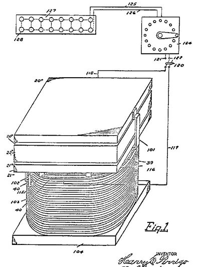
**[CLICK
HERE FOR ENLARGEMENT](p1xx.jpg)**
---
**Figure 2:**
Inverted plan view of the top or positive plate of the
wave interceptor, or collector, showing the series of
aerial terminals or contacts and the broken or dead
end or open circuit (hereinafter in most cases called
"broken circuit") connections with the contacts.
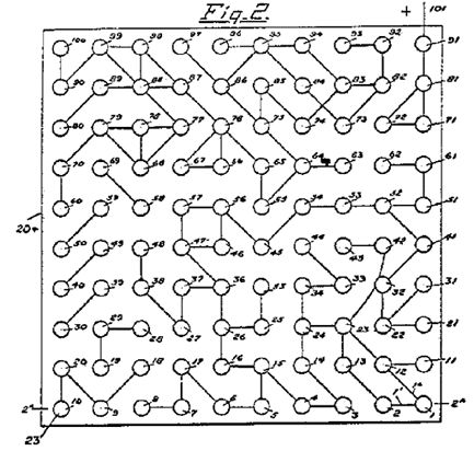
**[CLICK
HERE FOR ENLARGEMENT](p2xx.jpg)**
---
**Figure 2A:** Transverse
sectional view taken through the collector aerial
plate, and the terminal contacts taken on line 2A--2A
of Figure 2.

---
**Figure 3:** Plan view of the lower
aerial plate of the wave collector, showing the aerial
terminal contacts, and the broken circuit connections.
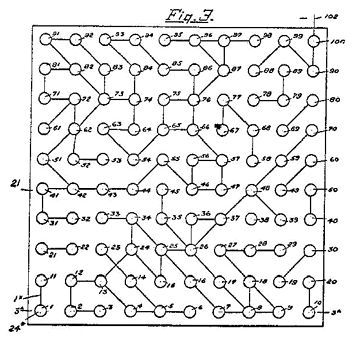
**[CLICK
HERE FOR ENLARGEMENT](p3xx.jpg)**
---
**Figure 3A:** Transverse
sectional view of the lower collector plate and the
terminal contacts taken on the line 3A--3A of Figure
3.
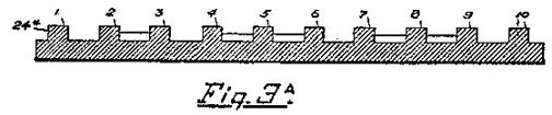
---
**Figure 4:** Perforated
member made of insulating material for containing the
resistance coils between the, upper and lower aerial
plates, showing the top member or cap of each
resistance coil of the series.
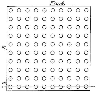
---
mso-margin-bottom-alt:auto;margin-left:1.0in">**Figure 4A:** Transverse
sectional view of the insulating member shown in
Figure 4, taken through the series or perforations
lowest in position in the member, on the line 4--4 of
Figure 4, and shows the resistance coils in full
lines.
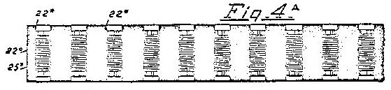
---
mso-margin-bottom-alt:auto;margin-left:1.0in">**Figure 5:** Enlarged
detail side view of one of the resistance coils which
are located in the insulated member shown in Figure 4.
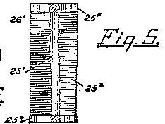
---
**Figure 6:** End
view of one of the resistance coils with the cap
removed.
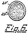
---
**Figure 7:**
Diagrammatic view of the electrical connections
between the resistance coils mounted between upper and
lower aerial plates.
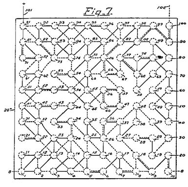
**[CLICK
HERE FOR ENLARGEMENT](p7xx.jpg)**
---
**Figure 8:**Transverse vertical sectional view of the complete
ether wave collector, taken on the line 8--8 in Figure
7.
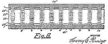
---
**Figure 9:**
Segmental plan view of the other wave transformer,
showing the coil windings.
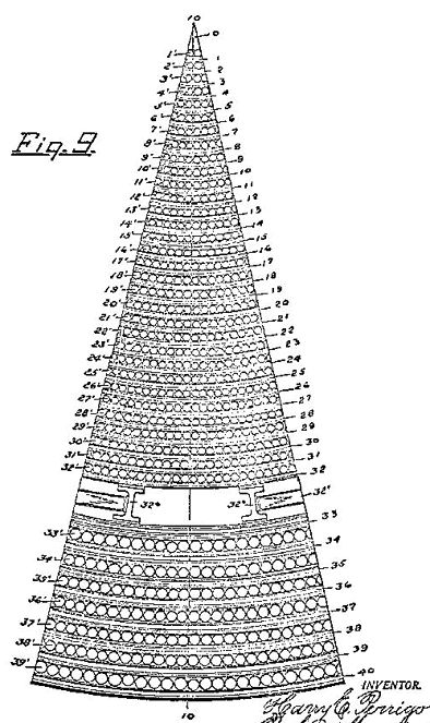
---
mso-margin-bottom-alt:auto;margin-left:1.0in">**Figure 9A:** One of
the field coils in end elevation.
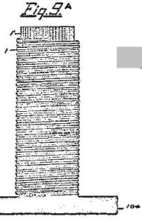
---
mso-margin-bottom-alt:auto;margin-left:1.0in">**Figure 10:** Vertical
sectional view of the ether wave transformer and the
coil windings taken on the line 10--10 of Figure 9.
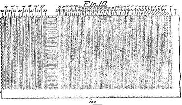
**[ENLARGEMENT](p10xx.jpg)**
mso-margin-bottom-alt:auto;margin-left:.5in;text-align:center">
---
**Figure 11:**Diagrammatic
views of the two halves of the complete coil windings
of the transformer, show- the coil windings, the cores
of the windings not being shown, these halves being in
separate views to facilitate showing the detail to a
larger scale.
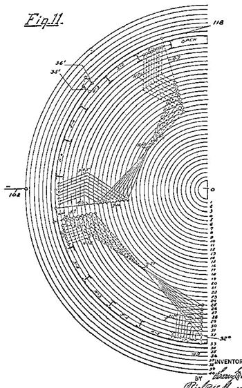 **[ENLARGEMENT](p11xx.jpg)**
---
**Figure 11A:** Diagrammatic
views of the two halves of the complete coil windings
of the transformer, show- the coil windings, the cores
of the windings not being shown, these halves being in
separate views to facilitate showing the detail to a
larger scale.
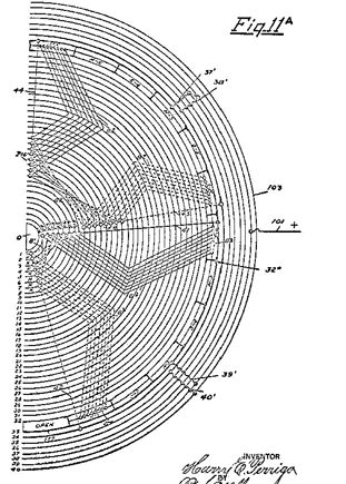
**[ENLARGEMENT](p11axx.jpg)**
---
**Figure 12:** Detail side view of the
insulated bridges in the air gap of the transformer, and
the reversed field windings, as they appear between the
bridges, except where marked "
**[ENLARGEMENT](p12xx.jpg)**
---
[**https://www.youtube.com/watch?v=0SrZf4WXc5U**](https://www.youtube.com/watch?v=0SrZf4WXc5U)**What// exactly did Harry E. Perrigo
Have? Double M Innovations**The mystery of Harry E. Perrigo, and his free energy
devices. From 1916-1927 Harry Perrigo had devices
that could light his whole house, and power an electric
car. He claimed he was pulling electricity right
out of thin air, using various designs of
antennas. Then; he lied about a battery that was
found in his car, and he was declared a fraud.
What he did have, was never discovered, and is still a
mystery.
[**https://www.youtube.com/playlist?list=PL2xxHk8R-R09y2FIo8i94R8sU8UDH-FFt**](https://www.youtube.com/playlist?list=PL2xxHk8R-R09y2FIo8i94R8sU8UDH-FFt)**Harvesting Antenna Energy // Double M
Innovations**[**https://kchistory.org/islandora/object/kchistory%3A66701**](https://kchistory.org/islandora/object/kchistory%3A66701)**Harry E. Perrigo** Photos, illustrations, and information on Harry
Perrigo, a local inventor of a "free energy" device in
the 1910s-1920s turning out to be a hoax. Energy source
of "invention" supposedly "from thin air" or from "ether
waves" but in actually from a hidden motor.
---
[**https://www.electronicsweekly.com/blogs/mannerisms/fable/fable-18-2023-11/**](https://www.electronicsweekly.com/blogs/mannerisms/fable/fable-18-2023-11/)**Fable: The Guy Who Tapped Ether Waves For
Electricity**
98 years ago a patent application was filed by an MIT
graduate from Kansas City, Missouri, which stated:
Except when manifest as a force in electrical
disturbances, the existing ether waves with an unknown
potential heretofore have never been intercepted or
collected and transformed into forms of electric energy
suitable for doing useful work, previous to my invention
and discovery of a method and apparatus for the same. By
my invention electric power or energy is obtained for
all purposes without expense other than that of my
method and apparatus involved.
Here is the guy with his apparatus which he had
previously demo-ed before the US Congress.
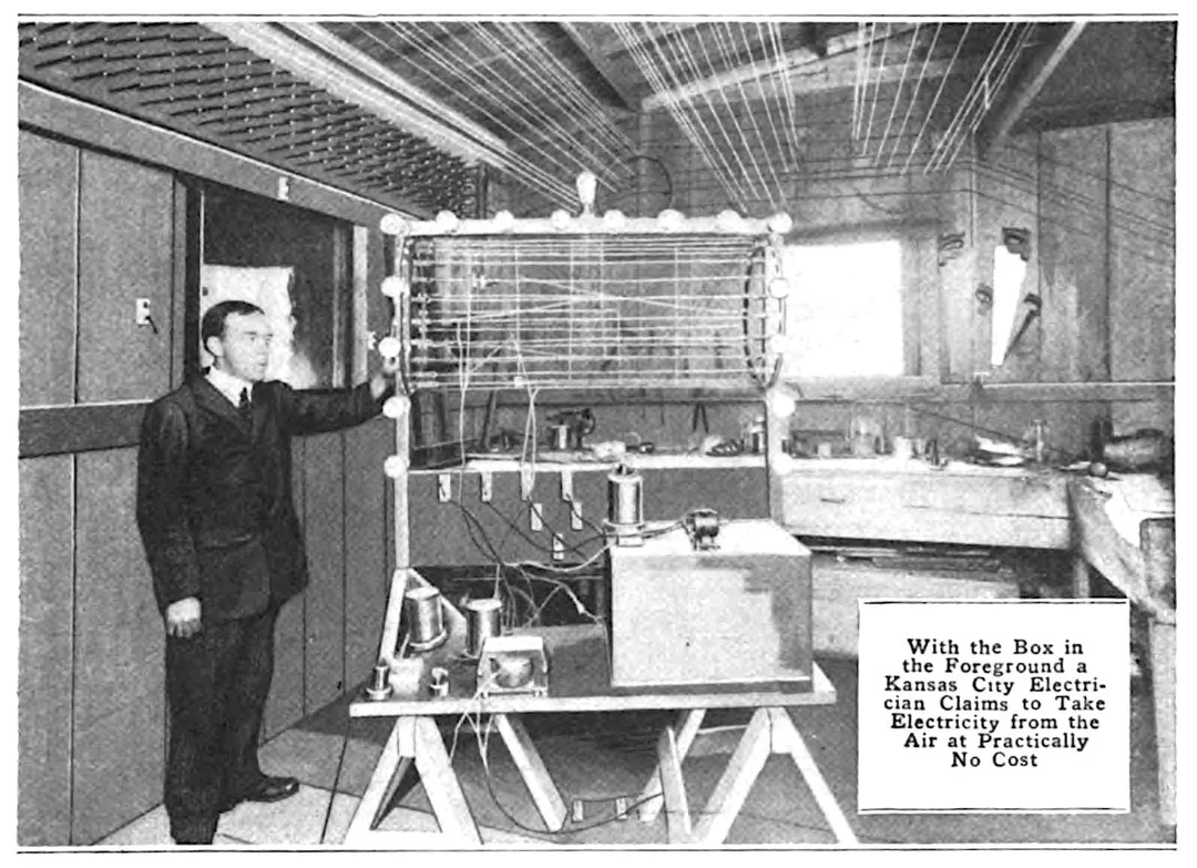
However
Congress refused funding, the US Patent Office rejected
the patent application and, instead of being a source of
free energy, investigators found that the apparatus
contained a hidden motor battery.
Moral: Hope Springs Eternal
---
[**https://casetext.com/case/in-re-perrigo**](https://casetext.com/case/in-re-perrigo)**In re Perrigo**
Court :Court of Customs and Patent Appeals
Date published: Apr 29, 1931
Opinion
Patent Appeal No. 2723.
April 29, 1931.
Appeal from the Board of Patent Appeals.
Application for patent by Harry E. Perrigo. From a
decision rejecting the application, the applicant
appeals.
Affirmed.
T.A. Hostetler, of Washington, D.C., for Commissioner of
Patents.
Before GRAHAM, Presiding Judge, and BLAND, HATFIELD,
GARRETT, and LENROOT, Associate Judges.
GARRETT, Associate Judge.
The application in this case relates to "Method and
Apparatus for Accumulating and Transforming Ether
Electric Energy," and embraces 36 claims of which
numbers 1, 15, 21, and 32 seem fairly representative:
"1. The production and generation of an electromotive
force from the accumulation of the ether waves of an
unknown potential, from the general field of ether wave
electric medium."
"15. The method and apparatus herein described for
collecting and accumulating from the general ether field
of electric medium of unknown polarity, of ether waves
of electromotive force, consisting in conducting the
lines of force of the ether electric waves through
aerials and within groups of broken circuits, and
breaking up the lines of force, then reversing the
polarity of these potentials through the medium of
polarized resistances."
"21. A collector and accumulator of the ether electric
waves, consisting of wave inductive aerial plates, and
terminal contacts in opposite wave transmitting
positions."
"32. An ether wave transformer of electromotive force,
comprising an internal body of magnetic circuits, and an
external body of increased magnetic intensity, to the
internal body, and having an air gap between, insulated
means connecting the internal and external bodies of
magnetic circuits, and conductors connecting the poles
of the internal and external magnetic circuits in
progressive degrees of electric induction, and
polarizing and depolarizing circuits connecting the
conductors from the poles of the magnetic circuits in
series, and series of polarizing and depolarizing
circuits connecting said series of conductors in reverse
order, and polarized resistance coils in the air gap
insulated from the magnetic circuits and connecting
electrically the series of reversed polarizing and
depolarizing circuit from the magnetic circuits."
There are no references, the claim having been rejected
by the Board of Appeals of the United States Patent
Office, who affirmed the decision of the Examiner, on
the ground that the disclosed device is lacking in
utility as a result of inoperativeness.
Appellant's structure is a very elaborate one, there
being ten sheets of drawings. It would serve no good
purpose to attempt a detailed description of it. There
is a plate-like member carrying a quite complicated
system of wiring, which is referred to as a "collector,"
and a structure, called a "transformer," which includes
superimposed layers of conductors. There is also a
rheostat and lead comprising a number of electric lamps.
The claims, as quoted, sufficiently indicate the purpose
of the device.
Appellant has made several assignments of error, as, for
example, that the Board erred in upholding the rejection
by the Examiner on the ground (a) that the claimed
invention "does not conform to any theory which is
consistent with known natural laws relating to radiated
energy, electro-statics, electro-dynamics or
electro-magnetic phenomena"; (b) that it was implied
that to support the application the discovery and
development of "an entirely new world of unknown natural
phenomena" would be an indispensable prerequisite; and
(c) that it was implied that the same kind of
development and public manifestations as characterized
other fields of discovery (such as radio) was deemed to
be an indispensable prerequisite.
These assignments of error are not well taken.
Appellant's specification is long and complicated, and
such explanation of operation as is given is expressed
in language which, to us, as it appears to have been to
the tribunals of the Patent Office, is not
comprehensible, although the physical structure itself
is capable of being understood. The specification does
not conform to any scientific or engineering principles
of which we have been able to obtain any knowledge.
Should we reverse the experts and grant the patent
sought, it would be a "leap in the dark," so far as this
court is concerned, and we would be entirely unable to
say what the patent is really for, or what measure of
protection appellant is receiving. We have no way of
ascertaining whether the device possesses utility or
whether it will do the things claimed for it. There is
nothing shown us from the realm of science by which to
measure it.
It is fundamental in patent law that an alleged
invention, to be patentable, must be not only new but
useful, and that it must appear capable of doing the
things claimed in order to be a device of practical
utility. Besser v. Merrilat Culvert Core Co. (C.C.A.)
243 F. 611; Coupe v. Royer, 155 U.S. 565, 574, 15 S. Ct.
199, 39 L. Ed. 263.
The rule of doubt may only be applied in favor of an
applicant where the doubt is a reasonable one, that is,
one founded in reason and engendered by testing the
alleged invention by known scientific laws and
principles. Ex parte DeBausset, 1888 C.D. 66.
Neither the Patent Office tribunals nor the courts may
properly grant patents upon a mere possibility that a
device might do the things claimed for it, and be
useful. There must be definiteness. Neither the
Constitution nor the statutes contemplate the granting
of patents upon theories, nor giving a monopoly upon
intellectual speculations embodied in devices incapable
of scientific analysis.
The question of patentable invention ordinarily must be
determined by applied science, as understood by those
skilled in the art to which the invention relates, and,
if one presents a device which cannot be tested by any
known scientific principles, he must, at least,
demonstrate its workability and utility and make clear
the principles upon which it operates.
No such demonstration here appears from appellant's
application, or otherwise. Three affidavits are
presented of parties who claim to have seen appellant's
device in operation and who vouch for its working. These
affidavits, however, are brief, general in character,
and give no description of the device which affiants
saw. Nor do they give any explanation which contains
anything tending to clarify the terminology of the
specification, or to render the device measurable by
engineering principles or known natural laws. One of the
affiants states that he is "a member in good standing in
the American Society of Electrical Engineers," but he
does not attempt any scientific explanation of the
device or its workings.
Appellant's fourth assignment of error is: "The Board of
Appeals erred in ignoring the applicant's offers to
demonstrate the operativeness of his invention and
apparatus, and/or upholding the decision of the Examiner
on the ground of applicant's failure to demonstrate his
invention and apparatus." It is noted that this
assignment attributes to the Board of Appeals an
"ignoring" of appellant's offer to demonstrate.
If it be meant by this that an offer was made to the
Board of Appeals to make a demonstration of the device,
it is sufficient to say that there is no disclosure in
the record which even suggests that any such offer was
ever made to that tribunal.
We do find that, while the matter was pending before the
Examiner, and after his first rejection, an attorney for
appellant, on April 25, 1927, addressed a letter to the
Commissioner of Patents in which it was said: "\* \* \* It
is prayed that the Examiner point out more specifically
the defects required to be corrected [in the
specifications], and that an opportunity be afforded the
applicant to demonstrate his invention, should such
action be required by the Office."
There is, in another letter of the attorney to the
Commissioner, dated October 31, 1927, a discussion of
the affidavits above alluded to and a suggestion that a
prima facie showing of facts had been made justifying a
"more exhaustive consideration of the merits of his
alleged invention, and particularly in view of his offer
to further demonstrate the invention to the Office, if
an opportunity be afforded him for that purpose," and
the letter concludes with a prayer that "\* \* \* final
action be not rendered without affording applicant a
full and fair opportunity to demonstrate his invention
to the Office to the fullest extent within his power."
(Italics ours.)
In the appeal to the Board there is no reference to the
matter by assignment of error or otherwise, and the
Board says: "No such demonstration has been offered."
In the absence of any stronger showing than the record
contains of a bona fide earnest effort on appellant's
part to secure a demonstration to or before the Patent
Office tribunals, this court would not be justified in
finding that the fourth assignment of error is good.
The decision of the Board of Appeals is affirmed.
Affirmed.
---
**St. Johnsbury Caledonian. [volume], April 12,
1916, Image 1
IMPRISONS ELECTRICITY - H. E. Perrigo, Formerly of St.
Johnsbury, Has A Successful Invention"**
---
**Santa Cruz Sentinel: 2, 7 Jan. 1940
"Smart Swindler Taken Prisoner In Los Angeles"**
---
[**https://www.newspapers.com/newspage/656972003/**](https://www.newspapers.com/newspage/656972003/)**Kansas City Star (Kansas City, Mo.): 9, 7
Jan. 1940****"A NEW PERRIGO BUBBLE - FEDERAL MEN ARREST THE
'INVENTOR' FOR MAIL FRAUD.** ***He Is Charge With Repeating Hoax of Thirteen
Years Ago Involving 'Ether Power' Engine."***
---