Angelo Di Pietro: Compressed Air Rotary Engine -- Articles
& US Patent

**[rexresearch.com](../index.htm)**
---
**Angelo Di PIETRO**
**Compressed Air Rotary Engine**
---
**Nearly 100% efficient... Weight: 29 lbs... 6 expansion
chambers and pivoting dividers move a single rotary
piston... Can be fitted directly to a wheel... Produces no
exhaust.**
---
[**http://www.abc.net.au/science/news/stories/s1183531.htm**](http://www.abc.net.au/science/news/stories/s1183531.htm)
**Green Buggy Runs on Hot Air**
**by** **Heather Catchpole**
**This garden buggy runs on a tank of air, not petrol**
**(Image: CityWide)**

A garden buggy is the first commercially operated vehicle in
Australia to use air as a fuel instead of petrol. But a critic
says the air motor would be no use in cars.
The vehicle, which is used to pick up garden material, will
maintain the lawns of Melbourne's Fiztroy Gardens after its
launch today.
The vehicle runs on compressed air from a cylinder. The air is
blown through a rotor, which then drives the motor.
The engine's designer, Angelo Di Pietro from Melbourne company
Engineair, said the motor has very low friction making it more
efficient to run than other air-powered motors.
Tests of the vehicle in the workshop showed it could reach
speeds of 40 to 50 kilometres per hour on a flat surface but
would run for only one hour before it needed to be recharged
with more compressed air.
But Di Pietro said this was still better than the similar sized
battery-powered golf buggies, which take around eight hours for
the battery to charge and create waste from old batteries.
He added that there were also no emissions from compressed air
vehicles like there were from petrol-driven vehicles.
But Australian researcher and engineer specialising in motor
research, Dr Andrei Lozzi from the University of Sydney, said
air-powered motors were not anywhere near as efficient as motors
that used fuel.
"The problem with an air motor is the heat from compression
escapes so you get less energy than you put into compressing the
air," he said.
"Somewhere down the line there is a fuel-driven mechanism that
compresses the air," said Lozzi.
The energy that went into this may be more than what was
available from the motor, he said.
A lot of hot air?
The air-powered motor was also less efficient than motors that
run on gas because energy is lost as heat as soon as compressed
air is injected into the cylinder, he said. This meant it
couldn't use the maximum energy available in the system.
He said the air-powered vehicle could be convenient for short
distances and may be more efficient than battery-powered
vehicles, but it would be "no use" for passenger cars.
Di Pietro agreed energy was lost as heat when compressed air
cooled but said that his company had developed a system that
could regain this heat. This system was not used in the new
vehicle but could be used to make air-powered motors more
efficient for passenger cars, he said.
The system uses the energy in compressed air to take in heat
from the atmosphere as well as air. This atmospheric air is then
compressed to generate more heat, which in turn is used to drive
the engine.
Di Pietro said he could not go into any more detail because of
commercial reasons.
In response to the criticism that compressed air required more
energy to make than it generated, Di Pietro said that energy
also goes into the production of petrol, from searching and
drilling for oil, to transport and delivery.
"Petrol goes halfway around the world," he said.
He added there was no reason the air could not be compressed
with wind power or solar power if the technology was available.
"The same way people now fill up with gas you could refill with
compressed air," he said. But he said cars that ran on air would
need a cylinder that could contain double the amount of
compressed air cylinders currently held, and this would increase
the price.
---
[**http://www.abc.net.au/newinventors/txt/s1072065.htm**](http://www.abc.net.au/newinventors/txt/s1072065.htm)
**Rotary Piston Engine**
**by**
**Angelo Di Pietro**
The Rotary Piston Engine is an engine which uses compressed air
instead of petrol for its power source.
Angelo believes his engine is the first of its type in the
world. The engine has various applications including for both
moving vehicles and stationary machines.
The engine has been tested in a moving vehicle where it reached
speeds of between 50kph and 60kph uphill. It has a range of 16km
on a 100 litre cylinder but takes only a couple of minutes to
refuel. As far as cost is concerned, 15 cents of air will get
you 3.2km.
Although yet to be tested, Angelo believes his engine may have
greater application in powering stationary machines like
industrial pumps in the petrochemical and mining industries
where internal combustion engines cant be used because of the
risk of explosion.
Inspiration
The inventor Angelo Di Pietro says he's been working on
improved engine designs 'on and off' throughout his career as a
mechanical engineer. His motivating force is a combination of
altruism, professional satisfaction and material benefit for
himself and his family. He admits he would 'like to make some
money out of it' but, at the same time, he is equally motivated
by a desire to help 'every individual take care of the
environment'.
How does it work?
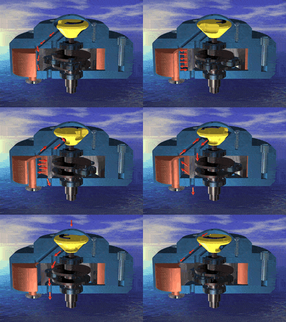
The motor concept is based on a rotary piston. Different from
existing rotary engines, Angelo's motor uses a simple
cylindrical rotary piston (shaft driver), which rolls, without
any friction, inside the cylindrical stator. The space between
stator and rotor is divided in six expansion chambers by
pivoting dividers. These dividers follow the motion of the shaft
driver as it rolls around the stator wall. The cylindrical shaft
driver, forced by the air pressure on its outer wall, moves
eccentrically, thereby driving the motor shaft by means of two
rolling elements mounted on bearings on the shaft. The rolling
motion of the shaft driver inside the stator is cushioned by a
thin air film. Timing and duration of the air inlet and exhaust
is governed by a slotted timer which is mounted on the output
shaft and rotates with the same speed as the motor.
Further information
Variation of performance parameters of the motor is easily
achieved by varying the time during which the air is allowed to
enter the chamber: A longer air inlet period allows more air to
flow into the chamber at high pressure and therefore results in
more torque. A shorter inlet period will limit the air supply
and allows the air in the chamber to perform expansion work at a
much higher efficiency. In this way compressed air (energy)
consumption can be exchanged for higher torque and power output
depending on the requirements of the application.
Motor speed and torque are simply controlled by throttling the
amount or pressure of air into the motor. Angelos motor gives
instant torque at zero RPM and can be precisely controlled to
give soft start and acceleration control.
---

**Angelo Di Pietro**
---
[**http://www.gizmag.com/go/3185/**](http://www.gizmag.com/go/3185/)
**Significant New Rotary Engine Design Runs on Compressed
Air**
*September 15, 2004* --- There is no other motor as
efficient as the Di Pietro Rotary Air Engine. It is 100% more
efficient than any other air powered engine built to date and
its high torque makes it the first air engine suitable for
mobile applications. The invention has the capacity to
revolutionise transportation, plus offer a multitude of
energy-saving benefits in stationary applications.
The engine has no emissions, is very quiet, has constant high
torque, a low parts count, no vibration and is very efficient -
only 1 PSI of pressure is needed to overcome the friction to
enable movement.
The engine has no emissions, is very quiet, has constant high
torque, a low parts count, no vibration and is very efficient -
only 1 PSI of pressure is needed to overcome the friction to
enable movement.
Former Mercedes Benz experimental engineer Angelo di Pietro
conceived the Rotary Air Engine while working in his
Melbourne-based Engineering business over many years.
"I started work on this project many years ago in my head,"
said Pietro, "and I have seen the need for such an engine many
times. As my engineering business was doing okay, I was able to
spend more time on the idea and with each new prototype the
design has been refined."
In 1999 he made a major design breakthrough and the first
prototype was constructed. Since then, six prototypes have been
built, each more efficient, more powerful and lighter than the
previous one.
It's not surprising that Di Pietro's design should be a rotary
engine. Angelo Di Pietro, (1950, Avellino, Italy) qualified as
Congegniatore Meccanico in Avellino moved to Stuttgart, Germany
to work on the Wankel rotary engine at the Mercedes Benz
research laboratories 1969 and 1970. In 1971 he migrated to
Australia where he established a construction engineering
company.
From his early experience with Wankel rotary engines, Angelo
became interested in developing a more efficient engine than the
traditional reciprocating internal combustion engine, and he has
worked on various alternative concepts intermittently over the
last 30 years.
Recognising the potential of his invention Di Pietro decided to
fully focus on the development of the new motor concept. The
principle worked with the first prototype and, although not
built to fine engineering tolerances, its performance far
exceeded expectations.
Engineair Pty Ltd (http://www.engineair.com.au/) was
established in September 2000, with the objective to perform
research and development on the innovative air motor design. In
the first 2 years the company focused on developing prototype
models to test the concept and understand the performance
characteristics. Current development status shows performance
and efficiency to be superior over state of the art air motor
technology.
Engineair is now entering the commercialisation of its
technology and is working on several fronts to prove the
engine's capability. One of the first commercial applications
will see the Engineair Rotary Air Engine applied in a commercial
and outdoor environment by Melbourne-based CityWide which has
replaced the petrol driven engine in one of its ParkCare garden
maintenance vehicles (known as a 'gator').
The vehicle will be used on the company's City of Melbourne
parks and garden maintenance contract. The project will run over
2004-05 enabling CityWide to test the vehicle under different
environmental conditions.
Engineair has already successfully tested the powerplant in a
roadgoing passenger car, a go-kart, a boat and as the power
source for a utility vehicle for use in the Melbourne Fruit and
Vegetable market, the latter project in conjunction with the
Melbourne Market Authority.
The Di Pietro motor concept is based on a rotary piston.
Different from existing rotary engines, the Di Pietro motor uses
a simple cylindrical rotary piston (shaft driver) which rolls,
without any friction, inside the cylindrical stator.
The space between stator and rotor is divided into six
expansion chambers by pivoting dividers. These dividers follow
the motion of the shaft driver as it rolls around the stator
wall.
The cylindrical shaft driver, forced by the air pressure on its
outer wall, moves eccentrically, thereby driving the motor shaft
by means of two rolling elements mounted on bearings on the
shaft.
The rolling motion of the shaft driver inside the stator is
cushioned by a thin air film. Timing and duration of the air
inlet and exhaust is governed by a slotted timer which is
mounted on the output shaft and rotates with the same speed as
the motor.
Variation of performance parameters of the motor is easily
achieved by varying the time during which the air is allowed to
enter the chamber: A longer air inlet period allows more air to
flow into the chamber at high pressure and therefore results in
more torque.
A shorter inlet period will limit the air supply and allows the
air in the chamber to perform expansion work at a much higher
efficiency. In this way compressed air (energy) consumption can
be exchanged for higher torque and power output depending on the
requirements of the application.
Motor speed and torque are simply controlled by throttling the
amount or pressure of air into the motor. The Di Pietro motor
gives instant torque at zero RPM and can be precisely controlled
to give soft start and acceleration control.
---
[**http://www.engineair.com.au/**](http://www.engineair.com.au/)
Engineair Pty Ltd, based in Melbourne, Australia is a company
focusing on the development of air motor technology based on a
unique rotary piston concept. Different from conventional air
motors, the Engineair motor, invented by Mr Angelo Di Pietro,
has virtually eliminated internal wear and friction and offers
superior performance at a wide variety of application
requirements.
We invite you to browse and familiarise yourself with the
innovative technology and it applications and opportunities
Engineair Pty Ltd
5 Export Drive
Brooklyn Vic 3012 Australia
Telephone 61 3 9318 0011
Facsimile 61 3 9318 0088
---
[**http://www.engineair.com.au/airmotor.htm**](http://www.engineair.com.au/airmotor.htm)
**The Di Pietro Motor (Rotary Air Engine)**
The Di Pietro motor concept is based on a rotary piston.
Different from existing rotary engines, the Di Pietro motor uses
a simple cylindrical rotary piston (shaft driver) which rolls,
without any friction, inside the cylindrical stator. The space
between stator and rotor is divided in 6 expansion chambers by
pivoting dividers. These dividers follow the motion of the shaft
driver as it rolls around the stator wall. The motor shown is
effectively a 6 cylinder expansion motor.
The cylindrical shaft driver, forced by the air pressure on its
outer wall, moves eccentrically, thereby driving the motor shaft
by means of two rolling elements (not shown) mounted on bearings
on the shaft. The rolling motion of the shaft driver inside the
stator is cushioned by a thin air film. Timing and duration of
the air inlet and exhaust is governed by a slotted timer which
is mounted on the output shaft and rotates with the same speed
as the motor.
Variation of performance parameters of the motor is easily
achieved by varying the time during which the air is allowed to
enter the chamber: A longer air inlet period allows more air to
flow into the chamber and therefore results in more torque. A
shorter inlet period will limit the air supply and allows the
air in the chamber to perform expansion work at a much higher
efficiency. In this way compressed air (energy) consumption can
be exchanged for higher torque and power output depending on the
requirements of the application.
Motor speed and torque are simply controlled by throttling the
amount or pressure of air into the motor. The Di Pietro motor
gives instant torque at zero RPM and can be precisely controlled
to give soft start and acceleration control.
Angelo Di Pietro Director of R & D said:
"There is no other motor as good as ours, years of research and
analysing other motors around the world gave me the confidence
and obligation to say so. Obligation in the sense that people
have been waiting for ages in relation to efficiency in order to
take care of our environmental situation.
100% more efficiency than our competitor is a very serious
claim and should not be confused with some kind of publicity
stunt were the interest is purely to try and make money out of
some ridiculous claim."
The invention has a long list of important improvements over
other motors.
The concept has the capability to change the method we use for
transportation, apart from the benefits of energy saving in
stationary applications.
We have verification of its performance
We have patents issued
It has outstanding efficiency
It has constant high torque
It has low parts count
It has low number of moving parts
It is compact and light
It has virtually no friction
It has virtually no vibration
It has smooth speed control characteristics
Only 1 PSI of pressure is needed to overcome the friction
---
**US Patent # 6,868,822**
**[ [PDF Format](us6868822.pdf)
]**
**Rotary Piston Engine**
**( 3-22-2005 )**
**Di Pietro, Angelo**
**Applicant:** ENGINEAIR PTY LTD (AU)
**Classification:** - international: F01C1/46; F01C1/00;
(IPC1-7): F02B53/04; F02B53/06; - european: F01C1/46
**Also published as:** WO0106093 // EP1204809 // CA2378960
**Abstract:** A non-reciprocating engine comprising a
hollow cylindrical shaft driver (13) located in a cylindrical
stator cavity (14) of a stator. A number of expansion chambers
(43) form between the outer wall of the shaft driver, the stator
wall and movable dividers (25) which extend from the stator to
bear on the shaft driver. The expansion chambers expand and
contract during operation of the engine. An output shaft passes
centrally through the stator cavity and shaft driver and has
offset bearings (34) which bear on the inside surface of the
shaft driver. Inlet ports in a removable inlet end plate of the
stator allow pressurised air or air/fuel mixture, for example,
to be introduced into the expansion chambers. Sequential
expansion and contraction of the chambers around the
circumference of the shaft driver causes a combination of
orbital and rotational movement of the shaft driver and
consequential rotation of the output shaft. The shaft driver
rotates at only a fraction of the speed of rotation of the
output shaft (in the order of {fraction
(1/10| -{fraction (1/20 | the speed of rotation
of the output shaft). One orbit of the shaft driver is
equivalent to one rotation of the output shaft.
***Description***
The present invention relates to motors or engines and more
particularly to a crankless engine which may be in the form of
an internal combustion engine, a fluid driven motor such as an
air motor, or a steam driven engine.
The term "crankless" refers to the fact that the motor does not
have a conventional crankshaft and is not subject to
reciprocating motion. The output shaft of the engine is in fact
a straight shaft which is caused to rotate by offset bearings
located in a drive member which may be termed a shaft driver,
although in the strict sense, the motion of the so-called shaft
driver is more an orbital motion with slow rotation relative to
the speed of rotation of the output shaft.
Many different forms of rotary and orbital engines as well as
other forms of engines have been proposed in the past with
varying degrees of success but overall there has been no serious
challenge to the reciprocating internal combustion engine at
least insofar as automobiles are concerned. This fact is
primarily due to the high wear rate in rotary engines and
possibly the fact that the improvements in efficiency of rotary
engines over reciprocating engines has not been sufficient to
justify a major change in direction for engine manufacturers.
It is an object of this invention to provide an alternative
form of a non-reciprocating type motor or engine which overcomes
one or more of the shortcomings of prior art engines.
Accordingly the invention provides an engine comprising a
hollow cylindrical shaft driver located in a stator cavity of
the engine and surrounded by expansion chambers defined between
the cylindrical wall of the shaft driver and the wall of the
stator cavity, said expansion chambers being separated by
movable dividers mounted in said stator and bearing on said
shaft driver, an output shaft rotatably supported in said stator
and passing centrally through said stator cavity and through
said shaft driver, said shaft having bearing means to one side
of said shaft which bear on the inside surface of said shaft
driver whereby a combination of orbital and rotational movement
of said shaft driver causes rotation of said shaft at a
rotational speed much greater than the rotational speed of said
shaft driver.
In order that the invention may be more readily understood one
particular embodiment will now be described with reference to
the accompanying drawings which show an air driven engine. In
the drawings:
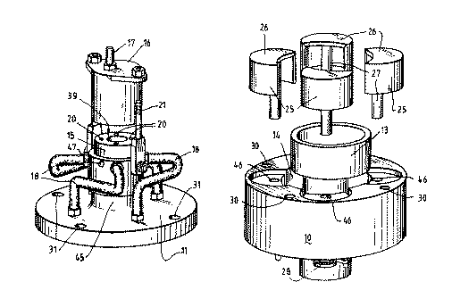
**[FIG. 1](fig1.jpg)** is a
perspective view from the inner side of an inlet end plate and
inlet manifold of the engine;
**[FIG. 2](fig2.jpg)** is a
perspective view, from the outside, of a stator of the engine
and shows, in exploded view, a shaft driver and movable dividers
of the engine;
**[FIG. 3](fig3.jpg)** is a
perspective view of an output shaft assembly of the engine;
**[FIG. 4](fig4.jpg)** is an end
view of the engine from the inlet manifold end;
**[FIG. 5](fig5.jpg)** is a view
similar to FIG. 4 with inlet end plate and output shaft removed;
**[FIG. 6](fig6.jpg)** is an end
view of the output shaft assembly;
**[FIG. 7](fig7.jpg)** is a
perspective view (partly exploded view) from the outer side of
the inlet end plate and inlet manifold;
**[FIG. 8](fig8.jpg)** is a
perspective view, from the inside, of the stator, shaft driver,
and movable dividers, in an exploded view;
**[FIG. 9](fig9.jpg)** is a
further perspective view (from the opposite end to FIG. 3) of
the output shaft assembly;
**[FIG. 10](fig10.jpg)** is
similar to FIG. 4 with end cap removed;
**[FIG. 11](fig11.jpg)** is an
end view of the engine from the output end with output shaft
removed;
**[FIG. 12](fig12.jpg)** is an
end view of the engine end plate with inlet manifold and end cap
removed;
**[FIG. 13](fig13.jpg)** is an
enlarged perspective view of a timing member located at the
inner end of the output shaft; and
**[FIGS. 14(i)-(iv)](fig14.jpg)**
show a cycle of the shaft driver within the stator cavity to
produce a single revolution of the output shaft.
In the drawings, the engine is shown to comprise essentially a
stator 10, an inlet end plate 11 and a output shaft 12. A shaft
driver 13 is a hollow cylindrical ring which, when the engine is
assembled, is located in a cylindrical stator cavity 14 of the
stator 10.
The inlet end plate 11 has an inlet manifold 15 mounted
centrally on the outer end thereof and a removable end cap 16
provides an air intake 17 to the inlet manifold 15. The inlet
manifold 15 (see FIG. 7) fits over a cylindrical boss 45 of the
end plate 11 and is locked onto the boss 45 by grub screws (not
shown). The rotational position of the manifold 15 relative to
the boss 45 may be adjusted to vary the timing of the engine. As
is evident flexible pressure hoses 18 extend from the inlet
manifold to inlet ports 19 in the end plate 11. The interior of
the end cap 16 communicates with ports 20 (see FIG. 7), each of
which communicates with one of the pressure hoses 18 to
distribute inlet air at air intake 17 to the respective inlet
ports 19 via the pressure hoses 18. The ports 20 are opened or
closed by a timing member 36 locked to the inner end of output
shaft 12 as will be described hereinafter. The end cap 16 is
fixed to the inlet manifold 15 by bolts 21 which extend axially
and enable the end cap 16 to be clamped firmly to the inlet
manifold 15 in an airtight arrangement. A roller bearing 22 is
located in the end plate 11 to support the output shaft 12.
As is more evidence in FIGS. 5 and 8, the stator 10 has a
cylindrical stator 14 which is larger in diameter than the
diameter of the shaft driver 13. The wall 23 of the stator 10
has part cylindrical grooves 24 which extend arcuately from a
point in the stator cavity through the wall 23 and back to the
stator cavity at a circumferentially displaced location. These
grooves 24 accommodate respective movable dividers 25 which are
able to move in the respective grooves 24 whereby an edge of a
moveable divider 25 bears on the outer surface of the shaft
driver 13. As is evident in FIG. 8 for example, the movable
dividers 25 are part cylindrical dividers with a end portion 26
which supports an axial shaft 27 on which the divider pivots.
The axial shaft 27 extends through a hole 46 in the stator 10
and passes out the end of the stator. As can be seen more
clearly in FIG. 11, a spiral spring 28 locates in a slot in the
end of each axial shaft 27 and is fixed to the stator 10 in
order to bias pivotal movement of the respective moveable
divider in a manner whereby an edge of the divider bears on the
shaft driver 13. A further roller bearing 29 is located in the
stator to support the output shaft 12. As is apparent in the
drawings, holes 30 in the stator 10 and corresponding holes 31
in the end plate 11 enable the two parts to be bolted together
in sealing engagement by bolts (not shown).
As is evident in FIGS. 5 and 11, exhaust ports 32 extend from
the cylindrical stator cavity 14 through the fixed end of the
stator 10 to allow exhaust air to dissipate to atmosphere. In
addition to these exhaust ports 32, which allow primary exhaust
air to dissipate at the opposite end of the stator 10 to the
inlet manifold 15, a further or secondary exhaust route is
provided via the inlet ports 19 and the inlet manifold 15. The
secondary exhaust route follows the inlet air path back to the
start of the ports 20 and a timing member or disc member 36.
(FIG. 13) which bears on the outer surface 39 (FIG. 10) of the
inlet manifold 15. A recessed portion 37 of the timing or disc
member 36 allows one of the ports 20 to communicate with the
bore of the timing disc 36. The bore of the timing or disc
member 36 is a clearance fit over output shaft 12 (creating
space 40) and thus any exhaust air forced back via the inlet
manifold to timing or disc member 36 is captured within the
recessed portion 37 and forced into space 40. As radial hole 47
in the inlet manifold extend to the space 40 and provides an
exhaust outlet for this secondary exhaust air.
The output shaft 12 consists essentially of a straight shaft
that is mounted in the roller bearings 22 and 29 of the inlet
end plate 11 and stator 10, respectively. A driven plate 33 is
mounted on the shaft and in the assembled engine locates within
the shaft driver 13. The driven plate 33 has mounted thereon a
pair of roller bearings 34 which are closely adjacent to each
other and to one side of the shaft. The roller bearings 34 bear
on the inside wall of the shaft driver 13 and are driven around
the inner perimeter of the shaft driver 13 as will become
apparent hereinbelow. The driven plate 33 is arranged to be
rotationally balanced with the roller bearings 34. At the inner
end of the shaft 12 a nut 35 retains the timing disc 36 on the
shaft. The timing or disc member 36 has recessed portion 37 in a
surface 38 of the timing or disc member 36 which bears on the
outer surface 39 of the inlet manifold 15. As is evident in FIG.
10, the manifold 15 fits over the output shaft 12 and a space 40
exists therebetween. The recessed portion 37 as it moves around
on the outer surface 39 exposes the ports 20 to the space
between the inlet manifold and the shaft. The previously
described radial hole 47 in the inlet manifold communicates with
the space 40 and enables further exhausting of air in an
expansion chamber of the engine as will become apparent
hereinbelow.
A cut-out portion 42 in the circumference of the timing or disc
member 36 exposes the ports 20 to inlet air pressure from the
air intake 17. The timing or disc member 36 is therefore
responsible for timing functions related to inlet air pressure
and secondary exhaust air from the expansion chambers.
As will be evident in FIG. 5 and FIG. 14, expansion chambers 43
of the engine are formed between the outer surface of the shaft
driver 13, the surface of the stator cavity 14 and between the
dividers 25 where they contact the surface of the shaft driver
13. These expansion chambers 43 take varying shapes as the shaft
driver 13 moves within the stator cavity 14. In order to better
understand this movement, reference should now be made to FIG.
14 which shows a cycle of the engine resulting in a complete
revolution of the output shaft 12. The engine is driven in this
embodiment by compressed air and air under pressure is therefore
connected to air intake 17 on the end cap 16. A suitable valve
(not shown) is provided in order to open the supply of
compressed air.
In FIG. 14, the four expansion chambers are labelled (a), (b),
(c) and (d) for convenience in explaining a cycle of operation.
Referring to FIG. 14(i), the expansion chamber 43(a) is
receiving pressurised air because the timing member 36 is
positioned on the end of the inlet manifold so as to expose the
relevant port 20 to the pressurised air. Pressure in expansion
chamber 43(a) creates a force against the side of the shaft
driver 13 causing it to move in a direction whereby its contact
with the surface of stator cavity 14 moves in an anti-clockwise
direction. In other words, the shaft driver 13 does not
specifically rotate but moves in a type of motion whereby the
point or surface contact between it and the stator cavity 14
moves around the circumference of the stator cavity 14. Further
expansion of the chamber 43(a) causes the shaft driver 13 to
assume a position as shown in FIG. 14(ii) and at this point in
time, the shaft has rotated through 90.degree. as shown by the
position of the roller bearings 34 which are forced to remain in
a space available internally in the shaft driver 13 by virtue of
its offset position relative to the axes of the output shaft 12.
This rotation of the output shaft 12 through 90.degree. causes
the timing member 36 to expose the next relevant port 20 to high
pressure air which then enters the expansion chamber 43(b)
further pushing the shaft driver 13 around within the stator
cavity 14.
It should be mentioned at this time that whilst the movable
dividers are spring biased so that an edge thereof remains in
contact with the outer surface of the shaft driver 13, pressure
in an expansion chamber also acts via arcuate grooves 24 on the
edge of the divider 25 not in contact with the shaft driver 13,
to thereby assist in applying pressure between the divider and
shaft driver.
Referring now to FIG. 14(iii), it can be seen that the cycle
continues and in the position shown in FIG. 14(iii), the shaft
has rotated 180.degree.. In this position, compressed air is
being received in expansion chamber 43(c) whilst chambers 43(a)
and 43(b) have been fully expanded. It should be noted that
movement of the shaft driver 13 has exposed exhaust port 32 in
chamber 43(a) whereby subsequent contraction of the chamber
43(a) by further movement of the shaft driver allows some of the
air in chamber 43(a) to exhaust via the exhaust port 32.
As shown in FIG. 14(iv), the shaft driver 13 has moved to a new
position whereby the output shaft 12 has rotated through
270.degree. from the initial position. In this position, the
exhaust port 32 shown in FIG. 14(iii) has been closed by the
movement of the shaft driver 13 but the chamber 43(a) is still
contracting. This contraction of chamber 43(a) would compress
air in that chamber if there was no other means for the air to
escape. Such means is provided by the previously described
secondary exhaust route. This enables air to return via the
appropriate inlet port 20, into the recessed portion 37 of the
timing member 36 and then into the space 40 between the inlet
manifold and output shaft to eventually exit via exhaust port or
radial hole 47. This means that the expansion chamber 43(a) can
continue to contract in size as is evident in FIGS. 14(iii) and
14(iv) without compressing air in that chamber and resisting
such movement. Similar events occur as the other chambers
contract. In the next step of the cycle the components resume
the position shown in FIG. 14(i).
As will be evident from the above description, the shaft driver
13 moves in the stator cavity 14 whereby contact between the
outer circumference of the shaft driver 13 and the surface of
stator cavity 14 moves around the cavity 14 as each expansion
chamber receives compressed air. This movement may be considered
as a type of orbital movement and whilst the shaft driver 13
does not rotate at the same speed as the output shaft 12, there
is some rotation of the shaft driver 13. The speed of rotation
of the shaft driver 13 depends upon the difference in
circumference between the shaft driver and the stator cavity 14.
Generally speaking, the shaft driver 13 rotates at a speed of
about 1/12.sup.th to 1/20.sup.th of the speed of rotation of the
output shaft 12. This provides a distinct advantage in that
there is minimal wear between the surface of the movable
dividers 25 where they contact the shaft driver 13 and the
surface of the shaft driver 13. This is because there is little
rotation of the shaft driver 13 relative to the output shaft 12.
As will also be evident, rotation of the output shaft 12 is
caused by the roller bearings 34 moving, or remaining, in the
space provided for them within the shaft driver 13.
The direction of rotation of the output shaft 12 is simply
reversed by rotating the manifold 15 on the cylindrical boss 45.
The rotation of the manifold will expose next port 20 to the
cut-out portion 42 in the circumference of the timing member 36
to communicate the interior of the end cap 16 with chamber 43(b)
instead of chamber 43(a) as per FIG. 14(i).
Whilst the embodiment described above relates to an engine
driven by compressed air, clearly other types of engines may be
readily constructed. For example, by providing spark plugs in
the stator cavity 14 for each expansion chamber and introducing
a fuel/air mixture into the engine, an internal combustion
engine may be provided. Also, the engine could be driven by
steam or by other fluid means. It is also conceivable that an
internal combustion engine embodiment of the invention could
drive a vehicle as well as an air compressor in the vehicle
whereby during certain times, the fuel air mixture could be
turned off and the engine could run from compressed air provided
by the compressor. This would have advantages where fuel is not
available or where pollution by internal combustion engine
exhaust is a sensitive issue. For example, within certain city
limits internal combustion engines may be prevented from use in
the future and an engine of the type described herein could be
run on compressed air for periods of time whilst in these areas.
It should be apparent that the engine according to the present
invention offers many advantages over existing engines. For
example, the engine is non-reciprocating and therefore is
essentially vibration free. There are fewer moving parts and
minimum friction resulting in a much more efficient engine with
minimum wear. The output shaft of the engine is a straight shaft
and therefore avoids many of the inherent balancing and
vibration problems of existing reciprocating engines. In order
to increase the output power of the engine according to this
invention, it is merely necessary to provide additional stator
assemblies on the same output shaft. The engine is compact and
lighter than existing engines and this results in improved
efficiency.
Whilst one particular embodiment has been described in detail,
it should be evident to persons skilled in the art that
variations may be readily effected without departing from the
spirit and scope of the invention. Clearly additional parts can
be added to provide a production version of the engine. For
example, it would be necessary to provide an outlet manifold
covering the exhaust ports 32 in order to direct the exhaust air
to a single exhaust outlet point. Also, a fly-wheel (not shown)
would be provided in order to contribute to the smoother running
of the engine.
--- |